IOP-620 - YARD RAMP
Looking for a specific replacement part? Ctrl-F (or Command-F for Mac users) brings up your browsers search panel and can search any text on the entire web page. Find parts by searching a part # or part description.
Register your equipment with BHS Optima, BHS's free app.
California Residents: WARNING: This product contains chemicals known to the State of California to cause cancer and/or reproductive harm, and birth defects or other reproductive harm. Learn more here.
Yard Ramp (YR) System Parts & Service Manual
TP-635 - SAFETY AND DE-ENERGIZATION PROCEDURES
GENERAL SAFETY
- Read and understand all instructions and warnings before using or servicing this equipment.
- Keep these instructions for future reference.
- Yard Ramps shall only be operated by suitable persons of at least 18 years of age, who have been trained in the proper and safe operation of the Yard Ramp and expressly certified/charged, in writing, by the user or their representative.
- Yard Ramps shall only be used on level, dry, solid surfaces suitable for maneuvering large industrial trucks.
WORK AREA
- Keep ramp surfaces clear and free of debris. Cluttered and or obstructed work surfaces can lead to accidents.
- Clean up/contain any fluid spills immediately to prevent slips or falls.
- Be aware of potential hazards when performing any service or maintenance to the unit.
SERVICE & MAINTENANCE
Service personnel shall wear Personal Protective Equipment (PPE) appropriate for the task being performed.
LOCKOUT/TAGOUT
Lockout/tagout the BWC per your corporate policy, if damaged or not functioning properly. Lockout/tagout and de-energize all systems prior to performing any maintenance or service to unit.
HYDRAULIC HAZARDS
AVOID HIGH PRESSURE FLUIDS-Escaping fluid under pressure can penetrate the skin causing serious injury. Relieve pressure before disconnecting hydraulic lines. Tighten all connections before applying pressure. Keep hands and body away from pin holes which eject fluids under high pressure. Use a piece of cardboard or paper to search for leaks. DO NOT use your hand.
Any fluid injected into the skin under high pressure should be considered a serious medical emergency despite an initial normal appearance of the skin. There will be a delayed onset of pain, and serious tissue damage may occur. Medical attention should be sought immediately.
OPERATIONAL SAFETY
OPERATIONAL SAFETY
- Only personnel trained in the proper and safe operation of Yard Ramps may operate or service the ramp.
- All data plates, warning labels, placards, etc. shall be in place and legible at all times. Contact BHS for replacement data plates, warning labels, placards or instructions.
- All users and service personnel shall be familiar with the meaning and risks associated with all data plates, warning labels, etc.
- All operators and service personnel shall be aware of potential crush and shear points while operating or servicing the Yard Ramp.
- Keep keep arms, hands, legs and feet clear of approach and landing plates when raising and lowering the Yard Ramp.
- Remove Yard Ramp from service if damaged, defective, or operating improperly (or becomes such while operating) until repairs can be made to correct any problem(s).
- Ensure securing chains are attached to the vehicle or platform prior to ascending or descending ramp.
- Ensure vehicle wheels have been chocked prior to traversing ramp.
- Remove the hand pump handle after Yard Ramp has been positioned for use and securing chains have been attached.
SAFETY DO’s AND DON’T’s
- DO NOT exceed the maximum capacity of the Yard Ramp.
- DO NOT lift raise or lower the Yard Ramp while loaded.
- DO NOT modify or fit the Yard Ramp with attachments without prior, written approval from BHS.
- DO NOT perform any maintenance or service to the Yard Ramp with a load on the ramp.
- DO NOT allow anyone to ride on the Yard Ramp while being moved or towed.
- DO NOT allow anyone to enter the area under the Yard Ramp while in use.
- DO NOT use the Yard Ramp in a manner for which it is not intended. Some examples of prohibited use are but not limited to:
- To transport people
- As a vehicle jack
- To support loads greater than its rated load capacity
- Where unintentional movement may exist
- DO NOT traverse the Yard Ramp with hand pump relief valve in the closed position.
- DO NOT traverse the Yard Ramp with the hand pump handle installed on the pump.
- DO NOT transport the Yard Ramp over the road.
- DO NOT exceed 5 mph while transporting the Yard Ramp.
- DO NOT transport the Yard Ramp with the relief valve closed.
DE-ENERGIZATION
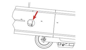
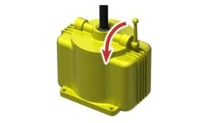
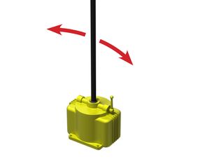
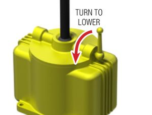
- Fully lower the ramp onto the landing gear by slowly turning the relief valve handle, located on the left side of the ramp, counter-clockwise. See Figures 1 & 2.
Failure to properly support the Yard Ramp when performing service under the ramp could result in injury from the roller bed lowering unexpectedly.
'Failure to release any stored hydraulic pressure could result in injury from: *Escaping hydraulic fluid under high pressure (see HYDRAULIC HAZARDS in the GENERAL SAFETY section). *Unexpected movement of hydraulic components.
FIGURE 1
FIGURE 2
GENERAL INFORMATION
The Yard Ramp (YR) is used for loading and unloading trucks when a dock is not present or accessible. The Yard ramp can be transported to a loading/off loading site by way of the included fork clamp or by using the optional tow bar.
The Yard Ramp rides on a set of 16" diameter, solid rubber wheels and is raised and lowered using a manual, hydraulic hand pump for height positioning on the vehicle or platform being accessed. A set of securing chains attach to the vehicle or platform to prevent the ramp from disengaging during use.
Refer to hand pump manual for specifics on operation, maintenance, troubleshooting and replacement parts.
SPECIFICATION DATA
Model | Overall Width | Overall Length | Usable Width | Capacity |
YR-8436-16 | 84” / 2134 mm | 36’ / 10.973 m | 78” / 1981 mm | 16,000 lb / 7258 kg |
YR-8436-20 | 84” / 2134 mm | 36’ / 10.973 m | 78” / 1981 mm | 20,000 lb / 9072 kg |
YR-8436-25 | 84” / 2134 mm | 36’ / 10.973 m | 78” / 1981 mm | 25,000 lb / 11340 kg |
OPERATING CONTROLS
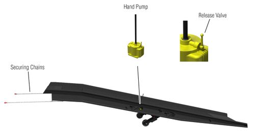
Hand Pump – Used to raise Yard Ramp to vehicle or platform height.
Release valve – Used to lower the Yard Ramp onto vehicle or platform after positioning or in preparation for transport.
SAFETY FEATURES
Securing Chains - For securing the Yard Ramp to the vehicle or platform being loaded/unloaded to prevent the ramp from dislodging during use.
OPERATING INSTRUCTIONS
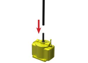
Raising 1. Slip the hand pump handle onto the shaft of the hand pump. See Figure 1
FIGURE 1
2. Move the handle forwards and backwards to raise the ramp. See Figure 2.
![]()
DO NOT continue to cycle the pump handle once maximum ramp height is reached. Damage to hydraulic components may occur.
FIGURE 2
Lowering
1. Slowly turn the release valve handle counter-clockwise to lower the ramp. Turn the handle back clockwise to stop lowering. See Figure 3.
FIGURE 3
Maneuvering (with Fork Clamp)
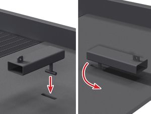
- Orient the fork clamp 90 degrees to the ramp. Insert the T-pin of the fork clamp into the slot in the approach plate and turn the fork clamp so that the clamp is aligned with the ramp. See Figure 4
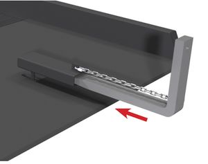
- Fully insert a lifting fork into the fork clamp opening. See Figure 5.
- Secure the fork clamp to the fork by looping the fork clamp chain around the fork to prevent the clamp from sliding off the end of the fork.
- Slowly raise the ramp off the ground just high enough so that the ramp approach plate does not contact the ground during transport.
- Maneuver the ramp to the location where it is to be used.
FIGURE 4
FIGURE 5
Ensure the ramp is in the fully lowered position and the release valve is open prior to transporting. DO NOT exceed 5 mph when transporting the ramp.
Positioning
- Position the ramp in-line with the vehicle or platform to be accessed. Move the ramp approximately 1' away from the vehicle or platform.
- Raise the ramp so the top lip of the ramp is above the vehicle/platform.
- Slowly move the ramp towards the vehicle/platform until contact is made.
- Slowly lower the ramp until the top landing lip is fully resting on the vehicle/platform. Do not close the release valve after lowering.
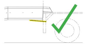
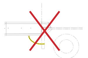
- Secure the ramp to the vehicle using the securing chains on the top of the ramp. Attach the chains to sturdy part of the vehicle or platform structure. Ensure the chains are as taught and horizontal as possible, allowing for variation in vehicle height due to shifting loads/suspension changes. See Figures 6 & 7
Failure to leave release valve open when traversing ramp could cause damage to hydraulic components due to shifting loads and/or movement of vehicle suspension.
FIGURE 6
FIGURE 7
Storage
1. If Yard Ramp is to be idle or in storage for an extended period of time, it is recommended to support the upper lip of the ramp with a stable structure and open the release valve. This will release the hydraulic pressure on the system, remove the weight from and prevent flat spots from developing on the tires.
PARTS SECTIONS
CHASSIS
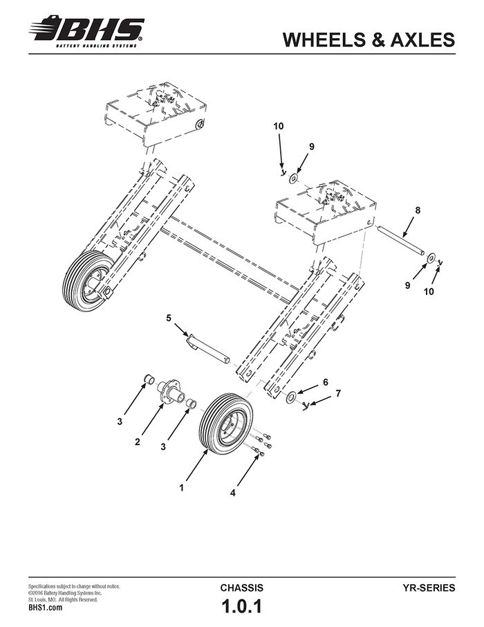
WHEELS & AXLES
ITEM | BHS PART NUMBER | DESCRIPTION | REF. KIT NO. | NOTES | NO. REQ |
1 | C0650 | WHEEL-16" X 4"-SOLID | 2 | ||
2 | 62225001 | WHEEL HUB | 2 | ||
3 | PT0480 | BEARING-BRONZE-1 1/2" ID X 1 3/4" OD | 4 | ||
4 | HW0526 | LUG BOLT-1/2-20 X 1" | 10 | ||
5 | 62225002 | SHAFT-WHEEL | 2 | ||
6 | HW0155 | WASHER-FLAT-1 1/2"-SAE | 2 | ||
7 | HW1152 | COTTER PIN-1/4" X 2 1/2" | 2 | ||
8 | 62217024 | PIN-PIVOT | 2 | ||
9 | HW0119 | WASHER-FLAT-1"-SAE | 4 | ||
10 | HW1153 | COTTER PIN-3/16" X 1 3/4" | 4 |
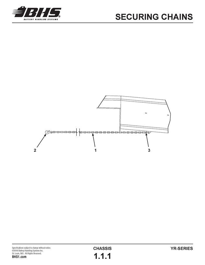
SECURING CHAINS
ITEM | BHS PART NUMBER | DESCRIPTION | REF. KIT NO. | NOTES | NO. REQ |
- | 62292001 | SECURING CHAIN ASSEMBLY | INCLUDES ITEMS 1 -3 | 2 | |
1 | 62298001 | CHAIN-5/16"-GR 30 | APPROX. 8' EA | 2 | |
2 | HW1151 | GRAB HOOK-5/16" | 2 | ||
3 | HW1150 | QUICK LINK-3/8" | 2 |
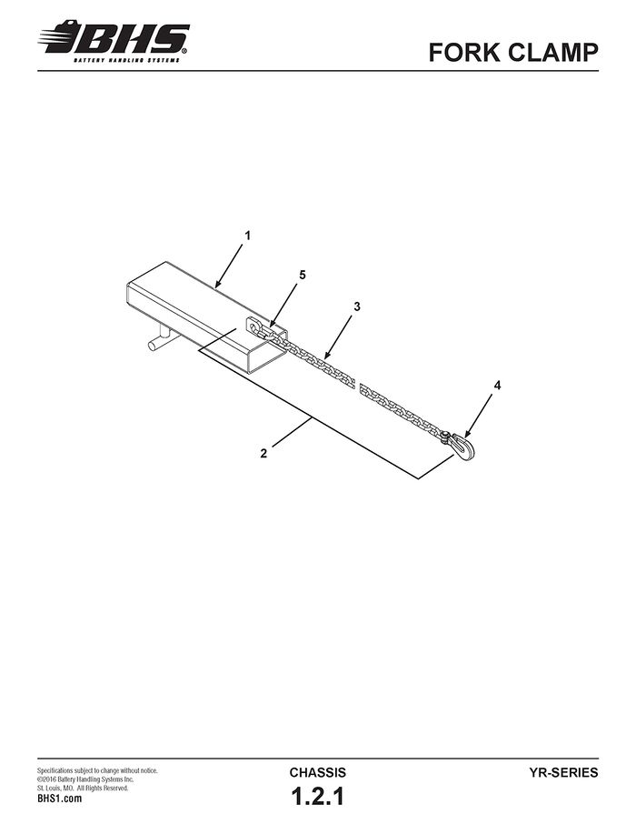
FORK CLAMP
ITEM | BHS PART NUMBER | DESCRIPTION | REF. KIT NO. | NOTES | NO. REQ |
1 | 62015001 | FORK CLAMP | 1 | ||
2 | 62092001 | CHAIN ASSEMBLY | INCLUDES ITEMS 3-5 | 1 | |
3 | 62098001 | CHAIN-5/16"-GR 30 | APPROX. 6' LG | 1 | |
4 | HW1151 | GRAB HOOK-5/16" | 1 | ||
5 | HW1150 | QUICK LINK-3/8" | 1 |
HYDRAULICS
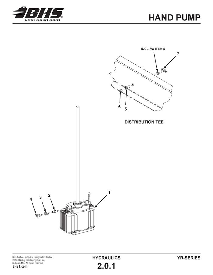
HAND PUMP
ITEM | BHS PART NUMBER | DESCRIPTION | REF. KIT NO. | NOTES | NO. REQ |
1 | HC0471 | HAND PUMP | † INCLUDES HANDLE | 1 | |
2 | H0001 | NIPPLE-CLOSE-1/4 NPT | 1 | ||
3 | H0100 | COUPLING-1/4 NPT | 1 | ||
4 | H1579 | ADAPTER-90 DEG-#6 JICM X #4 NPT | 1 | ||
5 | H0010 | FITTING-BULKHEAD-1/4" NPT | 1 | ||
6 | H1504 | ADAPTER-90 DEG-#6 JICM X #4 NPT | 1 | ||
7 | H1620 | TEE-BRANCH-#6 JICM X #4 NPT | 1 |
† REFER TO SUPPLIED HAND PUMP MANUAL AND / OR CONSULT PUMP MANUFACTURE FOR PARTS AND SERVICE INFORMATION.
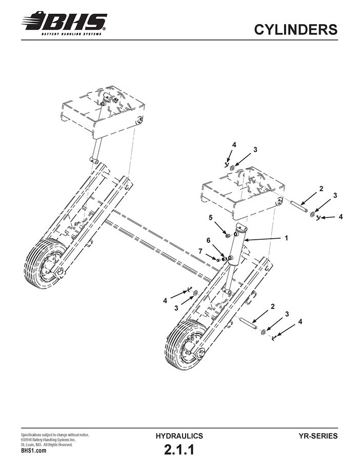
CYLINDERS
ITEM | BHS PART NUMBER | DESCRIPTION | REF. KIT NO. | NOTES | NO. REQ |
1 | HC0470 | CYLINDER-2 1/2" X 6" | 2 | ||
2 | 62217025 | PIN-CYLINDER | 2 | ||
3 | HW0116 | WASHER-FLAT-3/4"-SAE | 8 | ||
4 | HW1153 | COTTER PIN-3/16" X 1 3/4" | 8 | ||
5 | H1546 | ADAPTER-#6 JICM X #8 SAEM | 2 | ||
6 | H1001 | ADAPTER-#8 SAEM X #6 FNPT | 2 | ||
7 | P0218 | FILTER/BREATHER | 2 | ||
8 | 62042001 | HOSE KIT | NOT SHOWN | 1 |
STATEMENT OF WARRANTY
Statement of Warranty
Click here for details on BHS' Statement of Warranty
