IOP-402 BE-QS
Looking for a specific replacement part? Ctrl-F (or Command-F for Mac users) brings up your browsers search panel and can search any text on the entire web page. Find parts by searching a part# or part description.
Register your equipment with BHS Optima, BHS's free app.
California Residents: WARNING: This product contains chemicals known to the State of California to cause cancer and/or reproductive harm, and birth defects or other reproductive harm. Learn more here.
Quad Stack Operator Aboard Battery Extractors (BE-QS) Parts & Service Manual
TP-606 - SAFETY AND DE-ENERGIZATION PROCEDURES
GENERAL INFORMATION
GENERAL SAFETY
- Read and understand all instructions and warnings before using or servicing this equipment.
- Keep these instructions for future reference.
- Battery Extractor (BE) units shall only be operated by suitable persons of at least 18 years of age, who have been trained in the proper and safe operation of the BE and expressly certified/charged, in writing, by the user or their representative.
- Only one person is permitted to travel on the BE at any time.
- BE units shall only be used indoors in an industrial setting on a hard, nonslip, and level floor without defects including but not limited to holes, gouges, cracks, drains or obstacles comprised of concrete or other suitable industrial material meeting the minimum requirements specified by BHS as well as any local requirements.
- A licensed structural engineer should be consulted prior to installing a BE on any building level other than the ground floor.
- BE units are not designed to be shipped or transported after initial delivery.
WORK AREA
- Keep work area clean and well lit. Cluttered work areas and poor lighting can lead to accidents.
- Clean up/contain any fluid spills immediately to prevent slips or falls.
- Be aware of potential hazards when performing any service or maintenance to the unit.
SERVICE & MAINTENANCE
Service personnel shall wear Personal Protective Equipment (PPE) appropriate for the task being performed.
LOCKOUT/TAGOUT
Lockout/tagout the BE per your corporate policy, if damaged or not functioning properly. Lockout/tagout and de-energize all systems prior to performing any maintenance or service to unit.
LEAD-ACID BATTERIES-EXPLOSION HAZARD
Do not allow open flames or sparks of any kind near a battery. Highly explosive gas is generated when charging a battery that can remain in battery cells for extended periods of time after charging is complete.
- Always wear appropriate PPE including rubber apron, gloves, boots and full face shield when performing service or maintenance to any lead-acid batteries.
- Do not place metal or other conductive objects on top of battery. Arcing may occur causing damage to the battery and/or serious personal injury or death.
- Use only chargers matching the voltage and amperage of the battery being charged. Overcharging a battery can cause damage to the battery, charger and/or serious personal injury or death.
- Turn off charger before disconnecting battery from charger. Arcing between battery and charger connectors can cause damage to the connectors and/or serious personal injury or death.
HYDRAULIC HAZARD
AVOID HIGH PRESSURE FLUIDS-Escaping fluid under pressure can penetrate the skin causing serious injury. Relieve pressure before disconnecting hydraulic lines. Tighten all connections before applying pressure. Keep hands and body away from pin holes which eject fluids under high pressure. Use a piece of cardboard or paper to search for leaks. DO NOT use your hand.
Any fluid injected into the skin under high pressure should be considered a serious medical emergency despite an initial normal appearance of the skin. There will be a delayed onset of pain, and serious tissue damage may occur. Medical attention should be sought immediately.
OPERATIONAL SAFETY
OPERATIONAL SAFETY
- Only personnel trained in the proper and safe operation of BE units may operate or service the BE
- Operators shall wear appropriate PPE suitable for working with industrial lead-acid batteries while operating the BE (see prior page).
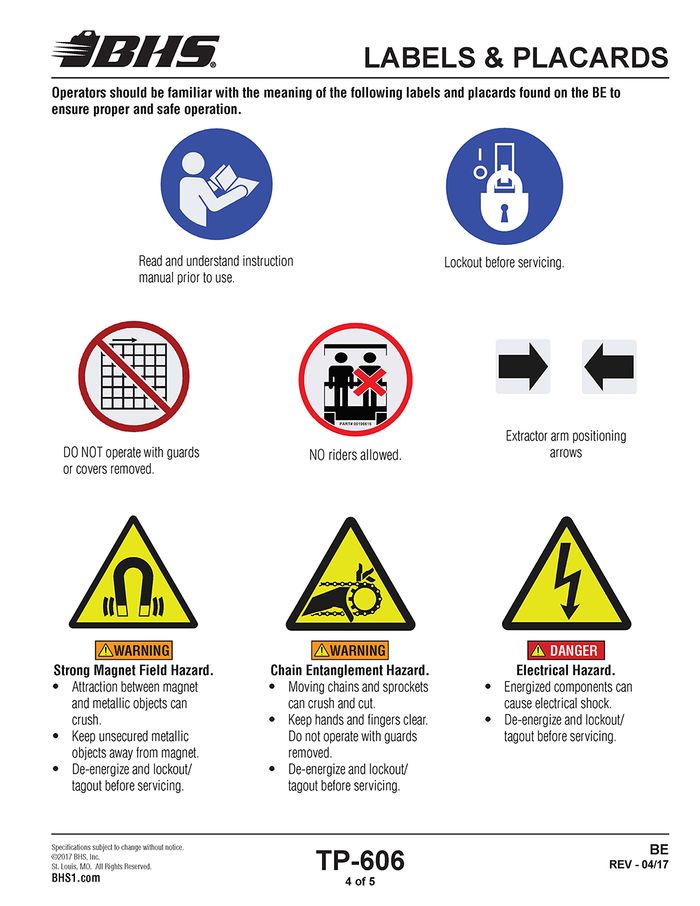
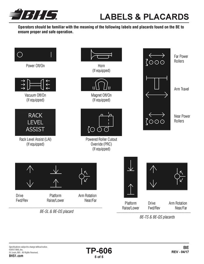
- All data plates, warning labels, placards, etc shall be in place and legible at all times. Contact BHS for replacement data plates, warning labels, placards or instructions.
- All users and service personnel shall be familiar with the meaning and risks associated with all data plates, warning labels, etc.
- All operators and service personnel shall be aware of potential crush and shear points while operating or servicing the BE.
- Keep hands and arms out of the battery compartment while operating the BE.
- Remove BE from service if damaged, defective, or operating improperly (or becomes such while operating) until repairs can be made to correct any problem(s).
- All operators shall be aware of the location of the end stops in the travel path to prevent driving the BE into the end stops.
- Persons with pacemakers (or similar type medical devices) should not operate, or be in close proximity to during operation, any BHS equipment utilizing magnetic extraction.
DO’s AND DON’T’s
- DO NOT exceed the maximum capacity of the BE.
- DO NOT modify or fit the BE with attachments without prior, written approval from BHS.
- DO NOT perform any maintenance or service to the BE with a battery loaded on the BE.
- DO NOT allow anyone to ride in or on the BE.
- DO NOT operate the BE with any guard or cover removed unless required for maintenance or repair.
- Disconnect the BE from all power sources before attempting to perform service or maintenance to the unit.
- DO NOT drive the BE into the end stops.
- DO NOT operate the BE if disengaged from the guidance track.
- DO NOT allow a battery to exit the BE when a lift truck or battery stand is not present to accept the battery.
- DO NOT use the BE in a manner for which it is not intended. Some examples of prohibited use are but not limited to:
- To transport people
- As a vehicle jack
- To lift loads greater than its rated load capacity
- Where unintentional movement may exist
- Having direct contact with foodstuff
- In a potentially explosive atmosphere
DE-ENERGIZATION
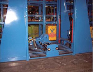
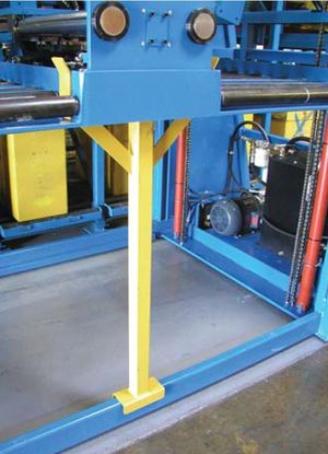
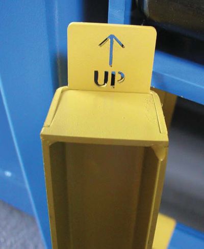
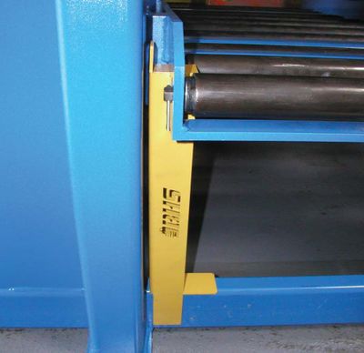
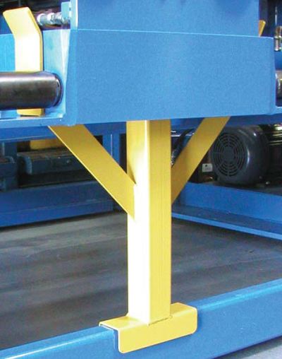
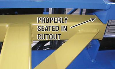
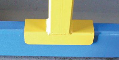
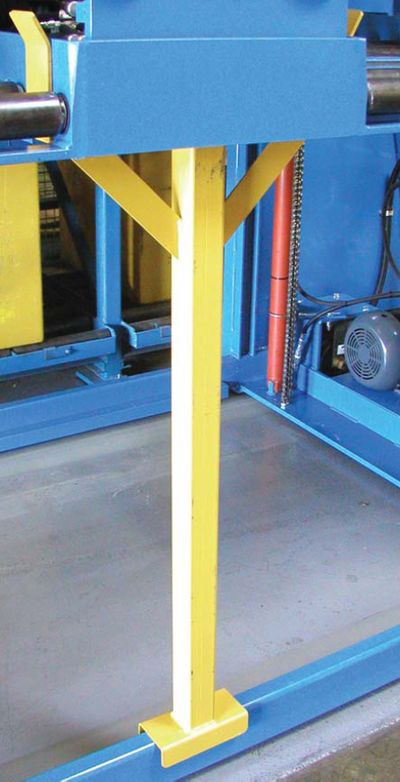
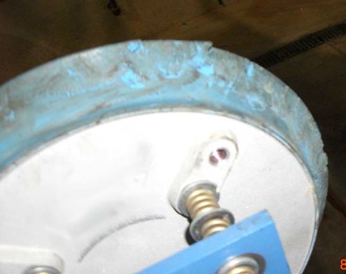
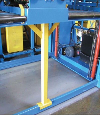
- Fully lower the BE roller bed or position the roller bed on service stands if service requires the bed be raised. See Figures 1 & 2.
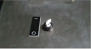
- Turn key on dashboard to the “OFF” position. See Figure 3.
- Disconnect power to the extractor or shut off the electrical branch circuit breaker.
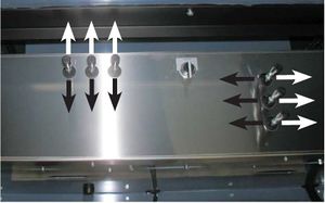
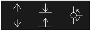
- Actuate all hydraulic levers in both directions to release any stored hydraulic pressure. See Figure 4.
FIGURE 1
FIGURE 2
FIGURE 3
LABELS & PLACARDS
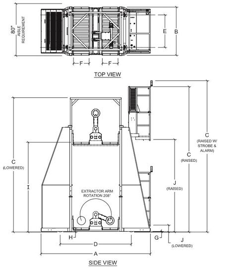
SPECIFICATION DATA
BE-24-2-QS | BE-36-2-QS | BE-42-2-QS | ||
A | Overall Length | 168" | 192" | 204" |
B | Overall Width | 74" | 74" | 74" |
C | Overall Height (Lowered) | 206" | 206" | 206" |
Overall Height (Raised) | 223" | 223" | 223" | |
Overall Height (Raised w/ Strobe & Alarm) | 232" | 232" | 232" | |
D | Wheel Base | 109" | 133" | 145" |
E | Drive Wheel Center Line | 51" | 51" | 51" |
F | Battery Compartment Width | 24" | 36" | 42" |
G | Ground Clearance | .625" | .625" | .625" |
H | Minimum Roller Height | 6.5" | 6.5" | 6.5" |
I | Maximum Roller Height | 136.75" | 136.75" | 136.75" |
J | Operator Platform Height (Lowered/Raised) | 11" / 145" | 11" / 145" | 11" / 145" |
QUAD STACK
SPECIFICATIONS (IMPERIAL / METRIC)
BE-24-2-QS | BE-36-2-QS | BE-42-2-QS | |
Travel Speed | 0 to 240 ft/min / 0 to 1.22 m/s | 0 to 240 ft/min / 0 to 1.22 m/s | 0 to 240 ft/min / 0 to 1.22 m/s |
Raise - Lower Speed | 0 to 26 ft/min / 0 to 0.13 m/s | 0 to 26 ft/min / 0 to 0.13 m/s | 0 to 26 ft/min / 0 to 0.13 m/s |
Powered Roller Speed | 0 to 37 ft/min / 0 to 0.19 m/s | 0 to 37 ft/min / 0 to 0.19 m/s | 0 to 37 ft/min / 0 to 0.19 m/s |
Arm Traverse Speed | 0 to 24 ft/min / 0 to 0.12 m/s | 0 to 24 ft/min / 0 to 0.12 m/s | 0 to 24 ft/min / 0 to 0.12 m/s |
Arm Rotation Time | 6 s to 8 s | 6 s to 8 s | 6 s to 8 s |
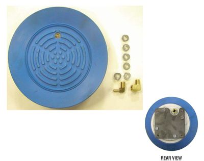
Draw Bar Pull / Vacuum (12” / 305 mm Round Cup) | 1,000 lb / 454 kg | 1,000 lb / 454 kg | 1,000 lb / 454 kg |
Draw Bar Pull Magnet* | 800 lb to 1,200 lb / 363 kg to 544 kg | 800 lb to 1,200 lb / 363 kg to 544 kg | 800 lb to 1,200 lb / 363 kg to 544 kg |
Vacuum Attach Time | < 1 s | < 1 s | < 1 s |
Vacuum Release Time | < 1 s | < 1 s | < 1 s |
Input Voltage | 480 V / 3 ph / 60Hz | 480 V / 3 ph / 60Hz | 480 V / 3 ph / 60Hz |
AC Current Draw | 45 A | 45 A | 45 A |
AC Current Draw w/ Electric Drive Option | 52 A | 52 A | 52 A |
Control Circuit Voltage | 120 V ac | 120 V ac | 120 V ac |
Hydraulic Power Unit | 25 hp / 18.7 kW | 25 hp / 18.7 kW | 25 hp / 18.7 kW |
Hydraulic Power Unit w/ Electric Drive Option | 30 hp / 22.4 kW | 30 hp / 22.4 kW | 30 hp / 22.4 kW |
Hydraulic Pump | 36 gal/min / 136 L/min | 36 gal/min / 136 L/min | 36 gal/min / 136 L/min |
Power Unit | Hydraulic, Variable Displacement | Hydraulic, Variable Displacement | Hydraulic, Variable Displacement |
Operating Pressure | 1,200 psi / 76 bar | 1,200 psi / 76 bar | 1,200 psi / 76 bar |
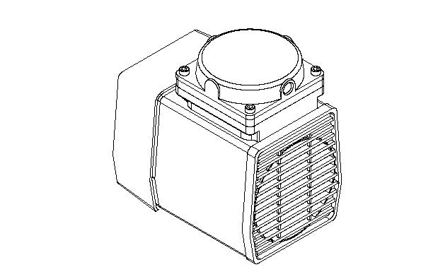
Vacuum Pump | 1/3 hp / 0.25 kW | 1/3 hp / 0.25 kW | 1/3 hp / 0.25 kW |
Vacuum | 21” Hg / 711 mbar | 21” Hg / 711 mbar | 21” Hg / 711 mbar |
Full Load Capacity | 10,000 lb / 4535 kg | 10,000 lb / 4535 kg | 10,000 lb / 4535 kg |
Weight (Empty) | 9,660 lb / 4382 kg | 9,960 lb / 4518 kg | 10,940 lb / 4962 kg |
Total Compartment Rollers / Powered | 11/5 | 11/5 | 11/5 |
Guide Track | 3” x 2.5” Angle 76 mm x 64 mm | 3” x 2.5” Angle 76 mm x 64 mm | 3” x 2.5” Angle 76 mm x 64 mm |
Overall Dimensions (L x W x H) | 168” x 74” x 223” 4267 mm x 1880 mm x 5665 mm | 192” x 74” x 223” 4877 mm x 1880 mm x 5665 mm | 204” x 74” x 223” 5182 mm x 1880 mm x 5665 mm |
Vacuum Arm Reach | 3.5” to 13” / 89 mm to 330 mm | 3.5” to 13” / 89 mm to 330 mm | 3.5” to 13” / 89 mm to 330 mm |
Vacuum Arm Reach (Hydraulic Extension) | 9” to 23” / 229 mm to 584 mm | 9” to 23” / 229 mm to 584 mm | 9” to 23” / 229 mm to 584 mm |
Magnet Arm Reach (Hydraulic Extension) Truck Side | 14” to 22” / 355 mm to 559 mm | 14” to 22” / 355 mm to 559 mm | 14” to 22” / 355 mm to 559 mm |
Wheel Base | 109” / 2769 mm | 133” / 3378 mm | 145” / 3683 mm |
Drive Wheel Centerline | 51” / 1295 mm | 51” / 1295 mm | 51” / 1295 mm |
Battery Compartment Width | 24” / 610 mm | 36” / 915 mm | 42” / 1067 mm |
Maximum Battery Dimensions (L x W x H) | 48” x 23” x 34” 1219 mm x 584 mm x 864 mm | 48” x 35” x 34” 1219 mm x 889 mm x 864 mm | 48” x 41” x 34” 1219 mm x 1041 mm x 864 mm |
Minimum Battery Width (with vacuum / magnet) | 12” / 305 mm 6” / 152 mm | 12” / 305 mm 6” / 152 mm | 12” / 305 mm 6” / 152 mm |
Minimum Battery Height | 17.75” / 451 mm | 17.75” / 451 mm | 17.75” / 451 mm |
Ground Clearance | 0.63” / 16 mm | 0.63” / 16 mm | 0.63” / 16 mm |
Roller Height | 6.5” Min / 136.75” Max 165 mm Min / 3473 mm Max | 6.5” Min / 136.75” Max 165 mm Min / 3473 mm Max | 6.5” Min / 136.75” Max 165 mm Min / 3473 mm Max |
PRE-INSTALLATION CHECK
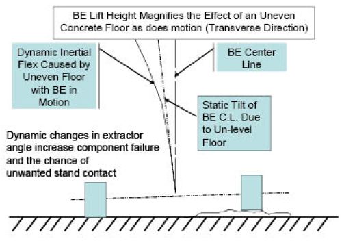
FLOOR CONDITIONS
The floor is the single most critical area of the battery room. A bad floor can cause significant issues with the installation as well as downtime and maintenance problems with the extractor. The floor should be verified as to its minimum thickness and strength with user. As noted on the drawing, the specific requirement of flatness for your particular type of system is listed. Below is a chart stating floor requirements. If possible, especially on double stack and higher systems, a digital level should be used to shoot the grade for compliance with the specification. The floor should also be inspected for severe cracks or excessively wide expansion joints in the travel path of the machine. If floor drains are present, they must not have a grade to the opening that encroaches into the travel path.
F-min is a rating method used to evaluate the flatness and levelness of a floor designated as "defined travel path". For example, an F-min rating of 60 means that there is no more than .129" of variation in the transverse axis (wheels left to right) and .287" variation in the longitudinal axis (front to back) on the equipment.
To avoid potential damage to drive wheel assemblies, guide track, structural components, guide rollers and issues with the inner frame equalization the "defined travel path" of the Battery Extractor should meet or exceed the recommended F-min specification. See chart below for the model specifications
Model | F-Min | +/- Longitudinal | +/- Transverse | Slope Defect |
SL, DS | 40 | .287" | .192" | .096" |
TS | 60 | .186" | .129" | .066" |
QS | 85 | .131" | .091" | .047" |
OPERATING CONTROLS & INSTRUCTIONS
OPERATING CONTROLS
OPERATOR CONSOLE
NOTE: Safety devices for the machine and the machine operating area shall not be rendered inoperable or misused.
SAFETY FEATURES
Key Switch – Located on the dash (see above). Primary on/off switch to prevent unauthorized personnel from operating the BE.
Emergency Stop – Located on the dash (see above). Will stop all functions immediately, locking all hydraulics in place. To use, press down on the red button. The machine key must be used to reset the emergency stop.
Foot Switch – Must be depressed to operate the BE. Stepping off the foot switch will stop all functions immediately, locking all hydraulics in place. To resume use, depress the foot switch.
Gate Switch – The gate must be fully closed for the BE to operate.
Extractor Arm Switch – Does not permit the machine to move forward or backward unless the extractor arm is located in the center of the carriage between the indicating arrows located on the arm guard.
Powered Roller Cutout – Disengages the powered roller function when the photo eye positioned on the edge of the BE battery compartment is disrupted by a battery, requiring additional input from the operator. Pressing the "Power Roller Cutout" override button (see above) on the dash will resume powered roller operation when loading or unloading batteries from the BE carriage.
Horn (If equipped) – Button located on the dash (see above). Used to alert personnel before moving the BE.
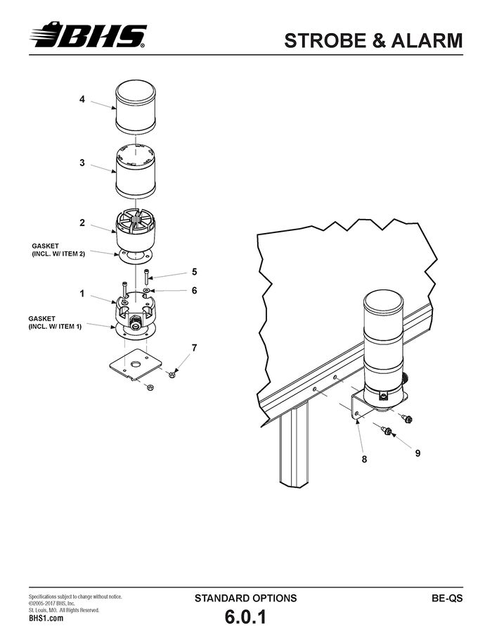
Strobe Light (If equipped) – Located on a vertical stanchion mounted to the right rear of the operator compartment. For units equipped with optional overhead guard (OHG), the beacon is located above of the operator compartment. Beacon automatically flashes when the BE is switched on.
Audible Alarm (if equipped) – Located in the same spot as the Strobe Light. Automatically sounds when the BE is switched on.
OPERATION OVERVIEW
• All operators should be familiar with the operator console of the extractor before performing any battery changes. The controls of the console are simple and well marked. It consists of six, manually operated, hydraulic control valves and a three position selector switch which controls the left and right vacuum cups (or optional magnets).
• The operator shall make certain there are no persons or obstacles in the extractor path prior to traveling forward or reverse.
• All manual valves are moved in the direction of the function travel which it controls with exception of the lift/lower valve, which is pulled toward the operator for "up" and pushed away for "down."
• In the event of any failure or malfunction, step off the dead-man switch and all functions will stop immediately, locking all hydraulics in place.
• The extractor arm must be in the center of the carriage or the unit will not travel forward or reverse.
• To ensure smooth operation, all valve movements should be made in a slow, deliberate motion.
• Only one key should be provided to operate the extractor.
• When leaving the machine, the operator shall turn off the key switch and remove the key to prevent unauthorized use.
• Ensure all the batteries and cables are properly stored in the battery stands prior to moving the BE.
• The BE is designed to carry only one battery in each compartment on the carriage.
• When loading the BE, position the batteries in the center of the compartments on the powered rollers to prevent any battery movement when transporting.
• Ensure there are no projections outside of the carriage before moving the BE.
OPERATING INSTRUCTIONS
PRE-CHANGE OUT PREPARATION
- Position lift truck for change out in designated area.
- Remove all battery restraints and disconnect battery cables following manufacturers guidelines. (Be sure to position battery cables so as not to be damaged by battery during change out.)
- Mount battery extractor and close safety gate. (Gate must be fully closed or unit will not operate.)
- Secure safety lanyard to safety harness.
- Depress foot-operated pedal. (Dead-man switch)
- Turn key switch to "ON" position.
NOTE: If unit fails to energize after steps 2-5, verify the Emergency Stop is not depressed.
DISCHARGED BATTERY REMOVAL
- Move extractor forward or reverse to position center of empty compartment with center of lift truck battery compartment. (Lead roller of extractor is equipped with a centering groove. Users may find it beneficial to mark center of lift truck compartment to aid in alignment.)
- Align extractor’s roller bed height with lift truck’s battery compartment.
- Rotate extractor arm into battery compartment aligned in Step 2.
- Move extractor arm toward battery until vacuum cup/ magnet contacts battery.
- Energize vacuum cup/magnet by turning selector switch to proper direction, left or right.
- Move extractor arm away from lift truck toward center of extractor roller bed, removing discharged battery. (Battery should be pulled past first three idler rollers onto first or second powered roller.)
- Turn off vacuum/magnet and move extractor arm away from battery 1" to 2".
- Rotate extractor arm out of battery compartment into opposite compartment (if empty) and center arm in carriage.
- Depress powered roller override button and move battery into center of compartment using powered rollers.
CHARGED BATTERY RETRIEVAL
- Locate charged battery of appropriate type for lift truck being changed.
- Move extractor to appropriate rack position and align empty roller compartment horizontally with center of bottom battery storage rack compartment. (Battery safety stop of each compartment is center of that compartment and should be used for alignment with groove in lead roller of battery extractor compartment.)
- Raise battery extractor roller compartment to proper level to gain access as needed to disconnect battery from charger.
- Adjust roller compartment height to battery being retrieved.
- Rotate arm into empty compartment (if not already positioned there.)
- Move extractor arm toward battery until vacuum cup/ magnet contacts battery.
- Energize vacuum cup/magnet by turning selector switch to proper direction, left or right.
- Move extractor arm away from battery rack toward center of extractor roller bed, removing charged battery. (Battery should be pulled past first three idler rollers onto first or second powered roller.)
- Turn off vacuum/magnet and move extractor arm away from battery 1" to 2".
- Rotate extractor arm out of battery compartment into fully vertical position.
- Depress powered roller override button and move battery into center of compartment using powered rollers.
DISCHARGED BATTERY RETURN
- While remaining at current battery compartment height, drive extractor to align roller compartment containing discharged battery with open battery compartment left by extraction of charged battery.
- Return discharged battery to battery rack using powered rollers. NOTE: In most instances, batteries can be deposited into battery racks in one motion using only powered rollers. When this does not work, the battery may need slight assistance from extractor arm. To do this, rotate arm into compartment such as one would if removing battery from rack. If extractor is vacuum equipped, position top edge of cup slightly higher than edge of battery (or over lifting eye if so equipped) to prevent cup from adhering to battery - No vacuum/magnet is necessary for pushing. DO NOT activate vacuum/magnet switch. Slowly push battery into rack until fully into compartment.
- Engage battery safety stop and connect battery to charger as required.
CHARGED BATTERY INSTALLATION
- Lower extractor roller compartment to fully lowered position.
- Return extractor back to lift truck and align roller compartment containing charged battery as performed in steps 1 & 2 of "Discharged Battery Removal".
- Move charged battery toward lift truck compartment by using powered rollers, verifying precise battery alignment.
- Adjust extractor vertically as well as horizontally, if needed.
- Insert battery into lift truck as far as possible using only the powered rollers.
- Rotate extractor arm into compartment and SLOWLY push battery into lift truck. (Be sure to watch battery cables for interference.)
- Drive extractor out of immediate area and carefully dismount the extractor.
- Secure newly installed battery in lift truck and reconnect battery cables.
- Return lift truck to service.
DO NOT drive the B.E. into the travel path end stops. The end stops are designed to prevent the B.E. from accidentally traveling beyond its designated travel path. Driving the B.E. into the end stops will cause the B.E. to stop suddenly, possibly causing damage to the end stop, the B.E. and/or personal injury.
MANUAL UNLOADING
Lockout/tagout and de-energize all equipment prior to manually unloading any battery.
In the event of power loss or an operational malfunction of the BE not allowing a battery to be unloaded using normal operating procedures, it is recommended a battery be removed from the BE using certified and approved vertical extraction methods and devices.
Read, understand and observe all safety warnings and procedures related to the vertical extraction device(s) being used.
Should the status of the BE not allow for safe vertical extraction due to position in the battery aisle, only repairs required to safely maneuver the BE to a position allowing for safe vertical extraction should be made. Once any batteries are safely unloaded, any remaining repairs can be made.
Extreme care should be taken when working under or around equipment supporting elevated loads. Unexpected movement of the equipment could cause the load and/or equipment to fall. ALWAYS be sure devices of adequate size and strength are in place to prevent any personnel working under the elevated load from being crushed. Serious personal injury or death will occur.
SPARE PARTS LIST
Refer to the appropriate Spare Parts Kit (vacuum equipped units - Pt# BE-SPKV-QS, magnet equipped units - Pt# BE-SPKM-QS) at the beginning of Section 8 for the list of items recommended by the factory to have on hand for BE-QS models to minimize any downtime due to minor breakdown that may occur under normal operating conditions.
BHS also offers a supplement hose kit (Pt# 80442001) which contains an assortment of hoses allowing any hose on the extractor to be replaced immediately with a temporary hose of equal length or longer. When the extractor is back up and running, the failed hose can be taken to have an exact replacement made. Once the new hose is made and installed, the temporary hose can be returned to the kit for future use.
Use only BHS approved replacement parts.
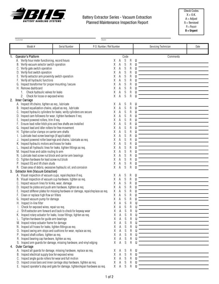
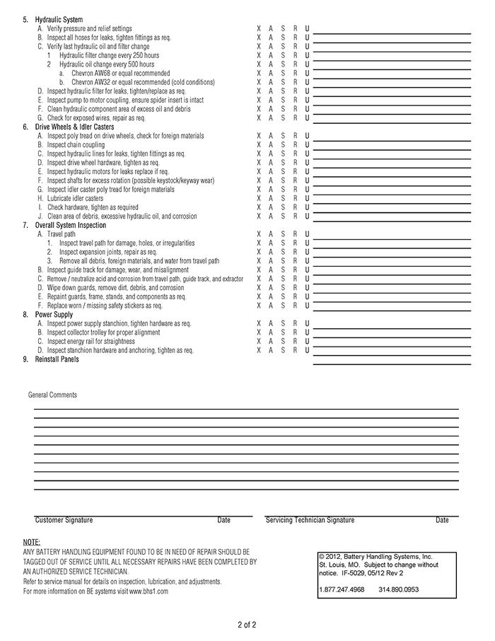
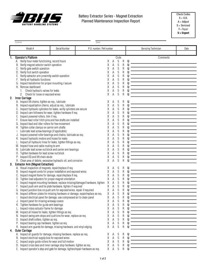
BHS recommends that a full maintenance inspection report similar to the one provided be done at least once a month.
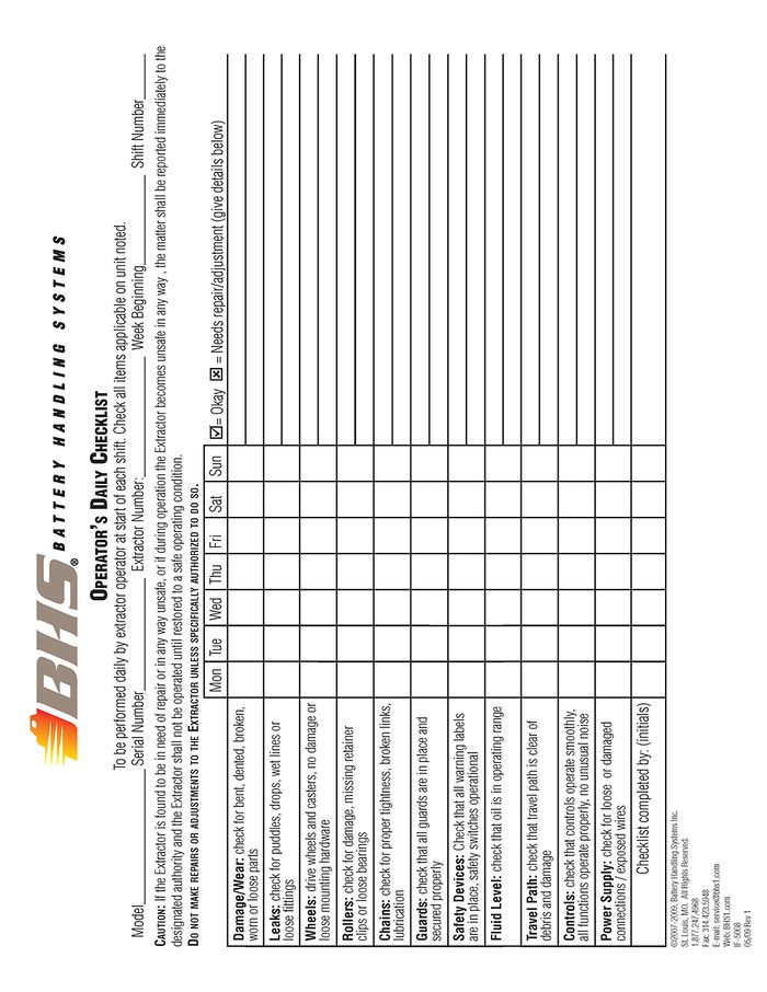
Any parts found to be excessively worn or damaged should promptly be replaced unless said parts pose a safety risk to the operator and/or extractor, in which case the unit should be removed from service until the problem(s) are remedied (See Operator’s Daily Checklist.)
Note: Spare parts kits contain parts for the most current machine design/configuration. Due to continuous design and manufacturing improvements, not all the parts in the spare parts kits may be compatible with older units. Consult factory when ordering spare parts for existing units in the field to ensure part compatibility.
PARTS SECTIONS
CHASSIS
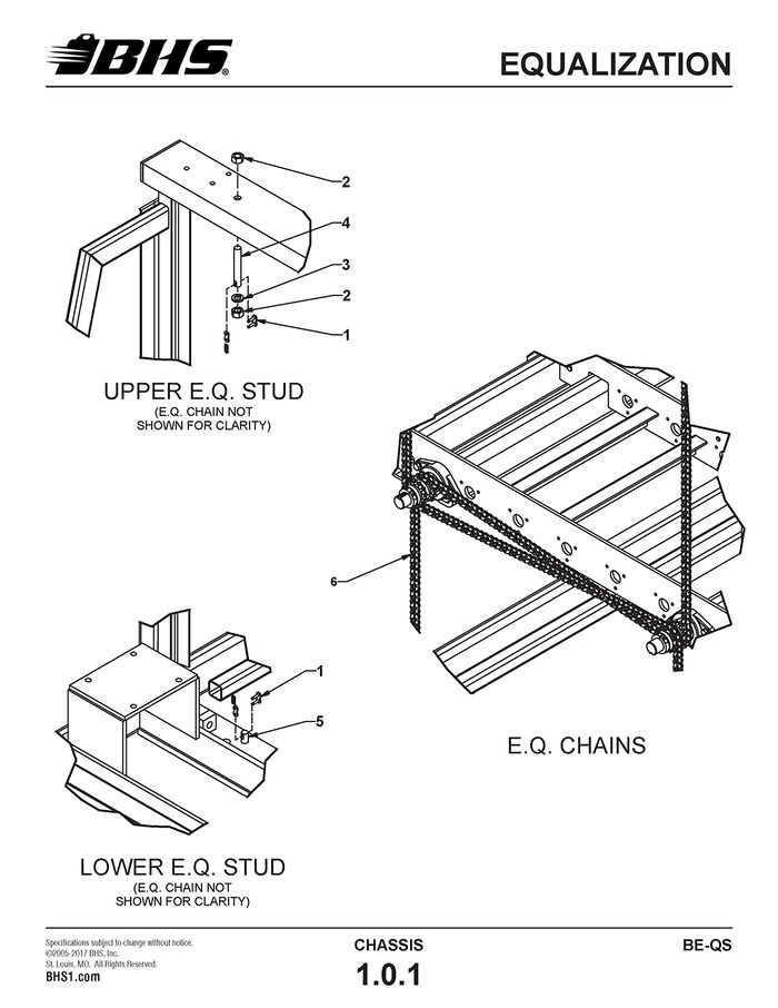
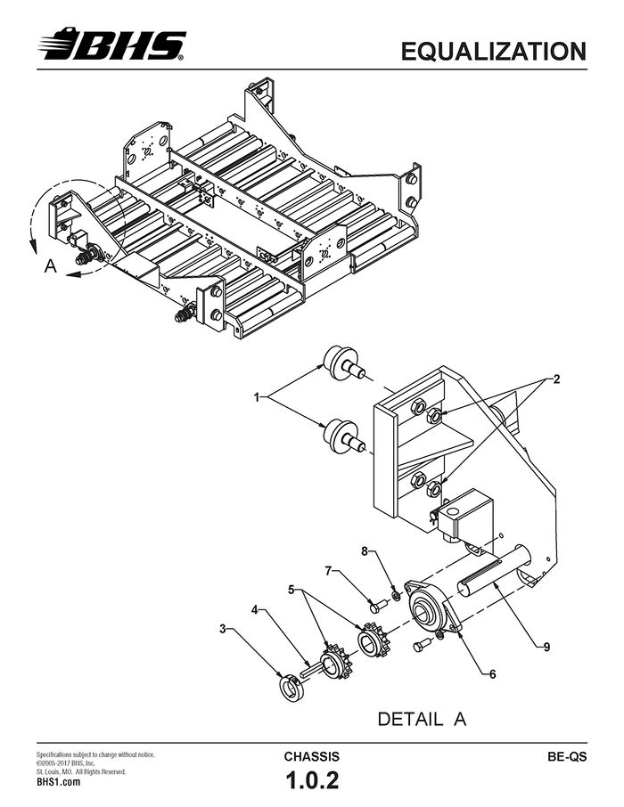
EQUALIZATION
ITEM | BHS PART NUMBER | DESCRIPTION | REF. KIT NO. | NOTES | NO. REQ |
1 | PT0222 | LINK-CONNECTING-#60 | 8 | ||
2 | HW0017 | NUT-HEX-3/4-10 | 8 | ||
3 | HW0115 | WASHER-LOCK-3/4" | 4 | ||
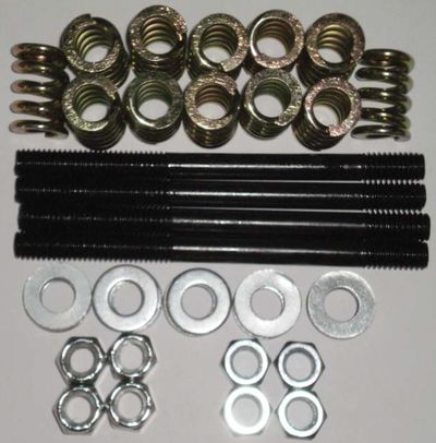
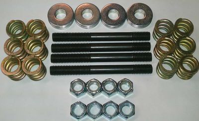
4 | 43097001 | STUD-ANCHOR-5" | UPPER | 4 | |
5 | 43097002 | STUD-ANCHOR-2" | LOWER | 4 | |
6 | 00158001-27 | CHAIN-ROLLER-#60 | 4 |
ITEM | BHS PART NUMBER | DESCRIPTION | REF. KIT NO. | NOTES | NO. REQ |
1 | PT0503 | BEARING-FLANGED LOAD-2 1/4" | 8 | ||
2 | HW0025 | NUT-JAM-7/8-14 | 8 | ||
3 | PT0416 | COLLAR-SHAFT-1 1/2" | 4 | ||
4 | 43097006 | KEY-3/8" X 2 3/4" | 4 | ||
5 | PT0224 | SPROCKET-60B12 X 1 1/2" | KEYED IN LINE | 8 | |
6 | PT0405 | FLANGE BEARING-2 BOLT-1 1/2" | 4 | ||
7 | HW0502 | BOLT-HHCS-1/2-13 X 1 1/4" | 8 | ||
8 | HW0110 | WASHER-LOCK-1/2" | 8 | ||
9 | 47027001 | SHAFT-EQUALIZATION-84.75" | BE-24-2-QS | 2 | |
47227001 | SHAFT-EQUALIZATION-108.75" | BE-36-2-QS | 2 | ||
47327001 | SHAFT-EQUALIZATION-120.75" | BE-42-2-QS | 2 |
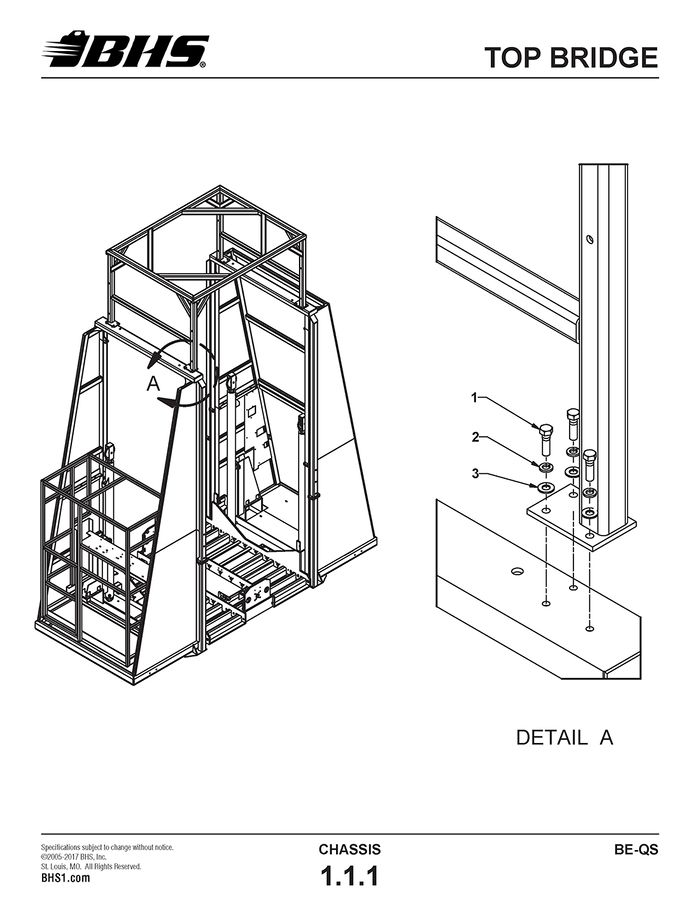
TOP BRIDGE
ITEM | BHS PART NUMBER | DESCRIPTION | REF. KIT NO. | NOTES | NO. REQ |
1 | HW0502 | BOLT-HHCS-1/2-13 X 1 1/4" | 12 | ||
2 | HW0110 | WASHER-LOCK-1/2" | 12 | ||
3 | HW0112 | WASHER-FLAT-1/2"-SAE | 12 |
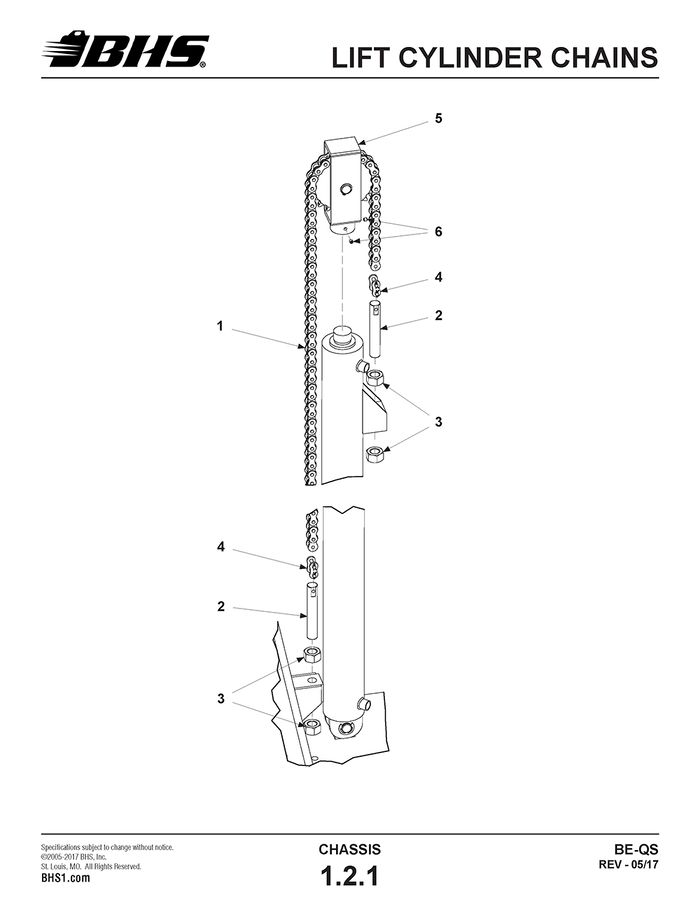
LIFT CYLINDER CHAINS
ITEM | BHS PART NUMBER | DESCRIPTION | REF. KIT NO. | NOTES | NO. REQ |
1 | 00158001-28 | CHAIN-ROLLER-#80 | 4 | ||
2 | 43897002 | STUD-LIFT-6" | 8 | ||
3 | HW0014 | NUT-HEX-1-8 | 12 | ||
4 | PT0204-1 | LINK-CONNECTING-#80 | 8 | ||
5 | 43922001 | CLEVIS ASSEMBLY | 4 | ||
6 | HW0813 | SCREW-SHSS-3/8-16 X 1/2" | NYLON TIPPED | 8 |
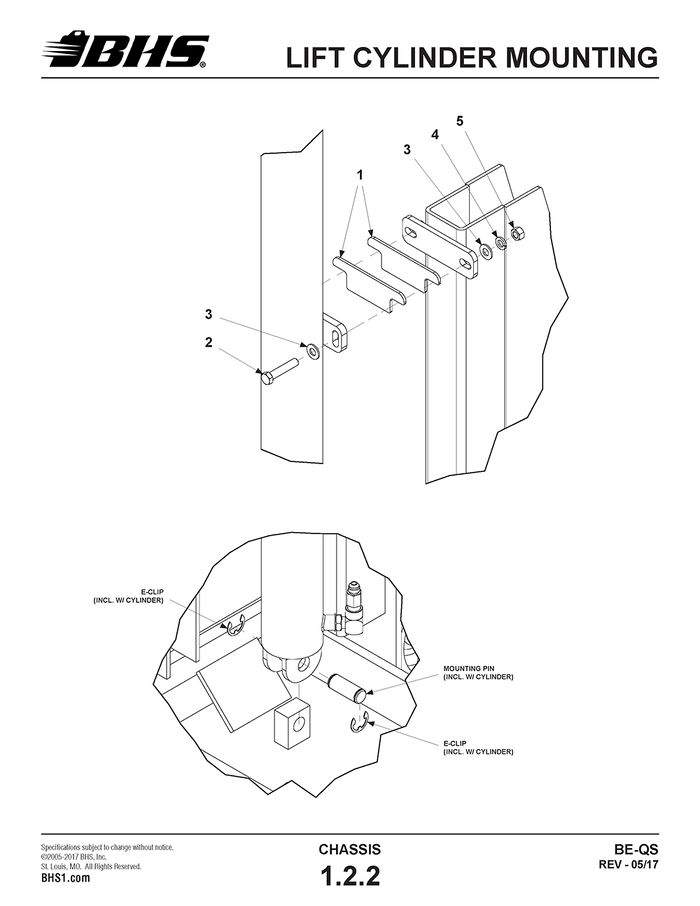
LIFT CYLINDER MOUNTING
ITEM | BHS PART NUMBER | DESCRIPTION | REF. KIT NO. | NOTES | NO. REQ |
1 | 41617109 | SHIM-CYLINDER-10 GA | .135" THICK | A/R | |
41617110 | SHIM-CYLINDER-14 GA | .075" THICK | A/R | ||
41617111 | SHIM-CYLINDER-3/16" | .188" THICK | A/R | ||
2 | HW0514 | BOLT-HHCS-1/2-13 X 2 1/2" | 8 | ||
3 | HW0112 | WASHER-FLAT-1/2"-SAE | 16 | ||
4 | HW0110 | WASHER-LOCK-1/2" | 8 | ||
5 | HW0007 | NUT-HEX-1/2-13 | 8 |
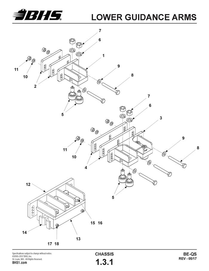
LOWER GUIDANCE ARMS
BHS PART NUMBER | DESCRIPTION | REF. KIT NO. | NOTES | NO. REQ | ||
1 | 43015011 | GUIDE ARM WELDMENT, 2 ROLLER | 2 | - | ||
2 | 43017025 | SPACER-GUIDE ARM | †1/2" THICK | 4 | - | |
3 | 41215204 | GUIDE ARM WELDMENT, 4 ROLLER | - | 2 | ||
4 | 41217274 | SPACER-GUIDE ARM | - | 4 | ||
5 | 43012007 | CAM ROLLER-1 3/4" | 4 | 8 | ||
6 | HW0115 | WASHER-LOCK-3/4" | 4 | 8 | ||
7 | HW0011 | NUT-HEX-3/4-16 | 4 | 8 | ||
8 | HW0516 | BOLT-HHCS-1/2-13 X 6 1/2" | 4 | 6 | ||
9 | HW0112 | WASHER-FLAT-1/2"-SAE | 4 | 6 | ||
10 | HW0110 | WASHER-LOCK-1/2" | 4 | 6 | ||
11 | HW0007 | NUT-HEX-1/2-13 | 4 | 6 | ||
12 | 41215234 | GUIDE ARM WELDMENT (POLY) | 2 | |||
13 | 41217317 | POLY SLIDE MOUNTING BLOCK | 4 | |||
14 | 41217318 | POLY SLIDE | 4 | |||
15 | HW0501 | BOLT-HHCS-1/2-13 x 1 | 6 | |||
16 | HW0110 | WASHER-LOCK-1/2" | 6 | |||
17 | 91253A546 | BOLT FHSCS-1/4-20 x 1-1/2 | 4 | |||
18 | HW0003 | NUT-NILN-1/4-20 | 4 | |||
† OLDER UNITS EQUIPPED WITH (1) 1" THICK SPACER PER GUIDE ARM BRACKET.
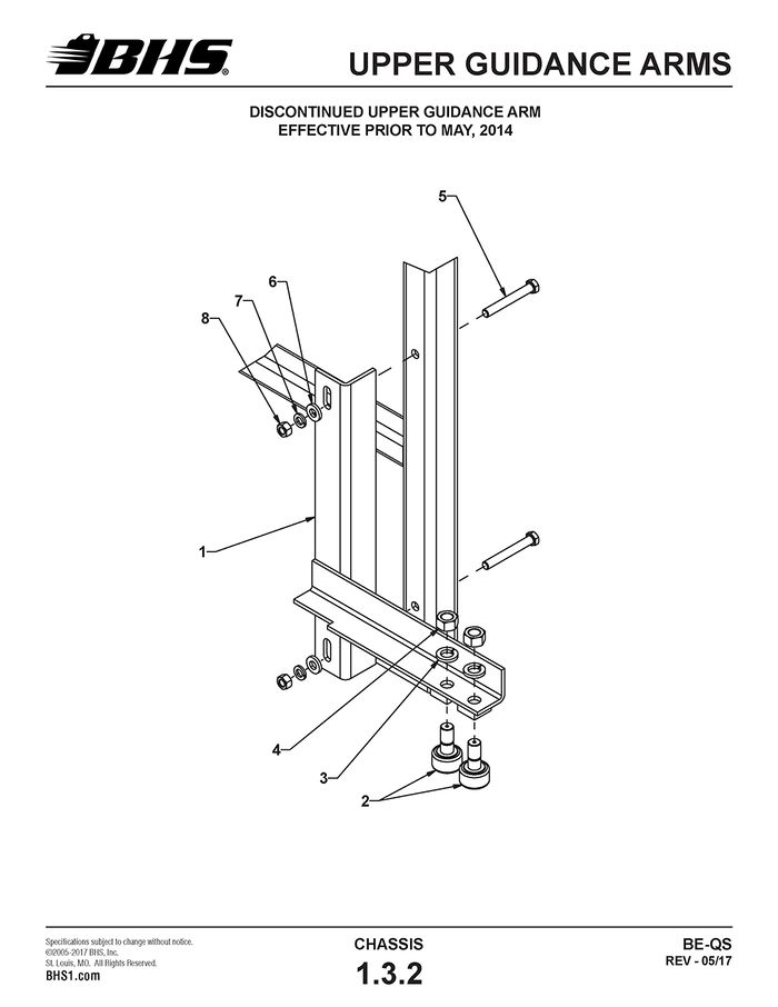
UPPER GUIDANCE ARMS
ITEM | BHS PART NUMBER | DESCRIPTION | REF. KIT NO. | NOTES | NO. REQ |
1 | 43915016 | GUIDE ARM WELDMENT-UPPER | USED PRIOR TO JAN, 2012 | 2 | |
43915024 | GUIDE ARM WELDMENT-UPPER | USED JAN, 2012 TO MAY, 2014 | 2 | ||
2 | 43012007 | CAM ROLLER-1 3/4" | 4 | ||
3 | HW0115 | WASHER-LOCK-3/4" | 4 | ||
4 | HW0011 | NUT-HEX-3/4-16 | 4 | ||
5 | HW0511 | BOLT-HHCS-1/2-13 X 3 3/4" | 4 | ||
6 | HW0112 | WASHER-FLAT-1/2"-SAE | 4 | ||
7 | HW0110 | WASHER-LOCK-1/2" | 4 | ||
8 | HW0007 | NUT-HEX-1/2-13 | 4 |
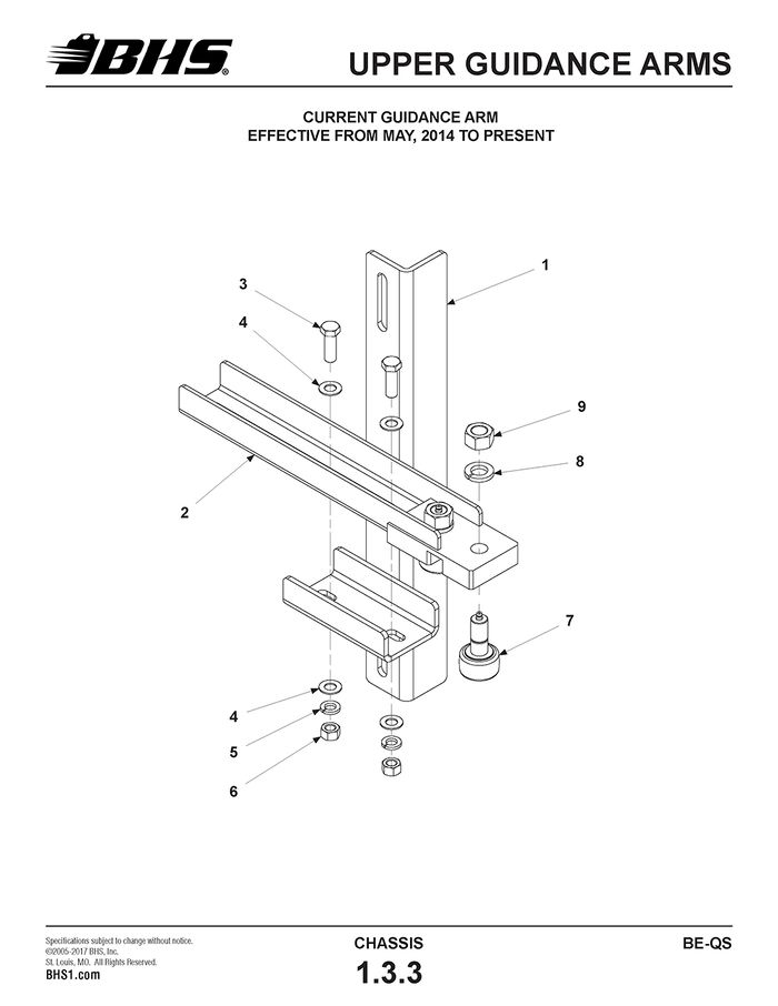
ITEM | BHS PART NUMBER | DESCRIPTION | REF. KIT NO. | NOTES | NO. REQ |
REF | 43912007 | GUIDE ARM ASSEMBLY | INCL. ITEMS 1 THRU 9 | 2 | |
1 | 43915025 | GUIDE ARM MOUNT | 2 | ||
2 | 43915026 | GUIDE ARM | 2 | ||
3 | HW0503 | BOLT-HHCS-1/2-13 X 1 1/2" | 4 | ||
4 | HW0112 | WASHER-FLAT-1/2"-SAE | 8 | ||
5 | HW0110 | WASHER-LOCK-1/2" | 4 | ||
6 | HW0007 | NUT-HEX-1/2-13 | 4 | ||
7 | 43012007 | CAM ROLLER-1 3/4" | 4 | ||
8 | HW0115 | WASHER-LOCK-3/4" | 4 | ||
9 | HW0011 | NUT-HEX-3/4-16 | 4 | ||
10 | HW0511 | BOLT-HHCS-1/2-13 X 3 3/4" | MOUNTING HARDWARE (NOT SHOWN) | 4 | |
11 | HW0112 | WASHER-FLAT-1/2"-SAE | 4 | ||
12 | HW0110 | WASHER-LOCK-1/2" | 4 | ||
13 | HW0007 | NUT-HEX-1/2-13 | 4 |
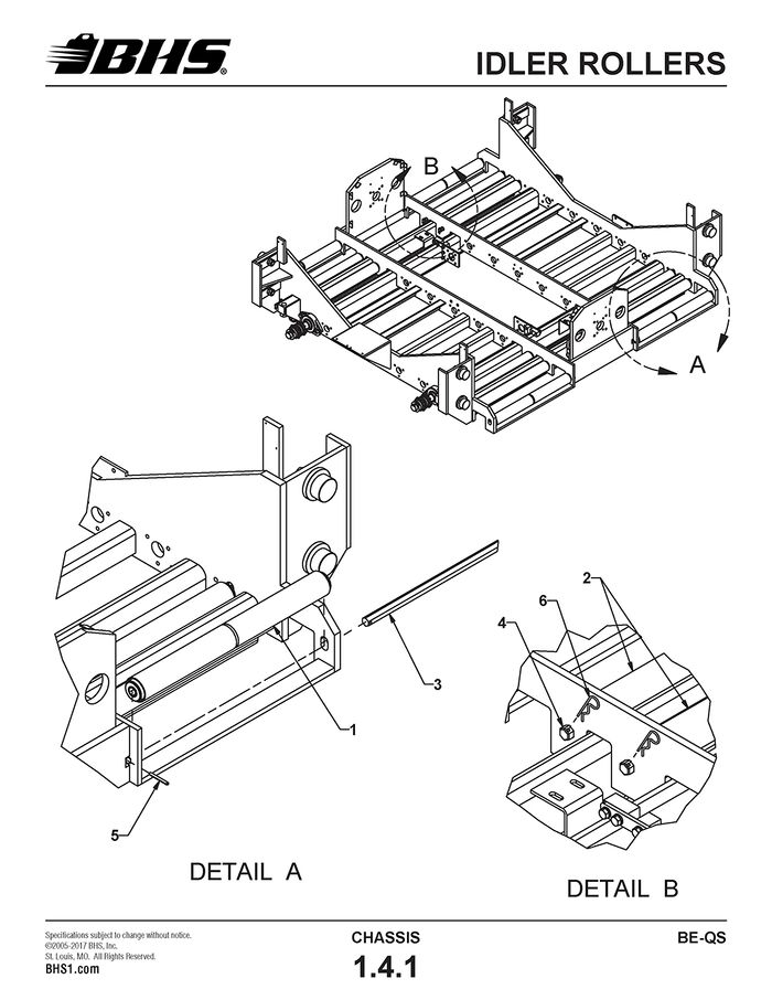
IDLER ROLLERS
ITEM | BHS PART NUMBER | DESCRIPTION | REF. KIT NO. | NOTES | NO. REQ |
1 | 43182001 | LEAD ROLLER ASSEMBLY-24" | W/ ALIGNMENT GROOVE | 4 | |
43382001 | LEAD ROLLER ASSEMBLY-36" | W/ ALIGNMENT GROOVE | 4 | ||
43482001 | LEAD ROLLER ASSEMBLY-42" | W/ ALIGNMENT GROOVE | 4 | ||
2 | 43182002 | IDLER ROLLER ASSEMBLY-24" | 8 | ||
43382002 | IDLER ROLLER ASSEMBLY-36" | 8 | |||
43482002 | IDLER ROLLER ASSEMBLY-42" | 8 | |||
3 | 47087001 | SHAFT-HEX-.75" X 25.625" | HOLE IN ONE END ONLY | 4 | |
47287001 | SHAFT-HEX-.75" X 37.625" | HOLE IN ONE END ONLY | 4 | ||
47387001 | SHAFT-HEX-.75" X 43.625" | HOLE IN ONE END ONLY | 4 | ||
4 | 43187003 | SHAFT-HEX-.75" X 27.5" | 8 | ||
43387003 | SHAFT-HEX-.75" X 39.5" | 8 | |||
43487003 | SHAFT-HEX-.75" X 45.5" | 8 | |||
5 | HW1046 | PIN-SPRING-1/4" X 2 1/4" | 4 | ||
6 | HW1058 | PIN-HITCH | 16 |
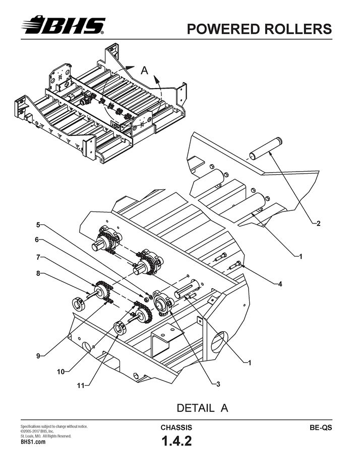
POWERED ROLLERS
ITEM | BHS PART NUMBER | DESCRIPTION | REF. KIT NO. | NOTES | NO. REQ |
1 | 43182003 | POWERED ROLLER-24" | 10 | ||
43382003 | POWERED ROLLER-36" | 10 | |||
43485003 | POWERED ROLLER-42" | 10 | |||
2 | 43087001 | JOURNAL-POWERED ROLLER | 10 | ||
3 | PT0404 | FLANGE BEARING-3-BOLT-1" | 20 | ||
4 | HW0336 HW0321 | BOLT-HHCS-5/16-18 X 1 3/8" BOLT-HHCS-5/16-18 X 1 1/4" | 15 15 | ||
5 | HW0105 | WASHER-LOCK-5/16" | 60 | ||
6 | HW0004 | NUT-HEX-5/16-18 | 60 | ||
7 | PT0033 | SPROCKET-35B18 X 1" | 16 | ||
8 | 00197028 | KEY-1/4" X 1 1/4" | 8 | ||
9 | 00158001-16 | CHAIN-ROLLER-#35 | 8 | ||
10 | PT0031 | LINK-CONNECTING-#35 | 8 |
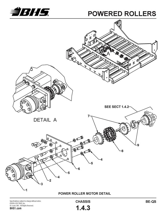
ITEM | BHS PART NUMBER | DESCRIPTION | REF. KIT NO. | NOTES | NO. REQ |
1 | HC0120 | MOTOR-HYDRAULIC-160CC | 2 | ||
2 | HW1071 | KEY-WOODRUFF-#808 STD | SUPPLIED WITH ITEM 1 | A/R | |
3 | H1544 | ADAPTER-#6 JICM X #10 SAEM | 4 | ||
4 | HW0402 | BOLT-HHCS-3/8-16 X 1" | 18 | ||
5 | HW0107 | WASHER-LOCK-3/8" | 18 | ||
6 | 43017004 | PLATE-MOTOR MOUNTING | 2 | ||
7 | PT0302-1 | COUPLING BODY-#40 X 1" | 4 | ||
8 | PT0301 | CHAIN-COUPLING-#40 | INCL. CONNECTING PIN | 2 | |
9 | 00197026 | KEY-1/4" X 1" | 4 |
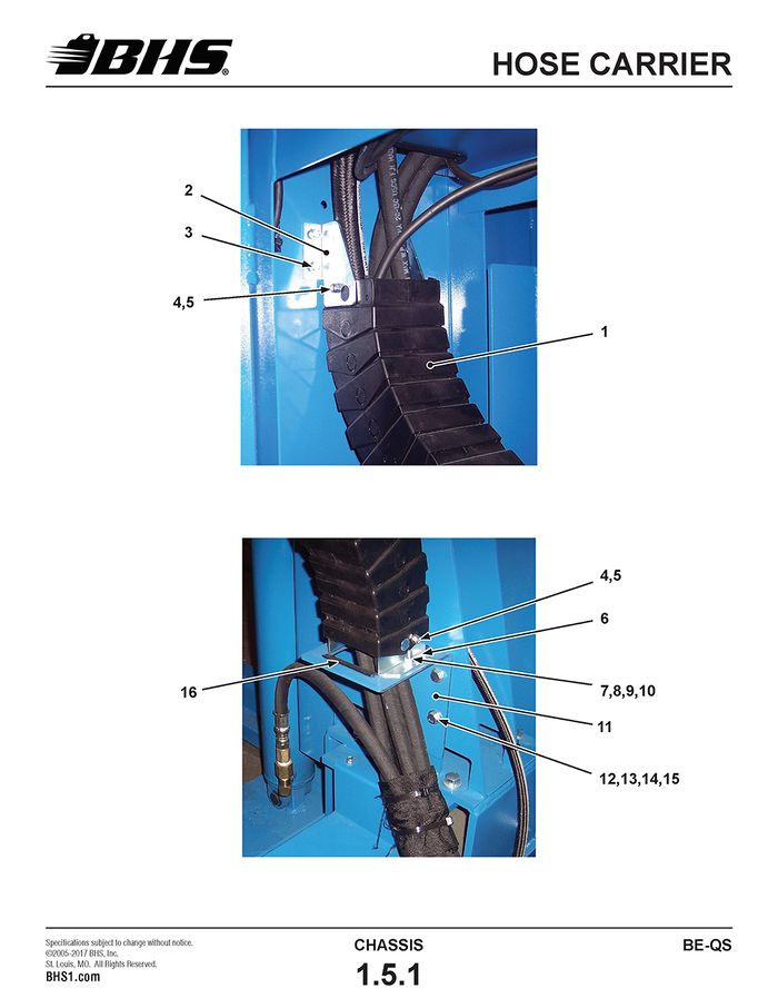
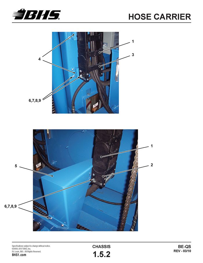
HOSE CARRIER
ITEM | BHS PART NUMBER | DESCRIPTION | REF. KIT NO. | NOTES | NO. REQ |
1 | PT0629 | CARRIER TRACK | 117 LINKS REQD | 14' | |
2 | PT0631 | BRACKET-UPPER MOUNTING | 1 | ||
3 | HW0301 | BOLT-SELF TAP "F"-1/4-20 X 1/2" | 8 | ||
4 | HW0212 | SCREW-RHMS-#10-24 X 1/2" | 4 | ||
5 | SS0202 | NUT-NILN-#10-24 | 4 | ||
6 | PT0630 | BRACKET-LOWER MOUNTING | 2 | ||
7 | HW0303 | BOLT-HHCS-1/4-20 X 1" | 2 | ||
8 | HW0103 | WASHER-LOCK-1/4" | 2 | ||
9 | HW0002 | NUT-HEX-1/4-20 | 2 | ||
10 | HW0104 | WASHER-FLAT-1/4"-SAE | 4 | ||
11 | 43917067-2 | BRACKET-HOSE CARRIER | 1 | ||
12 | HW0403 | BOLT-HHCS-3/8-16 X 1 1/4" | 4 | ||
13 | HW0107 | WASHER-LOCK-3/8" | 4 | ||
14 | HW0005 | NUT-HEX-3/8-16 | 4 | ||
15 | HW0108 | WASHER-FLAT-3/8"-SAE | 8 | ||
16 | PL0602 | VINYL EDGING | 2 PCS REQD (ONE NOT SHOWN) | 3.5" | |
17 | 43917056-2 | SUPPORT-HOSE CARRIER | 1 |
ITEM | BHS PART NUMBER | DESCRIPTION | REF. KIT NO. | NOTES | NO. REQ |
1 | PT0641 | CARRIER TRACK | 25 LINKS REQD | 8' | |
2 | PT0640 | LINK-END-MALE | SOLD AS SET | 1 | |
3 | LINK-END-FEMALE | 1 | |||
4 | 43917046-2 | BRACKET-HOSE CARRIER-OUTSIDE FRAME | 2 | ||
5 | 43915022 | BRACKET-HOSE CARRIER-INSIDE FRAME | 1 | ||
6 | HW0321 | BOLT-HHCS-5/16-18 X 1 1/4" | 18 | ||
7 | HW0106 | WASHER-FLAT-5/16"-SAE | 36 | ||
8 | HW0105 | WASHER-LOCK-5/16" | 18 | ||
9 | HW0004 | NUT-HEX-5/16-18 | 18 |
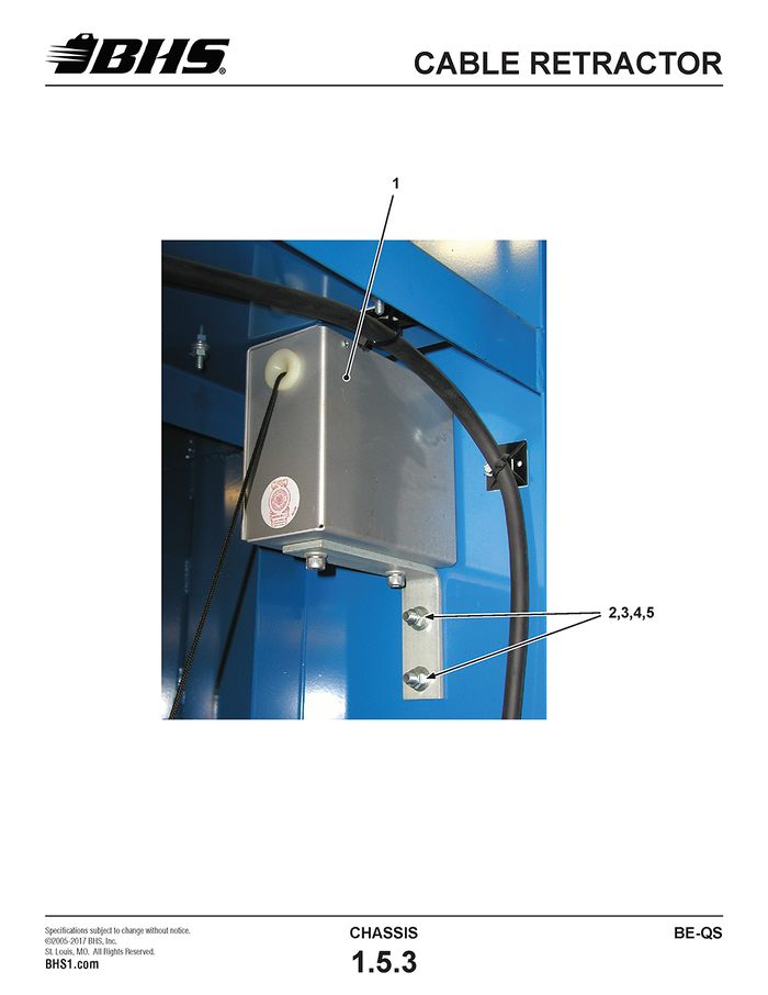
CABLE RETRACTOR
ITEM | BHS PART NUMBER | DESCRIPTION | REF. KIT NO. | NOTES | NO. REQ |
1 | CCR-12HD | TAKE UP REEL-CARRIER TRACK | 1 | ||
2 | HW0403 | BOLT-HHCS-3/8-16 X 1 1/4" | 2 | ||
3 | HW0108 | WASHER-FLAT-3/8"-SAE | 4 | ||
4 | HW0107 | WASHER-LOCK-3/8" | 2 | ||
5 | HW0005 | NUT-HEX-3/8-16 | 2 |
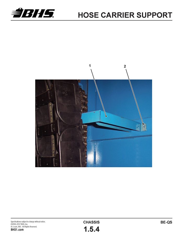
HOSE CARRIER SUPPORT
ITEM | BHS PART NUMBER | DESCRIPTION | REF. KIT NO. | NOTES | NO. REQ |
1 | 43917096-2 | SUPPORT-HOSE CARRIER | 1 | ||
2 | HW0301 | BOLT-SELF TAP "F"-1/4-20 X 1/2" | 2 |
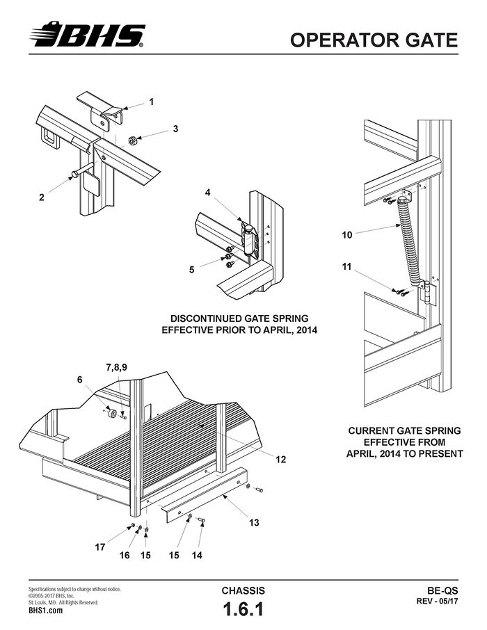
OPERATOR GATE
ITEM | BHS PART NUMBER | DESCRIPTION | REF. KIT NO. | NOTES | NO. REQ |
1 | 43017064-2 | LATCH-SWING GATE | 1 | ||
2 | HW0030 | BOLT-HHCS-3/8-16 X 2 1/4" | 1 | ||
3 | HW0031 | NUT-LOCK-3/8-16 | 1 | ||
4 | N/A | HINGE-SPRING | † SEE NOTES | 1 | |
5 | HW0301 | BOLT-SELF TAP "F"-1/4-20 X 1/2" | 3 | ||
6 | HW1037 | STOP-GATE | 80092001 | 1 | |
7 | HW0303 | BOLT-HHCS-1/4-20 X 1" | 80092001 | 1 | |
8 | HW0104 | WASHER-FLAT-1/4"-SAE | 80092001 | 1 | |
9 | HW0003 | NUT-NILN-1/4-20 | 80092001 | 1 | |
10 | HW9001 | SPRING-TORSION | 80292008 | 1 | |
11 | HW0816 | SCREW-HHCS-SELF DRILLING-#10 X 3/4" | 80292008 | 4 | |
12 | 43806001 | ANTI-FATIGUE MAT | 1 | ||
13 | 43017058-2 | THRESHOLD | 1 | ||
14 | HW0402 | BOLT-HHCS-3/8-16 X 1" | 2 | ||
15 | HW0108 | WASHER-FLAT-3/8"-SAE | 4 | ||
16 | HW0107 | WASHER-LOCK3/8" | 2 | ||
17 | HW0005 | NUT-HEX-3/8-16 | 2 |
† PART DISCONTINUED. SPRING HINGE MUST BE REPLACED WITH TORSION SPRING KIT
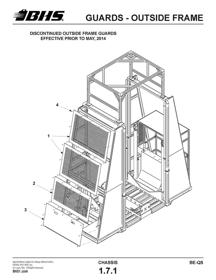
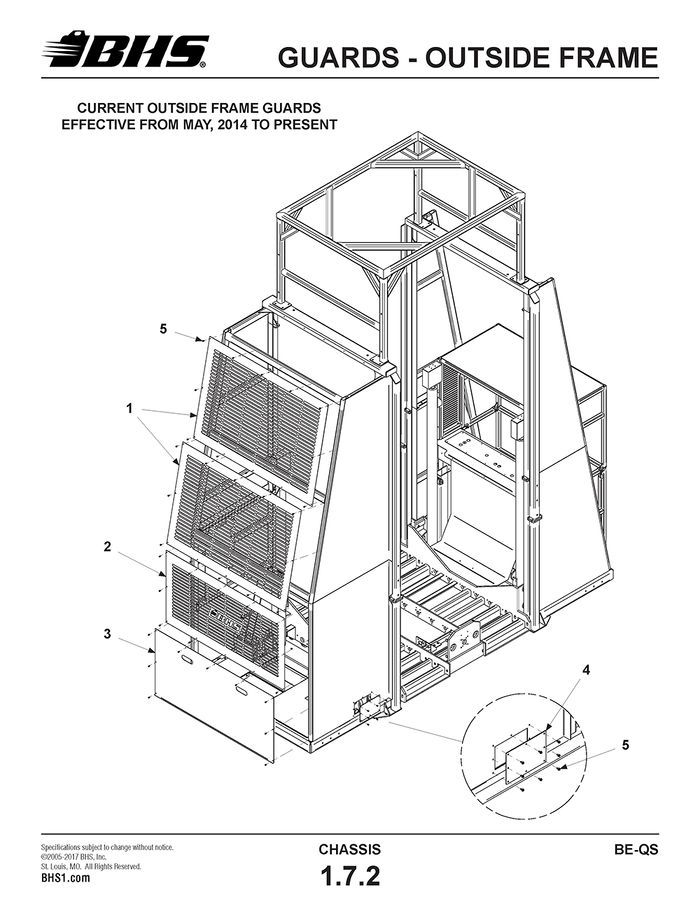
GUARDS - OUTSIDE FRAME
ITEM | BHS PART NUMBER | DESCRIPTION | REF. KIT NO. | NOTES | NO. REQ |
1 | 41617030 | GUARD-FAR END-UPPER | 2 | ||
2 | 41617031 | GUARD-FAR END-CENTER | 1 | ||
3 | 41617021-2 | GUARD-FAR END-LOWER | 1 | ||
4 | HW0301 | BOLT-SELF TAP "F"-1/4-20 X 1/2" | 49 |
ITEM | BHS PART NUMBER | DESCRIPTION | REF. KIT NO. | NOTES | NO. REQ |
1 | 41617030 | GUARD-FAR END-UPPER | 2 | ||
2 | 43918022 | GUARD-FAR END-CENTER | 1 | ||
3 | 41617021-2 | GUARD-FAR END-LOWER | 1 | ||
4 | 43918024 | PLATE-ACCESS-CASTER | 2 | ||
5 | HW0301 | BOLT-SELF TAP "F"-1/4-20 X 1/2" | 65 |
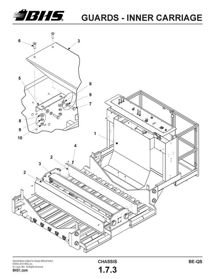
GUARDS - INNER CARRIAGE
ITEM | BHS PART NUMBER | DESCRIPTION | REF. KIT NO. | NOTES | NO. REQ |
1 | 43917043-2 | GUARD-FRONT-OPERATOR CONSOLE | 1 | ||
2 | 43017010-2 | GUARD-SIDE-ARM CARRIER SHAFT | 2 | ||
3 | 43014006-2 | GUARD-LINEAR DRIVE SCREW | 1 | ||
4 | HW0301 | BOLT-SELF TAP "F"-1/4-20 X 1/2" | A/R | ||
5 | 43017009-2 | BRACKET-SCREW GUARD MOUNTING | 2 | ||
6 | HW0306 | BOLT-FHSCS-1/4-20 X 1" | 4 | ||
7 | HW0303 | BOLT-HHCS-1/4-20 X 1" | 4 | ||
8 | HW0104 | WASHER-FLAT-1/4"-SAE | 8 | ||
9 | HW0103 | WASHER-LOCK-1/4" | 8 | ||
10 | HW0002 | NUT-HEX-1/4-20 | 4 |
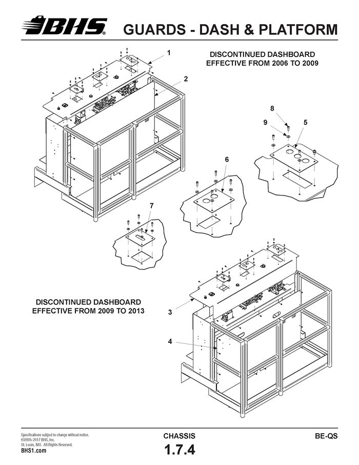
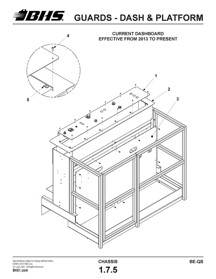
GUARDS - DASH & PLATFORM
ITEM | BHS PART NUMBER | DESCRIPTION | REF. KIT NO. | NOTES | NO. REQ |
1 | † | DASHBOARD-OPERATOR CONSOLE | USED APRIL, 2006 TO SEPT, 2009 | 1 | |
2 | 43817040 | KICK PLATE-OPERATOR CONSOLE | 41.5" HIGH | 1 | |
3 | 43917061-2 | DASHBOARD-OPERATOR CONSOLE | USED SEPT, 2009 TO FEB, 2013 | 1 | |
4 | 43817088 | KICK PLATE-OPERATOR CONSOLE | 33.5" HIGH | 1 | |
5 | 43617039 | COVER PLATE-VALVE-RHS | 1 | ||
6 | 43917062 | COVER PLATE-VALVE-CENTER | 1 | ||
7 | 43907094 | COVER PLATE-VALVE-LHS | 1 | ||
8 | SS0104 | BOLT-SHCS-1/4-20 X 5/8" | 12 | ||
9 | SS0300 | WASHER-FLAT-1/4"-SAE | 12 | ||
10 | PL0602 | VINYL EDGING | AT FOOT SWITCH - NOT SHOWN | 1’ | |
11 | HW0301 | BOLT-SELF TAP “F”-1/4-20 X 1/2" | DASH & KICK PLATE MTG BOLTS | A/R |
† CONSULT FACTORY FOR DASHBOARDS ON UNITS BUILT PRIOR TO 2009.
ITEM | BHS PART NUMBER | DESCRIPTION | REF. KIT NO. | NOTES | NO. REQ |
1 | A/R | PLATE-DASHBOARD | †USED FEB, 2013 TO PRESENT | 1 | |
2 | 43917105-2 | FRAME-DASHBOARD | 1 | ||
3 | 43817088 | KICK PLATE-OPERATOR CONSOLE | 33.5" HIGH | 1 | |
4 | HW0060 | NUT-CLIP-#10-24 | 12 | ||
5 | SS0114 | BHSC-#10-24 X 1/2"-SST | 12 | ||
6 | HW0301 | BOLT-SELF TAP “F”-1/4-20 X 1/2" | FRAME & KICK PLATE MTG BOLTS | A/R | |
7 | PL0602 | VINYL EDGING | AT FOOT SWITCH - NOT SHOWN | 1’ |
† CONSULT FACTORY
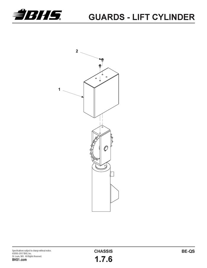
GUARDS - LIFT CYLINDER
ITEM | BHS PART NUMBER | DESCRIPTION | REF. KIT NO. | NOTES | NO. REQ |
1 | 43915017 | GUARD-CLEVIS | 4 | ||
2 | HW0301 | BOLT-SELF TAP "F"-1/4-20 X 1/2" | 8 |
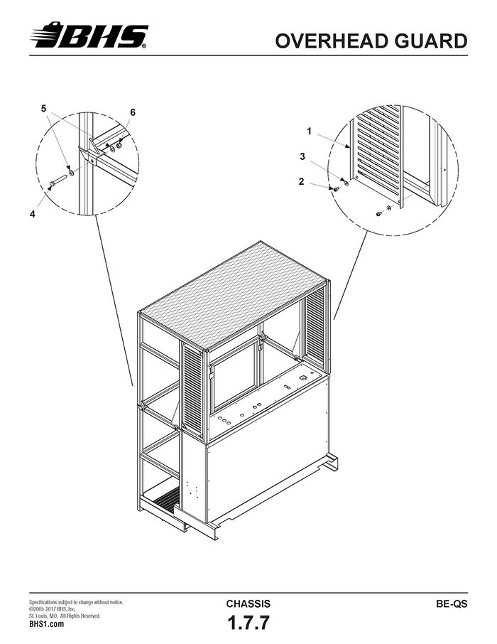
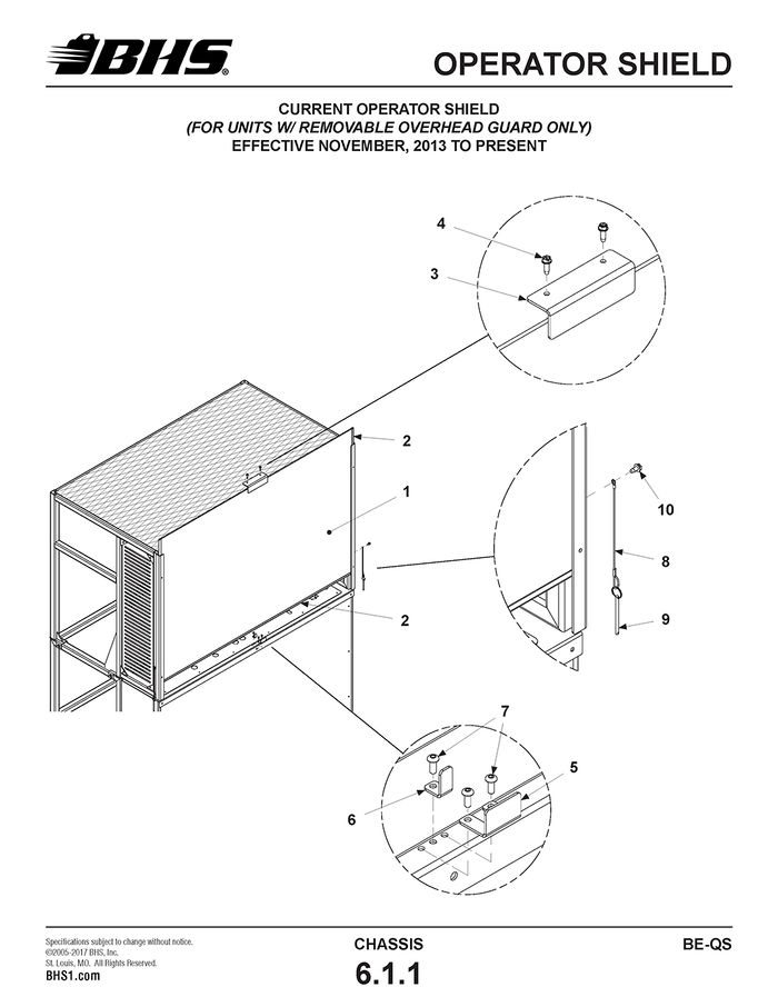
OVERHEAD GUARD
ITEM | BHS PART NUMBER | DESCRIPTION | REF. KIT NO. | NOTES | NO. REQ |
1 | 43817119-2 | GUARD-SIDE | †SEE NOTES | 2 | |
2 | HW0301 | BOLT-SELF TAP "F"-1/4-20 X 1/2" | 8 | ||
3 | HW0104 | WASHER-FLAT-1/4"-SAE | 8 | ||
4 | HW0406 | BOLT-HHCS-3/8-16 X 2-1/2" | 5 | ||
5 | HW0108 | WASHER-FLAT-3/8" | 10 | ||
6 | HW0006 | NUT-NILN-3/8-16 | 5 |
† SIDE GUARDS USED ON UNITS BUILT NOVEMBER, 2013 TO PRESENT. MOUNTING HARDWARE VALID FOR ALL UNITS W/ REMOVABLE OVERHEAD GUARD.
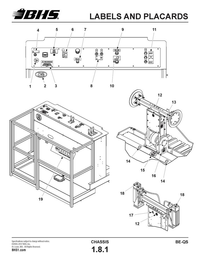
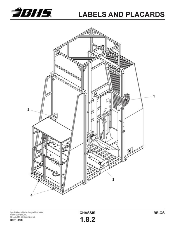
LABELS AND PLACARDS
ITEM | BHS PART NUMBER | DESCRIPTION | REF. KIT NO. | NOTES | NO. REQ |
1 | 00196612 | LABEL-"READ INSTRUCTION MANUAL PRIOR TO USE" | 1 | ||
2 | 00196616 | LABEL-"NO RIDERS ALLOWED" | 1 | ||
3 | 00196210 | LABEL-WARNING-"OPERATION BY AUTHORIZED PERSONNEL ONLY" | 1 | ||
4 | 43696001 | PLACARD-OFF / ON | 1 | ||
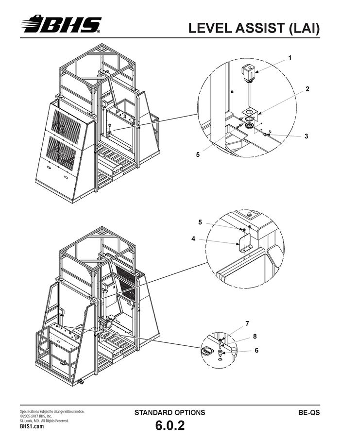
5 | 43096018 | PLACARD-RACK LEVEL ASSIST | †IF EQUIPPED | 1 | |
6 | 43096015 | PLACARD-PLATFORM RAISE / LOWER | 1 | ||
7 | 43096010 | PLACARD-HORN | †IF EQUIPPED | 1 | |
8 | 43096016 | PLACARD-DRIVE / ARM ROTATION | 1 | ||
9 | 43096012 | PLACARD-VACUUM OFF / ON | VACUUM EQP’D UNITS ONLY | 1 | |
43096011 | PLACARD-MAGNET OFF / ON | MAG UNITS ONLY (NOT SHOWN) | 1 | ||
10 | 43096017 | PLACARD-POWERED ROLLER CUTOUT OVERRIDE | 1 | ||
11 | 43096013 | PLACARD-POWERED ROLLERS / ARM TRAVERSE | 1 | ||
12 | 00196615 | LABEL-"DO NOT OPERATE WITH GUARDS REMOVED" | (1) PER SIDE OF ARM | 2 | |
13 | 00196633 | LABEL-NOTICE-"IN LINE VACUUM FILTER..." | (1) PER SIDE (VAC UNITS ONLY) | 2 | |
14 | SM-1197 | LABEL-ARM POSITION ARROW | 2 | ||
15 | 00196609 | LABEL-NOTICE-"ARM MUST BE POSITIONED BETWEEN ARROWS..." | 1 | ||
16 | 00196602 | LABEL-NOTICE-"LUBRICATION POINTS ON UNDERSIDE" | 2 | ||
17 | 00196218 | LABEL-WARNING-"ELECTRICAL VOLTAGE HAZARD" | MAGNET UNITS ONLY | 1 | |
18 | 00196214 | LABEL-WARNING-"STRONG MAGNETIC FIELD" | MAGNET UNITS ONLY | 2 | |
19 | 00196700 | DECAL-BHS-24" X 7.875" | 1 |
† RACK LEVEL ASSIST (LAI) AND HORN ARE OPTIONAL FEATURES. NOT ALL UNITS ARE EQUIPPED WITH THESE OPTIONS.
ITEM | BHS PART NUMBER | DESCRIPTION | REF. KIT NO. | NOTES | NO. REQ |
1 | 00196004 | LABEL-CAUTION-"WATCH FOR BATTERY AND CHARGER CABLES IN TRAVEL PATH" | 1 | ||
2 | 00196216 | LABEL-WARNING-"CHAIN ENTANGLEMENT HAZARD" | (1) PER CLEVIS GUARD | 4 | |
3 | 00196615 | LABEL-"DO NOT OPERATE WITH GUARDS REMOVED" | (1) EA. NEAR AND FAR GUARDS | 2 | |
4 | 00196622 | LABEL-LIFT POINT | (2) EACH END | 4 | |
5 | 00196700 | DECAL-BHS-24" X 7.875" | FAR END, NOT SHOWN | 1 | |
6 | 00196630 | LABEL-NOTICE-HYD. OIL SPEC. (AW 68) | † NOT SHOWN | 1 | |
00196645 | LABEL-NOTICE-HYD. OIL SPEC. (AW 32) | † NOT SHOWN | 1 |
† MOST UNITS SHIPPED PRIOR TO DECEMBER, 2014 REQUIRE AW 68 HYDRAULIC OIL. SOME UNITS SHIPPED PRIOR TO DECEMBER, 2014 SHIPPED WITH AW 32 FOR LOW TEMPERATURE APPLICATIONS.
EXTRACTOR ARM
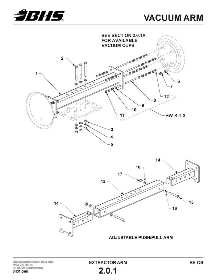
VACUUM ARM
ITEM | BHS PART NUMBER | DESCRIPTION | REF. KIT NO. | NOTES | NO. REQ |
1 | N/A | ARM-PUSH/PULL-30" | † DISCONTINUED | 1 | |
N/A | ARM-PUSH/PULL-36" | † DISCONTINUED | 1 | ||
2 | HW0509 | BOLT-HHCS-1/2-13 X 4 1/2" | 3 | ||
3 | HW0112 | WASHER-FLAT-1/2"-SAE | 6 | ||
4 | HW0110 | WASHER-LOCK-1/2" | 3 | ||
5 | HW0007 | NUT-HEX-1/2-13 | 3 | ||
6 | P0505 | BUSHING-RED-#6 NPT X #4 FNPT-BRASS | 2 | ||
7 | P0402 | HOSE BARB-1/4 X #4 MNPT-BRASS | 2 | ||
8 | HW0428 | STUD-VACUUM-3/8-16 X 5" | HW-KIT-2 | 8 | |
9 | HW0108 | WASHER-FLAT-3/8"-SAE | HW-KIT-2 | 40 | |
10 | HW1001 | SPRING-3/8" | HW-KIT-2 | 24 | |
11 | HW0006 | NUT-NILN-3/8-16 | HW-KIT-2 | 8 | |
12 | HW0424 | NUT-JAM-3/8-16 | HW-KIT-2 | 8 | |
REF | 43052006 | ADJUSTABLE PUSH/PULL ARM | INCL. ITEMS 13 THRU 17 | 1 | |
13 | 43057034 | ARM BASE | 1 | ||
14 | 43055008 | VACUUM CUP MOUNT | 2 | ||
15 | HW0523 | BOLT-HHCS-1/2-13 X 4" | 2 | ||
16 | HW0112 | WASHER-FLAT-1/2"-SAE | 4 | ||
17 | HW0008 | NUT-NILN-1/2-13 | 2 |
† ONE-PIECE ARMS NO LONGER AVAILABLE. MUST REPLACE WITH ADJUSTABLE ARM.
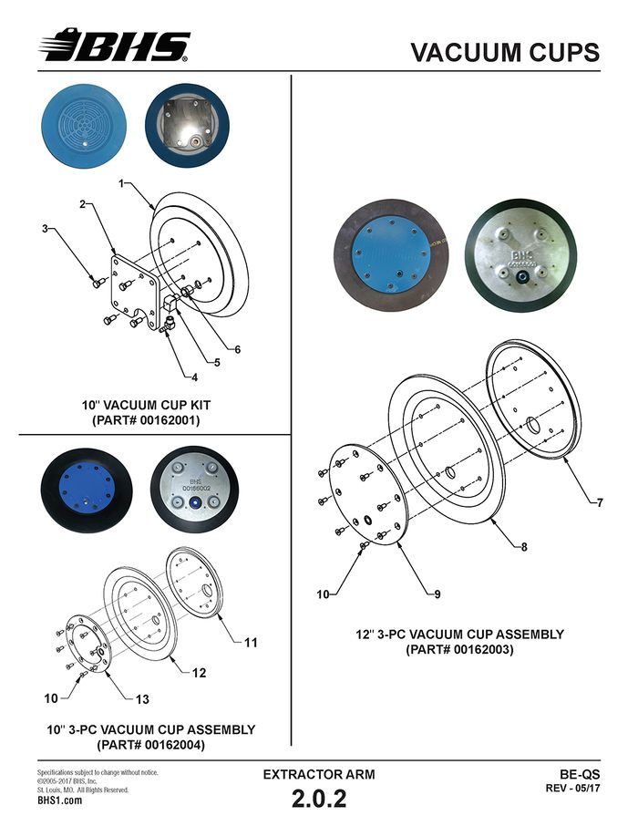
VACUUM CUPS
ITEM | BHS PART NUMBER | DESCRIPTION | REF. KIT NO. | NOTES | NO. REQ |
1 | N/A | VACUUM CUP-10" ROUND | 00162001 | † AVAILABLE IN KIT ONLY | A/R |
2 | 00117059 | PLATE-VACUUM CUP ADAPTER | 00162001 | 1 | |
3 | HW0328 | BOLT-HHCS-5/16-18 X 3/4" | 00162001 | 4 | |
4 | P0401 | ELBOW-#4 MNPT X 1/4" BARB-BRASS | 00162001 | 1 | |
5 | P0506 | ELBOW-STR-90 DEG-#4 NPT-BRASS | 00162001 | 1 | |
6 | P0505 | BUSHING-RED-#6 NPT X #4 FNPT-BRASS | 00162001 | 1 | |
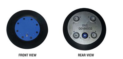
REF | 00162003 | VACUUM CUP-12" 3-PC | INCL. ITEMS 7 THRU 10 | A/R | |
7 | 00166001 | CASTING-12" VACUUM CUP | 00162003 | 1 | |
8 | 00164001 | SEAL-RUBBER-12" | 00162003 | 1 | |
9 | 00165001 | PLATE-FRONT-12" | 00162003 | 1 | |
10 | HW0311 | BOLT-FHSCS-1/4-20 X 3/4" | 00162003 | 8 | |
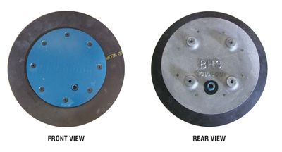
REF | 00162004 | VACUUM CUP-10" 3-PC | INCL. ITEMS 10 THRU 13 | A/R | |
11 | 00164006 | CASTING-10" VACUUM CUP | 00162004 | 1 | |
12 | 00164004 | SEAL-RUBBER-10" | 00162004 | 1 | |
13 | 00165002 | PLATE-FRONT-10" | 00162004 | 1 |
† ONE-PIECE CONSTRUCTION
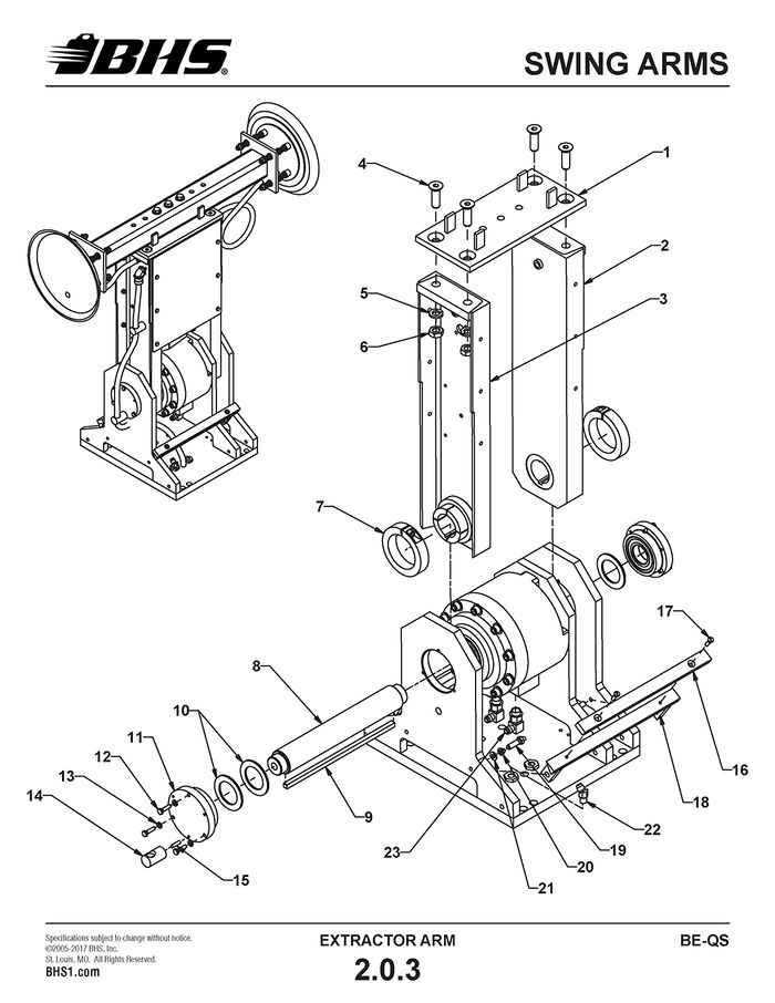
SWING ARMS
ITEM | BHS PART NUMBER | DESCRIPTION | REF. KIT NO. | NOTES | NO. REQ |
1 | 45055001 | TIE PLATE-SWING ARM | BE-24 | 1 | |
45255001 | TIE PLATE-SWING ARM | BE-36 (NOT SHOWN) | 1 | ||
45355001 | TIE PLATE-SWING ARM | BE-42 (NOT SHOWN) | 1 | ||
2 | 43055004 | SWING ARM-RHS | † | NOT SOLD INDIVIDUALLY | 1 |
3 | 43055002 | SWING ARM-LHS | † | NOT SOLD INDIVIDUALLY | 1 |
4 | HW0603 | BOLT-FHSCS-5/8-11 X 2" | 4 | ||
5 | HW0113 | WASHER-LOCK-5/8" | 4 | ||
6 | HW0010 | NUT-JAM-5/8-11 | 4 | ||
7 | PT0413 | COLLAR-SHAFT-3" | 80252001 | 2 | |
8 | 43027001 | SHAFT-ROTARY ACTUATOR | 80252001 | 1 | |
9 | HW1013 | KEY-3/8" X 12" | 80252001 | 1 | |
10 | PT0419 | BEARING-SAE 841-2" ID, 3" OD, 1/8" THICK | 80252001 | 3 | |
11 | 43052005 | CAP-BEARING | INCLUDES BEARING | 2 | |
12 | HW0303 | BOLT-HHCS-1/4-20 X 1" | 6 | ||
13 | HW0103 | WASHER-LOCK-1/4" | 6 | ||
14 | 43057014 | STANDOFF-WIRE | 1 | ||
15 | HW0312 | SCREW-SHSS-1/4-20 X 1"-CUP POINT | 1 | ||
16 | 43057003 | CUSHION-SWING ARM | 2 | ||
17 | HW0306 | BOLT-FHSCS-1/4-20 X 1" | 4 | ||
18 | 43055001 | STOP-SWING ARM | 2 | ||
43057008 | SPACER-SWING ARM STOP | NOT SHOWN | 2 | ||
19 | HW0403 | BOLT-HHCS-3/8-16 X 1 1/4" | 4 | ||
20 | HW0107 | WASHER-LOCK-3/8" | 4 | ||
21 | HW0108 | WASHER-FLAT-3/8"-SAE | 4 | ||
22 | H1565 | ADAPTER-45 DEG-#6 JICM X #4 MNPT | 2 | ||
23 | H1600 | ADAPTER-90 DEG-#6 JICM X #8 SAEM | 2 |
† INCLUDED IN MULTIPLE KITS
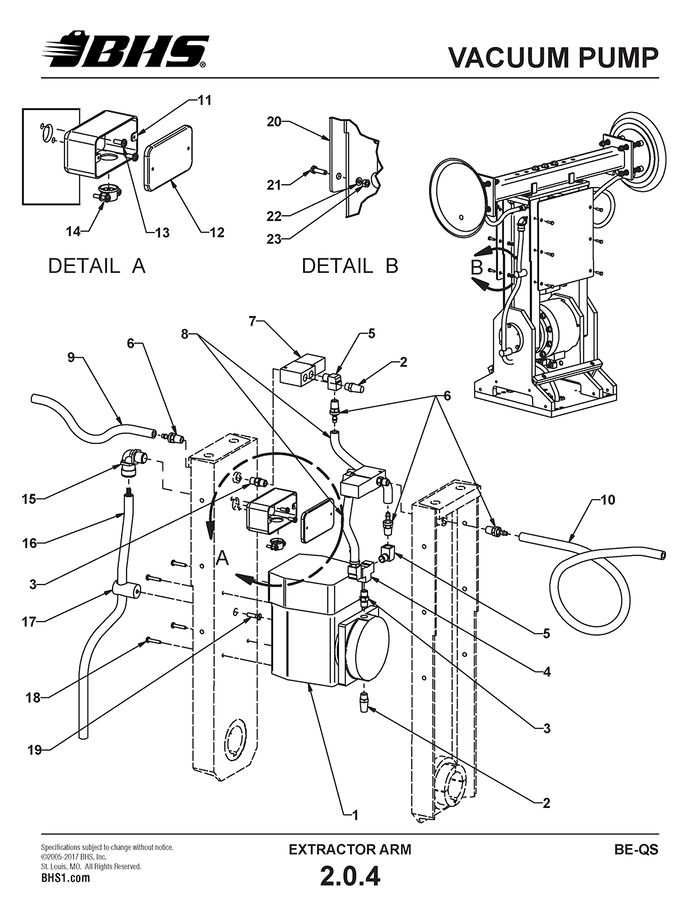
VACUUM PUMP
ITEM | BHS PART NUMBER | DESCRIPTION | REF. KIT NO. | NOTES | NO. REQ |
1 | P0005 | PUMP-VACUUM | 1 | ||
2 | P0208 | FILTER-HI FLOW | 3 | ||
3 | P0503 | NIPPLE-#4 NPT-BRASS | 3 | ||
4 | P0502 | TEE-#4 FNPT-BRASS | 1 | ||
5 | P0506 | ELBOW-STR-90 DEG-#4 NPT-BRASS | 4 | ||
6 | P0402 | HOSE BARB-1/4" X #4 MNPT-BRASS | 6 | ||
7 | P0207 | VALVE-VACUUM RELEASE | 2 | ||
8 | P0302 | HOSE-VACUUM-1/4" ID | TWO 6" PIECES | 1 FT | |
9 | P0302 | HOSE-VACUUM-1/4" ID | SHORT ARM SIDE | 1 FT | |
10 | P0302 | HOSE-VACUUM-1/4" ID | LONG ARM SIDE | 2 FT | |
11 | E0611 | JUNCTION BOX-4" X 2" X 2" | 1 | ||
12 | E0612 | COVER-JUNCTION BOX | 1 | ||
13 | HW0212 | SCREW-RHMS-#10-24 X 1/2" | 2 | ||
14 | E0624 | CONNECTOR-1/2" | 1 | ||
15 | E0608-1 | RESTRAINT-1/2"-90 DEG | GRIP SIZE .450 - .560 | 1 | |
E0617 | LOCKNUT-CONDUIT-1/2" | NOT SHOWN | 2 | ||
16 | E0514 | CORD-16-5 SW/SOW | 15 FT | ||
17 | 43057014 | STANDOFF-CABLE | 1 | ||
18 | HW0206 | SCREW-RHMS-#10-32 X 3/4" | 4 | ||
19 | HW0306 | BOLT-FHSCS-1/4-20 X 1" | 1 | ||
20 | 43057021 | PLATE-STIFFENER | † | 2 | |
21 | HW0402 | BOLT-HHCS-3/8-16 X 1" | † | 12 | |
22 | HW0107 | WASHER-LOCK-3/8" | † | 12 | |
23 | HW0005 | NUT-HEX-3/8-16 | † | 12 | |
24 | HW0108 | WASHER-FLAT-3/8"-SAE | † | NOT SHOWN | 24 |
25 | P0111 | FILTER-VACUUM-INLINE | NOT SHOWN | 2 |
† INCLUDED IN MULTIPLE KITS
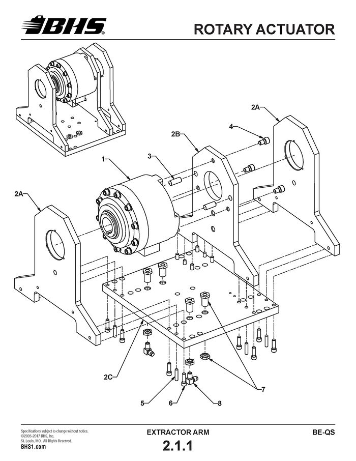
ROTARY ACTUATOR
ITEM | BHS PART NUMBER | DESCRIPTION | REF. KIT NO. | NOTES | NO. REQ |
1 | 43046001 | ROTARY ACTUATOR | 1 | ||
2 | 80000002 | ROTARY ACTUATOR BASE ASSEMBLY | WITHOUT ACTUATOR | 1 | |
2A | N/A | VERTICAL CARRIER PLATE-OUTER | INCL. WITH 80000002 | 2 | |
2B | N/A | VERTICAL CARRIER PLATE-INNER | INCL. WITH 80000002 | 1 | |
2C | N/A | CARRIER BASE PLATE | INCL. WITH 80000002 | 1 | |
3 | HW1070 | PIN-PULL DOWEL-5/8" X 1 1/2" | 2 | ||
4 | HW0508 | BOLT-SHCS-1/2-13 X 3/4" | 3 | ||
5 | HW1045 | PIN-PULL DOWEL-3/8" X 1 1/2" | INCL. WITH 80000002 | 6 | |
6 | HW0412 | BOLT-SHCS-3/8-16 X 1 1/4" | INCL. WITH 80000002 | 12 | |
7 | H0010 | FITTING-BULKHEAD-3/4-16 X #4 FNPT | 4 | ||
8 | H1579 | ADAPTER-90 DEG-#6 JICM X #4 MNPT | 2 |
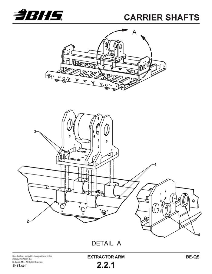
CARRIER SHAFTS
ITEM | BHS PART NUMBER | DESCRIPTION | REF. KIT NO. | NOTES | NO. REQ |
1 | 43057013 | CARRIER SHAFT-EXTRACTOR ARM | 2 | ||
2 | 43054007 | BEARING-EXTRACTOR ARM CARRIER | 80252002 | 4 | |
3 | HW0412 | BOLT-SHCS-3/8-16 X 1 1/4" | 80252002 | 16 | |
4 | PT0413 | COLLAR-SHAFT-3" | 4 | ||
5 | PT0624 | FITTING-ZERK | 80252002 | NOT SHOWN | 4 |
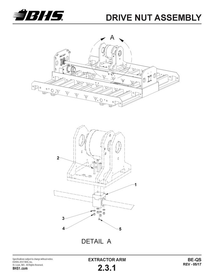
DRIVE NUT ASSEMBLY
ITEM | BHS PART NUMBER | DESCRIPTION | REF. KIT NO. | NOTES | NO. REQ |
1 | 43054006 | DRIVE NUT ASSEMBLY | 80252003 | 1 | |
2 | HW0426 | BOLT-SHCS-3/8-16 X 5 1/2" | 80252003 | † SEE NOTES | 4 |
3 | HW0108 | WASHER-FLAT-3/8"-SAE | 80252003 | † SEE NOTES | 4 |
4 | HW0006 | NUT-NILN-3/8-16 | 80252003 | † SEE NOTES | 4 |
5 | PT0624 | FITTING-ZERK | 80252003 | 1 |
† IT IS RECOMMENDED TO REPLACE MOUNTING HARDWARE WHEN REPLACING DRIVE NUT ASSEMBLY
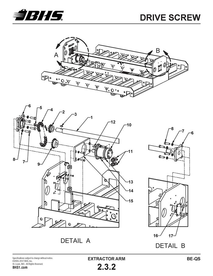
DRIVE SCREW
ITEM | BHS PART NUMBER | DESCRIPTION | REF. KIT NO. | NOTES | NO. REQ |
1 | 43024001 | SCREW-LINEAR DRIVE | 1 | ||
2 | PT0119 | SPROCKET-50B15 X 1 3/16" | 1 | ||
3 | 43097004 | KEY-1/4" X 7/8" | 1 | ||
4 | 00158001-15 | CHAIN-ROLLER-#50 | 1 | ||
5 | PT0102 | LINK-CONNECTING-#50 | 1 | ||
6 | PT0406 | FLANGE BEARING-4 BOLT-1 3/16" | ALLOY CASTING | 2 | |
7 | HW0503 | BOLT-HHCS-1/2-13 X 1 1/2" | 8 | ||
8 | HW0110 | WASHER-LOCK-1/2" | 8 | ||
9 | PT0107 | SPROCKET-50B15 X 1" | 1 | ||
10 | HC0121 | MOTOR-HYDRAULIC-100CC | SAE 2-BOLT MOUNT | 1 | |
11 | H1605 | ADAPTER-90 DEG-#6 JICM X #10 SAEM | 2 | ||
12 | HW1071 | KEY-WOODRUFF-#808 STD | SUPPLIED WITH ITEM 10 | A/R | |
13 | HW0403 | BOLT-HHCS-3/8-16 X 1 1/4" | 6 | ||
14 | HW0107 | WASHER-LOCK-3/8" | 6 | ||
15 | 43017007 | PLATE-MOUNTING-SCREW DRIVE MOTOR | 1 | ||
16 | 43057019 | PLATE-COVER | 2 | ||
17 | HW0415 | BOLT-SHCS-3/8-16 X 3/4" | 8 |
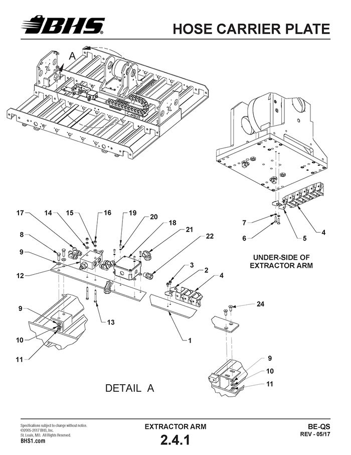
HOSE CARRIER PLATE
ITEM | BHS PART NUMBER | DESCRIPTION | REF. KIT NO. | NOTES | NO. REQ |
1 | 43915018 | PLATE-HOSE CARRIER | 1 | ||
2 | PT0618 | BRACKET-FIXED END | 1 | ||
3 | HW0301 | BOLT-SELF TAP "F"-1/4-20 X 1/2" | 2 | ||
4 | PT0617 | HOSE CARRIER | 20 LINKS REQ’D. | 3 FT | |
5 | PT0619 | BRACKET-MOVING END | 1 | ||
6 | HW0303 | BOLT-HHCS-1/4-20 X 1" | 2 | ||
7 | HW0103 | WASHER-LOCK-1/4" | 2 | ||
8 | HW0403 | BOLT-HHCS-3/8-16 X 1 1/4" | † SEE NOTES | 2 | |
9 | HW0108 | WASHER-FLAT-3/8"-SAE | 6 | ||
10 | HW0107 | WASHER-LOCK-3/8" | 4 | ||
11 | HW0005 | NUT-HEX-3/8-16 | 4 | ||
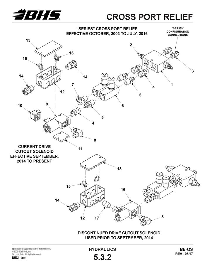
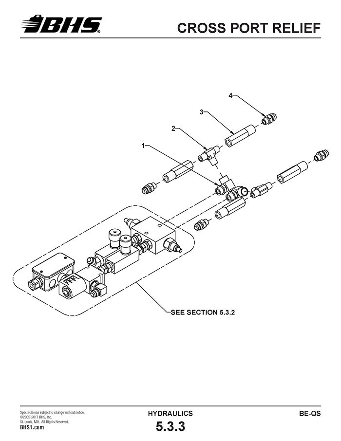
12 | HC0262 | VALVE-CROSS PORT RELIEF | INCL. CARTRIDGES | 1 | |
12a | 43846002 | REPLACEMENT CARTRIDGE | †† FOR ITEM 12 (NOT SHOWN) | 2 | |
13 | HW0308 | BOLT-HHCS-1/4-20 X 2 1/2" | 2 | ||
14 | HW0104 | WASHER-FLAT-1/4"-SAE | 2 | ||
15 | HW0103 | WASHER-LOCK-1/4" | 2 | ||
16 | HW0002 | NUT-HEX-1/4-20 | 2 | ||
17 | H1560 | ADAPTER-45 DEG-#8 JICM X #8 SAEM | 4 | ||
18 | E1329 | JUNCTION BOX-4" X 4" X 2" | PVC - INCL. COVER | 1 | |
19 | HW0212 | SCREW-RHMS-#10-24 X 1/2" | 4 | ||
20 | HW0102 | WASHER-FLAT-#10-SAE | 4 | ||
21 | E0623 | RESTRAINT-1/2"-90 DEG | GRIP SIZE .250 TO .375 | 2 | |
22 | E0622 | RESTRAINT-1/2" | GRIP SIZE .450 TO .560 | 1 | |
23 | E0617 | LOCKNUT-CONDUIT-1/2" | FOR 21 & 22 (NOT SHOWN) | 3 | |
24 | HW1076 | BOLT-FHSCS-3/8-16 X 1" | † SEE NOTES | 2 |
† UNITS BUILT PRIOR TO FEBRUARY, 2014 WITHOUT EXTENDED REACH OPTION USE (4) HW0403 MOUNTING BOLTS.
†† CARTRIDGES ARE FOR REPLACEMENT ONLY
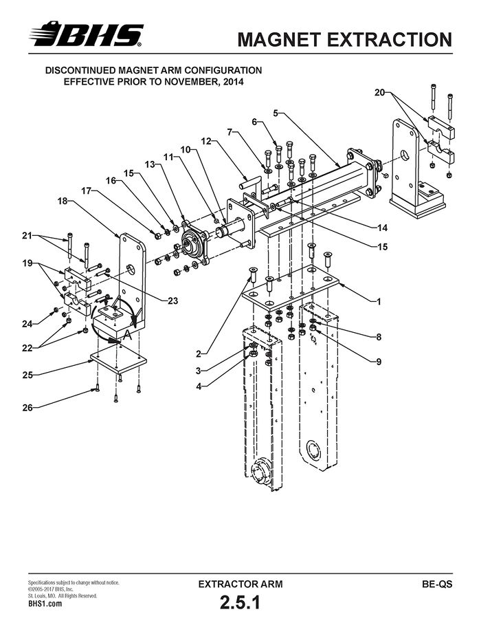
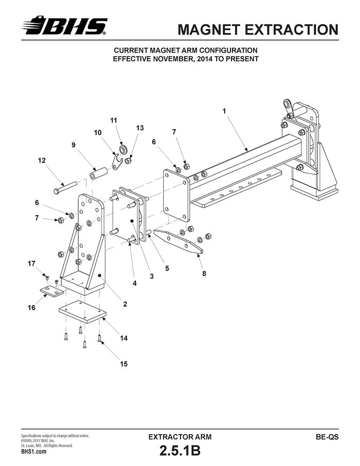
MAGNET EXTRACTION
ITEM | BHS PART NUMBER | DESCRIPTION | REF. KIT NO. | NOTES | NO. REQ |
1 | 41257014 | TIE PLATE-SWING ARM | ALL UNITS | 1 | |
- | 41655008 | EXTENSION-ARM | BE-36 ONLY (NOT SHOWN) | 1 | |
- | 43455001 | EXTENSION-ARM | BE-42 ONLY (NOT SHOWN) | ||
2 | HW0603 | BOLT-FHSCS-5/8-11 X 2" | 4 | ||
3 | HW0113 | WASHER-LOCK-5/8" | 4 | ||
4 | HW0010 | NUT-JAM-5/8-11 | 4 | ||
5 | 41655001 | CARRIER TUBE-MAGNET SWING SHAFT | 1 | ||
6 | HW0504 | BOLT-HHCS-1/2-13 X 2" | 6 | ||
7 | HW0112 | WASHER-FLAT-1/2"-SAE | 6 | ||
8 | HW0110 | WASHER-LOCK-1/2" | 6 | ||
9 | HW0007 | NUT-HEX-1/2-13 | 6 | ||
10 | 41657006 | SHAFT-MAGNET SWING | 1 | ||
11 | 41698001 | KEY-3/8" X 7/16" | 2 | ||
12 | N/A | STOP-MAGNET SWING | † DISCONTINUED | 1 | |
13 | PT0430 | FLANGE BEARING-4 BOLT-1 1/2" | 2 | ||
14 | HW0513 | BOLT-HHCS-1/2-13 X 2 1/4" | 8 | ||
15 | HW0112 | WASHER-FLAT-1/2"-SAE | 16 | ||
16 | HW0110 | WASHER-LOCK-1/2" | 8 | ||
17 | HW0007 | NUT-HEX-1/2-13 | 8 | ||
18 | 41655002 | PLATE-MAGNET MOUNTING | 2 | ||
19 | 41257015 | BLOCK-TIGHTENER | 2-PIECE ITEM | 1 | |
20 | 41257016 | BLOCK-FIXED | 2-PIECE ITEM | 1 | |
21 | HW0423 | BOLT-SHCS-3/8-16 X 3 1/2" | 4 | ||
22 | HW0006 | NUT-NILN-3/8-16 | 4 | ||
23 | HW0806 | SET SCREW-3/8-16 X 2" | REPLACES SWIVEL HEAD | 4 | |
24 | HW0424 | NUT-JAM-3/8-16 | 4 | ||
25 | 41657017 | INSULATOR-MAGNET MOUNT | 2 | ||
26 | HW0306 | BOLT-FHSCS-1/4-20 X 1" | 8 | ||
27 | 41657008 | PAD-MAGNET SLIDE | 2 | ||
28 | HW0314 | BOLT-FHSCS-1/4-20 X 1/2" | 4 |
† REFER TO SECTION 2.5.1A FOR REPLACEMENT / UPGRADE PARTS
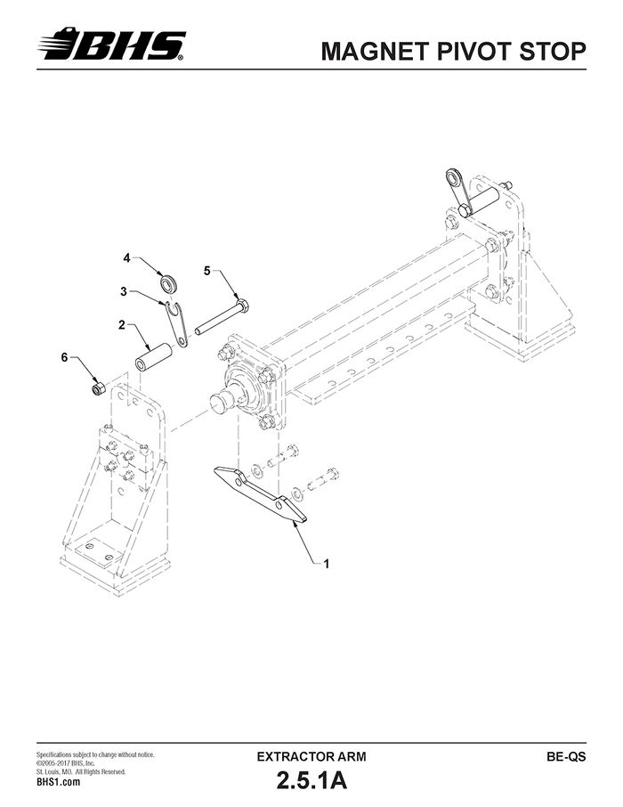
MAGNET PIVOT STOP
ITEM | BHS PART NUMBER | DESCRIPTION | REF. KIT NO. | NOTES | NO. REQ |
REF | 80252012 | MAGNET SWING STOP KIT | INCL. ITEMS 1 THRU 6 | A/R | |
1 | 43057029 | PLATE-STOP | 1 | ||
2 | 43058003 | SLEEVE-STOP | 2 | ||
3 | 43057030 | SUPPORT-CABLE | 2 | ||
4 | PL0501 | GROMMET-1/2" | 2 | ||
5 | HW0509 | BOLT-HHCS-1/2-13 X 4 1/2" | 2 | ||
6 | HW0008 | NUT-NILN-1/2-13 | 2 |
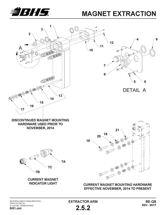
MAGNET EXTRACTION
ITEM | BHS PART NUMBER | DESCRIPTION | REF. KIT NO. | NOTES | NO. REQ |
REF | 43052007 | MAGNET PUSH/PULL ARM ASSEMBLY | INCL. ITEMS 1 THRU 17 | 1 | |
1 | 43055009 | MAGNET PUSH/PULL ARM | 1 | ||
2 | 43055010 | MAGNET MOUNT | 2 | ||
3 | PT0470 | BEARING-MAGNET PIVOT | 2 | ||
4 | HW0525 | BOLT-CARRIAGE-1/2-13 X 1 1/2" | 12 | ||
5 | HW0524 | BOLT-CARRIAGE-1/2-13 X 2" | STOP PLATE LOCATION | 4 | |
6 | HW0110 | WASHER-LOCK-1/2" | 16 | ||
7 | HW0007 | NUT-HEX-1/2-13 | 16 | ||
8 | 43058009 | PLATE-ROTATION STOP | 2 | ||
9 | 43058003 | SLEEVE-STOP | 2 | ||
10 | 43058010 | SUPPORT-CABLE | 2 | ||
11 | PL0501 | GROMMET-1/2" | 2 | ||
12 | HW0523 | BOLT-HHCS-1/2-13 X 4" | 2 | ||
13 | HW0008 | NUT-NILN-1/2-13 | 2 | ||
14 | 43057037 | INSULATOR-BOTTOM | 2 | ||
15 | HW0306 | BOLT-FHSCS-1/4-20 X 1" | 8 | ||
16 | 41657008 | SLIDE-MAGNET | 2 | ||
17 | HW0314 | BOLT-FHSCS-1/4-20 X 1/2" | 4 |
ITEM | BHS PART NUMBER | DESCRIPTION | REF. KIT NO. | NOTES | NO. REQ |
REF | 43032009 | MAGNET ASSEMBLY | INCLUDES ITEMS 1 THRU 12 | A/R | |
1 | N/A | ELECTROMAGNET-95VDC | 2 | ||
2 | E0314 | SENSOR-PROXIMITY-30MM | 2 | ||
3 | N/A | GASKET-REAR | DISCONTINUED - NOT USED | 2 | |
4 | 41657002 | COVER-PROXIMITY SENSOR HOUSING | REAR | 2 | |
5 | HW1065 | SCREW-SHCS-#6-32 X 3/8" | 8 | ||
6 | HW1066 | WASHER-LOCK-#6 | 8 | ||
7 | N/A | INDICATOR LIGHT | SEE PART #’S BELOW | 2 | |
8 | E0335 | RECEPTACLE-5 PIN MALE | WITH 12" LEAD | 2 | |
9 | E0617 | LOCKNUT-CONDUIT-1/2" | 2 | ||
10 | N/A | GASKET-FRONT | DISCONTINUED - NOT USED | 2 | |
11 | 41657003 | COVER-PROXIMITY SENSOR HOUSING | 80252015 | FRONT | 2 |
12 | HW0138 | SCREW-FHSCS-#8-32 X 3/8" | 80252015 | 8 | |
13 | HW0433 | STUD-1/2-13 X 5" | 80252006 | FOR UNITS WITH MAGNET PIVOT SHAFT ONLY. SEE SECTION 2.5.1 (UNITS BUILT PRIOR TO 11/01/14) | 8 |
14 | HW0007 | NUT-HEX-1/2-13 | 80252006 | 8 | |
15 | HW0112 | WASHER-FLAT-1/2"-SAE | 80252006 | 40 | |
16 | HW1002 | SPRING-1/2" | 80252006 | 24 | |
17 | HW0008 | NUT-NILN-1/2-13 | 80252006 | 8 | |
18 | HW0514 | BOLT-HHCS-1/2-13 X 2 1/2" | 80252014 | FOR UNITS WITH INDEPENDENT PIVOT BEARINGS ONLY. SEE SECTION 2.5.1B (UNITS BUILT 11/01/14 TO PRESENT) | 4 |
19 | HW1002 | SPRING-1/2" | 80252014 | 4 | |
20 | HW0112 | WASHER-FLAT-1/2"-SAE | 80252014 | 8 | |
21 | HW0007 | NUT-HEX-1/2-13 | 80252014 | 4 | |
FOR EXTRACTORS (OR REPLACEMENT MAGNETS) SHIPPED PRIOR TO FEB, 2014 | |||||
7 | E0337 | LIGHT-PILOT-RED-120 VAC/DC | INCL. LENS AND BULB | 2 | |
- | 2EJ79 | LAMP-REPLACEMENT-INCANDESCENT | 120 VAC | A/R | |
FOR EXTRACTORS (OR REPLACEMENT MAGNETS) SHIPPED FROM FEB, 2014 TO PRESENT | |||||
7A | E0370 | HOUSING-INDICATOR LIGHT | LENS AND LAMP NOT INCL. | A/R | |
7B | E0371-A | LENS-FLUTED-AMBER | A/R | ||
7C | E0372-120 | LAMP-LED | 120 VAC | A/R | |
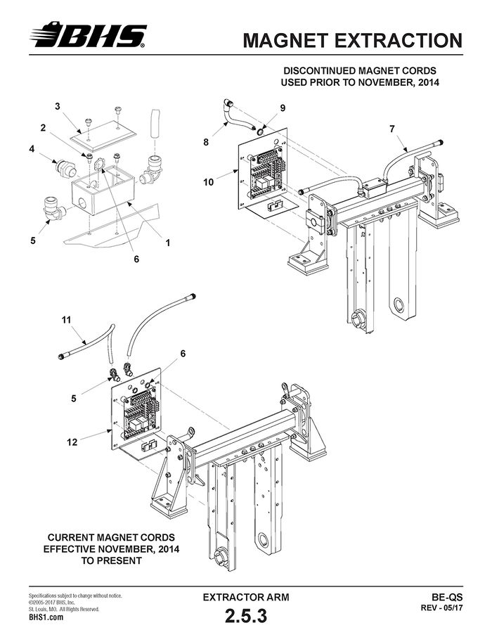
ITEM | BHS PART NUMBER | DESCRIPTION | REF. KIT NO. | NOTES | NO. REQ |
1 | E1105 | JUNCTION BOX-4" X 2" X 2" | WEATHER PROOF BOX | 1 | |
2 | HW0301 | BOLT-SELF TAP "F"-1/4-20 X 1/2" | 2 | ||
3 | E1106 | COVER-JUNCTION BOX | WEATHER PROOF W/ GASKET | 1 | |
4 | E0333 | RECEPTACLE-9 PIN MALE | WITH 12" LEAD | 1 | |
5 | E0608-1 | RESTRAINT-1/2"-90 DEG | GRIP SIZE .450 TO .560 | 2 | |
6 | E0617 | LOCKNUT-CONDUIT-1/2" | 3 | ||
7 | E0334 | CORD-5 PIN FEMALE | WITH 36" LEAD | 2 | |
8 | E0332 | CORD-9 PIN FEMALE-90 DEG | WITH 36" LEAD | 1 | |
9 | PL0501 | GROMMET-1/2" | 1 | ||
10 | 41657013-2 | PLATE-PANEL MOUNTING | W/ SINGLE CABLE HOLE | 1 | |
11 | E0334-6 | CORD-5 PIN FEMALE | WITH 72" LEAD | 2 | |
12 | 43057038-2 | PLATE-PANEL MOUNTING | W/ DUAL CABLE HOLES | 1 |
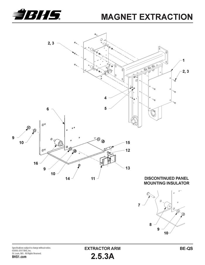
ITEM | BHS PART NUMBER | DESCRIPTION | REF. KIT NO. | NOTES | NO. REQ |
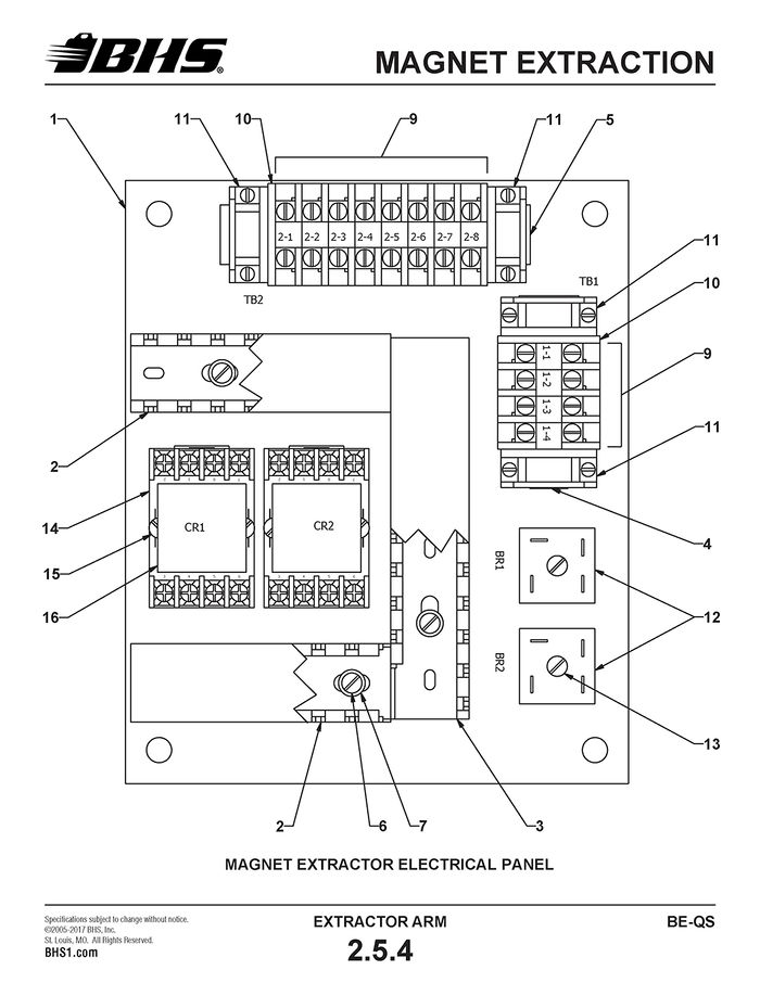
1 | 43057021 | PLATE-STIFFENER | 1 | ||
2 | HW0402 | BOLT-HHCS-3/8-16 X 1" | 12 | ||
3 | HW0108 | WASHER-FLAT-3/8"-SAE | (NOT SHOWN) | 24 | |
4 | HW0107 | WASHER-LOCK-3/8" | 12 | ||
5 | HW0005 | NUT-HEX-3/8-16 | 12 | ||
6 | 41637001 | PANEL-COMPONENT MOUNTING | 1 | ||
7 | HW0325 | BOLT-5/16-18 X 1 3/4"-PAN HEAD | 4 | ||
8 | N/A | INSULATOR-THREADED FEMALE | DISCONTINUED | 4 | |
9 | HW0106 | WASHER-FLAT-5/16"-SAE | 8 | ||
10 | HW0326 | NUT-NILN-5/16-18 | 8 | ||
11 | E1016 | FUSE HOLDER | 1 | ||
12 | HW0130 | SCREW-RHMS-#8-32 X 1/2" | 1 | ||
13 | HW0133 | WASHER-FLAT-#8-SAE | 1 | ||
14 | HW0132 | NUT-NILN-#8-32 | 1 | ||
15 | E0325 | FUSE-7AMP-250VAC | FLM-7 OR FNM-7 | 1 | |
16 | PL0307 | INSULATOR-MALE STUD | 4 |
ITEM | BHS PART NUMBER | DESCRIPTION | REF. KIT NO. | NOTES | NO. REQ |
1 | 41637001 | PANEL-COMPONENT MOUNTING | 1 | ||
2 | 41637002 | WIRE WAY | 2 | ||
3 | 41637003 | WIRE WAY | 1 | ||
4 | 41637004 | TRACK-TERMINAL BLOCK MOUNTING | 1 | ||
5 | 41637005 | TRACK-TERMINAL BLOCK MOUNTING | 1 | ||
6 | HW0130 | SCREW-RHMS-#8-32 X 1/2" | 10 | ||
7 | HW0132 | WASHER-FLAT-#8-SAE | 10 | ||
8 | HW0133 | NUT-NILN-#8-32 | NOT SHOWN | 16 | |
9 | E1020 | TERMINAL BLOCK | 12 | ||
10 | E1040 | END BARRIER | 2 | ||
11 | E1330 | END ANCHOR | 4 | ||
12 | E1009 | RECTIFIER-FULL WAVE BRIDGE | 2 | ||
13 | HW0135 | SCREW-RHMS-#8-32 X 3/4" | 2 | ||
14 | E1313 | SOCKET-RELAY-8 PIN | 2 | ||
15 | HW0139 | SCREW-RHMS-#8-32 X 1 1/4" | 4 | ||
16 | E0331 | RELAY-DPDT-110VAC | WITH INDICATOR LIGHT | 2 |
ITEM | BHS PART NUMBER | DESCRIPTION | REF. KIT NO. | NOTES | NO. REQ |
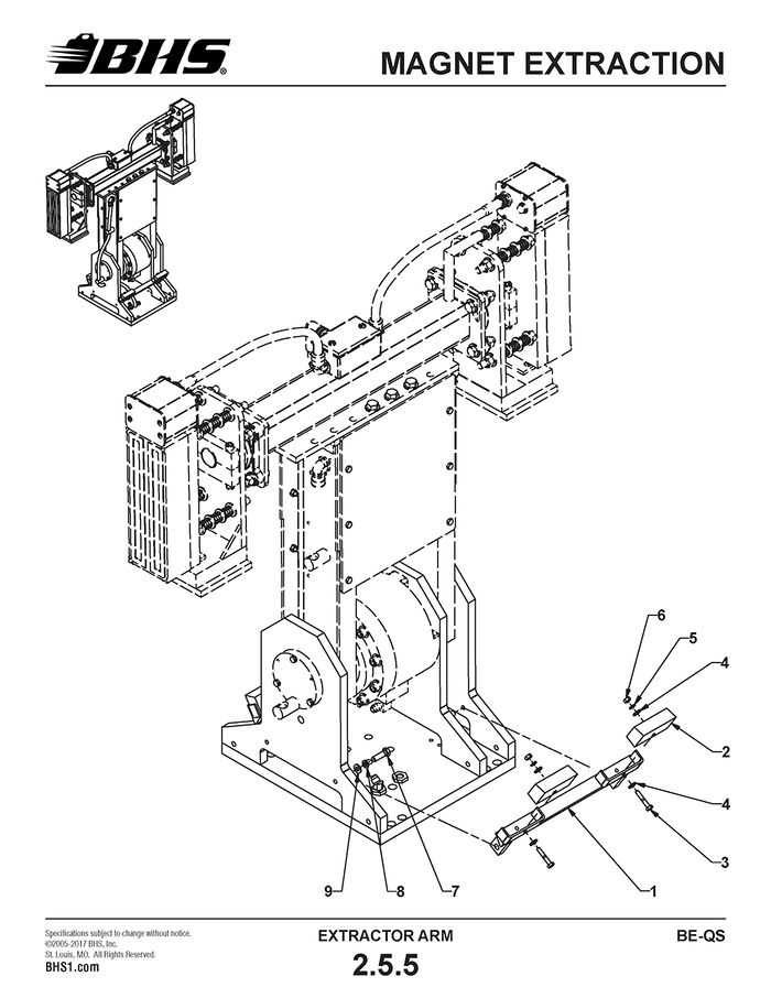
1 | 43055007 | MOUNT-STOP-SWING ARM | 2 | ||
2 | 43057024 | STOP-SWING ARM | BE-24-QS | 4 | |
43057023 | STOP-SWING ARM | BE-36 & 42-QS | 4 | ||
3 | HW0304 | BOLT-HHCS-1/4-20 X 1 1/2" | 4 | ||
4 | HW0104 | WASHER-FLAT-1/4"-SAE | 8 | ||
5 | HW0103 | WASHER-LOCK-1/4" | 4 | ||
6 | HW0002 | NUT-HEX-1/4-20 | 4 | ||
7 | HW0403 | BOLT-HHCS-3/8-16 X 1 1/4" | 4 | ||
8 | HW0107 | WASHER-LOCK-3/8" | 4 | ||
9 | HW0108 | WASHER-FLAT-3/8"-SAE | 4 |
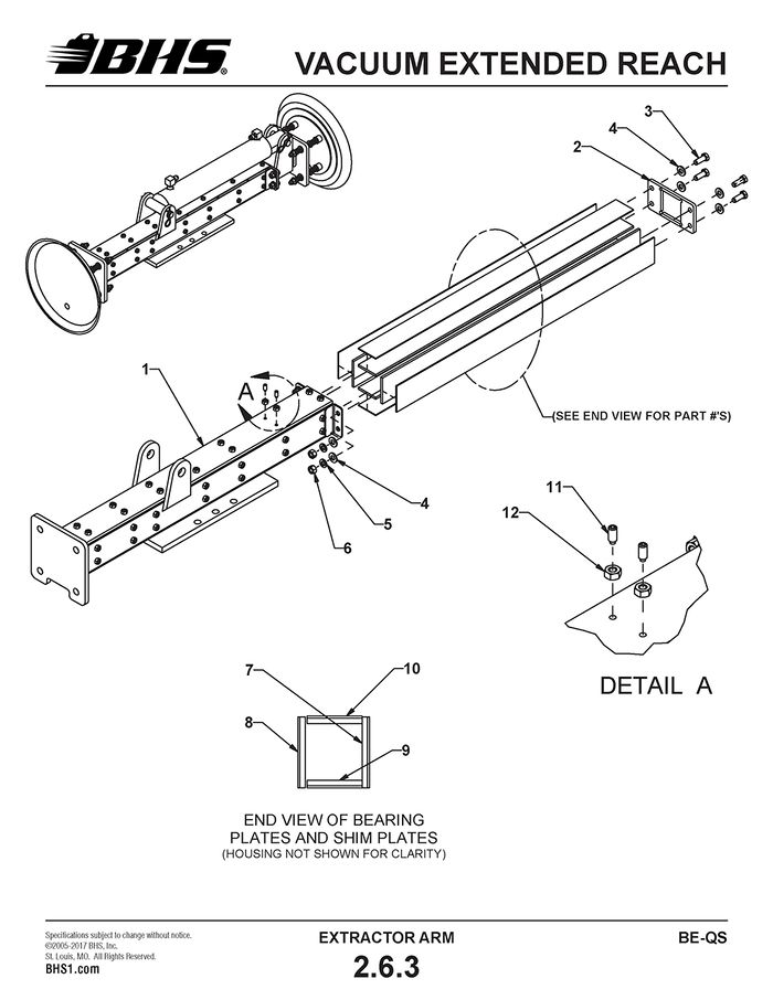
VACUUM EXTENDED REACH
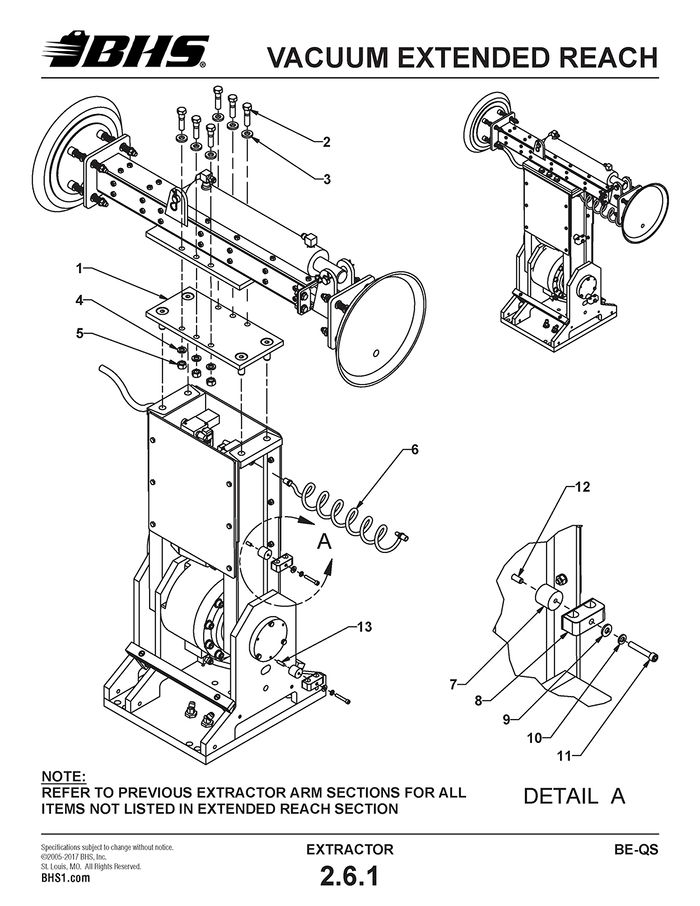
ITEM | BHS PART NUMBER | DESCRIPTION | REF. KIT NO. | NOTES | NO. REQ |
1 | 41257014 | TIE PLATE-SWING ARM | ALL UNITS | 1 | |
- | 41655008 | EXTENSION-ARM | BE-36 ONLY (NOT SHOWN) | A/R | |
- | 43455001 | EXTENSION-ARM | BE-42 ONLY (NOT SHOWN) | A/R | |
2 | HW0504 | BOLT-HHCS-1/2-13 X 2" | 6 | ||
3 | HW0112 | WASHER-FLAT-1/2"-SAE | 6 | ||
4 | HW0110 | WASHER-LOCK-1/2" | 6 | ||
5 | HW0007 | NUT-HEX-1/2-13 | 6 | ||
6 | P0301-1 | HOSE-COIL-VACUUM | 1 | ||
7 | 41257035 | STANDOFF | 2 | ||
8 | HW1072 | RESTRAINT-HOSE | 2 | ||
9 | HW0104 | WASHER-FLAT-1/4"-SAE | 2 | ||
10 | HW0103 | WASHER-LOCK-1/4" | 2 | ||
11 | HW0318 | BOLT-SHCS-1/4-20 X 1 1/2" | 2 | ||
12 | HW0302 | BOLT-HHCS-1/4-20 X 3/4" | 1 | ||
13 | HW0312 | SCREW-SHSS-1/4-20 X 1"-CUP POINT | 1 |
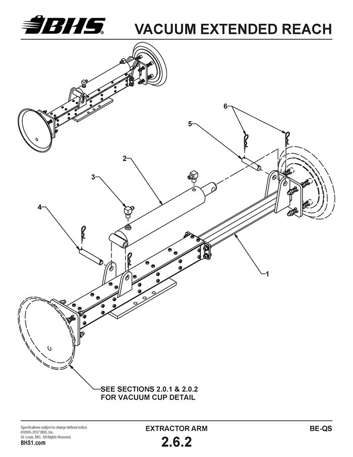
ITEM | BHS PART NUMBER | DESCRIPTION | REF. KIT NO. | NOTES | NO. REQ |
1 | 41255005 | ARM-EXTENSION-VACUUM | 1 | ||
2 | HC0416 | CYLINDER-EXTENDED REACH-VACUUM | 2 1/2" X 12" CYLINDER | 1 | |
3 | H1578 | ADAPTER-90 DEG-#6 JICM X #6 MNPT | 2 | ||
4 | 41257031 | PIN-CLEVIS END | 1 | ||
5 | 00197036 | PIN-ROD END | 1 | ||
6 | HW1058 | PIN-HITCH | 4 |
ITEM | BHS PART NUMBER | DESCRIPTION | REF. KIT NO. | NOTES | NO. REQ |
1 | 41255004 | HOUSING-EXTENDED REACH-VACUUM | 1 | ||
2 | 41257030 | PLATE-END | 1 | ||
3 | HW0402 | BOLT-HHCS-3/8-16 X 1" | 4 | ||
4 | HW0108 | WASHER-FLAT-3/8"-SAE | 8 | ||
5 | HW0107 | WASHER-LOCK-3/8" | 4 | ||
6 | HW0005 | NUT-HEX-3/8-16 | 4 | ||
7 | 41258002 | PLATE-BEARING | SIDE | 2 | |
8 | 41258005 | PLATE-SHIM | SIDE | 2 | |
9 | 41258003 | PLATE-BEARING | UPPER/ LOWER | 2 | |
10 | 41258004 | PLATE-SHIM | UPPER/ LOWER | 2 | |
11 | HW0812 | SCREW-SHSS-1/4-20 X 5/8"-HALF DOG | 28 | ||
12 | HW0002 | NUT-HEX-1/4-20 | 28 |
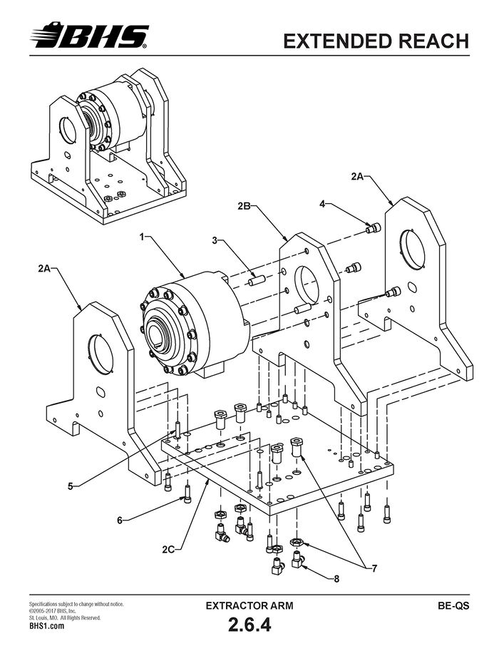
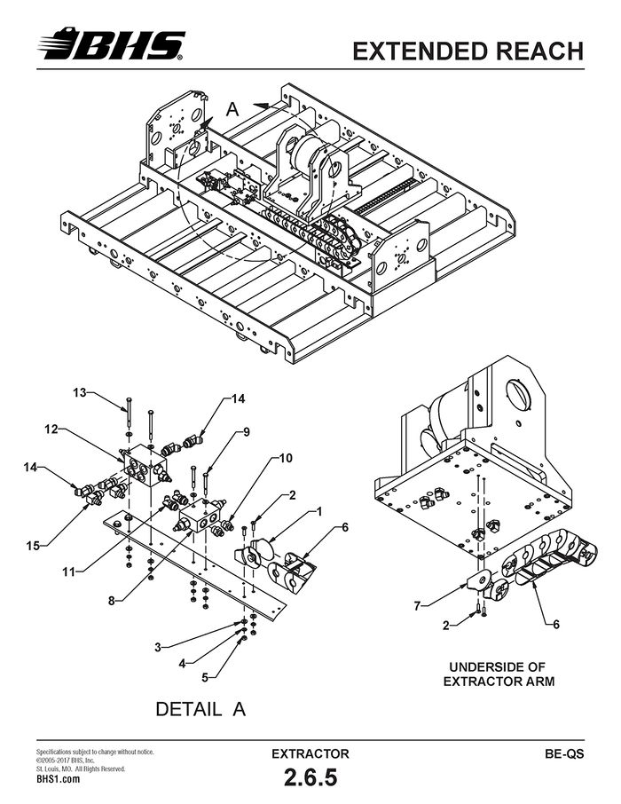
EXTENDED REACH
ITEM | BHS PART NUMBER | DESCRIPTION | REF. KIT NO. | NOTES | NO. REQ |
1 | 43046001 | ROTARY ACTUATOR | 1 | ||
2 | 80000002 | ROTARY ACTUATOR BASE ASSEMBLY | WITHOUT ACTUATOR | 1 | |
2A | N/A | VERTICAL CARRIER PLATE-OUTER | INCL. WITH 80000002 | 2 | |
2B | N/A | VERTICAL CARRIER PLATE-INNER | INCL. WITH 80000002 | 1 | |
2C | N/A | CARRIER BASE PLATE | INCL. WITH 80000002 | 1 | |
3 | HW1070 | PIN-PULL DOWEL-5/8 X 1 1/2" | 2 | ||
4 | HW0508 | BOLT-SHCS-1/2-13 X 3/4" | 3 | ||
5 | HW1045 | PIN-PULL DOWEL-3/8" X 1 1/2" | INCL. WITH 80000002 | 6 | |
6 | HW0412 | BOLT-SHCS-3/8-16 X 1 1/4" | INCL. WITH 80000002 | 12 | |
7 | H0010 | FITTING-BULKHEAD-3/4-16 X #4 FNPT | 4 | ||
8 | H1579 | ADAPTER-90 DEG-#6 JICM X #4 MNPT | 4 |
ITEM | BHS PART NUMBER | DESCRIPTION | REF. KIT NO. | NOTES | NO. REQ |
1 | 41696001 | BRACKET-MOVABLE END | 1 | ||
2 | HW0306 | BOLT-FHSCS-1/4-20 X 1" | 4 | ||
3 | HW0104 | WASHER-FLAT-1/4"-SAE | 10 | ||
4 | HW0103 | WASHER-LOCK-1/4" | 6 | ||
5 | HW0002 | NUT-HEX-1/4-20 | 6 | ||
6 | PT0627 | HOSE CARRIER | 14 LINKS REQD. | 39" | |
7 | PT0628 | BRACKET-FIXED END | 1 | ||
8 | HC0261 | VALVE-CROSS PORT RELIEF | 1 | ||
8a | 43046003 | REPLACEMENT CARTRIDGE | † FOR ITEM 8 (NOT SHOWN) | 2 | |
9 | HW0308 | BOLT-HHCS-1/4-20 X 2 1/2" | 2 | ||
10 | H1546 | ADAPTER-#6 JICM X #8 SAEM | 2 | ||
11 | H1617 | ADAPTER-45 DEG-#6 JICM X #8 SAEM | 2 | ||
12 | HC0237 | VALVE-SEQUENCING | 1 | ||
12a | 43046005 | REPLACEMENT CARTRIDGE | † FOR ITEM 12 (NOT SHOWN) | A/R | |
13 | HW0317 | BOLT-HHCS-1/4-20 X 3 1/2" | 2 | ||
14 | H1560 | ADAPTER-45 DEG-#8 JICM X #8 SAEM | 4 | ||
15 | H1600 | ADAPTER-90 DEG-#6 JICM X #8 SAEM | 2 |
† CARTRIDGES ARE FOR REPLACEMENT ONLY
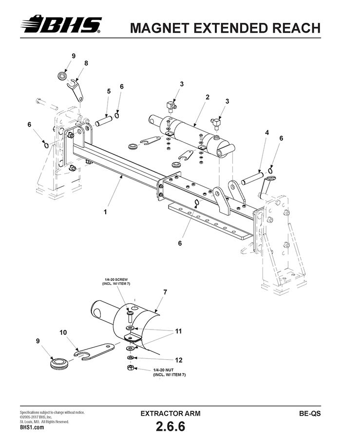
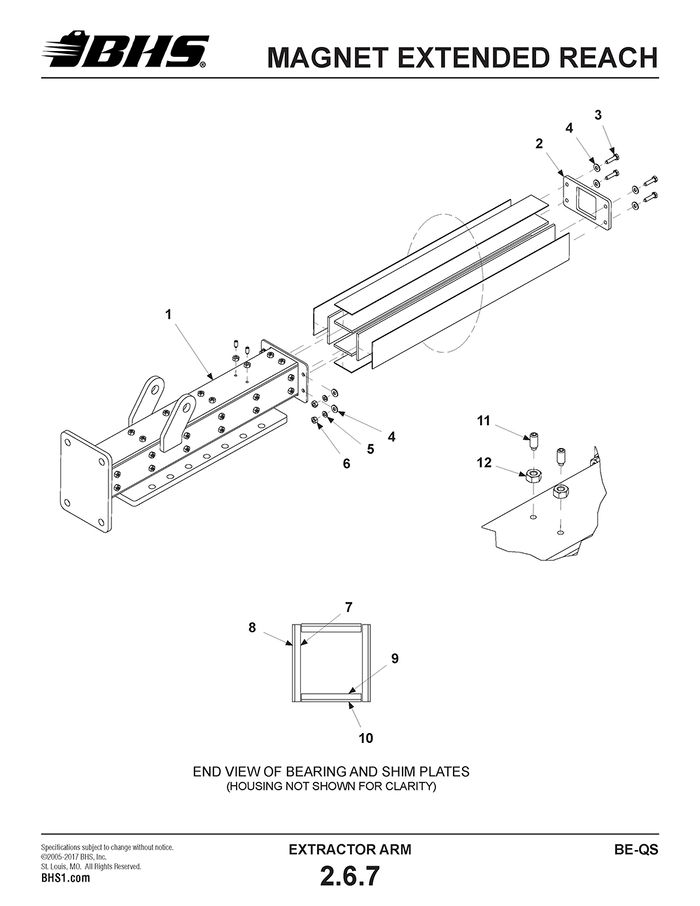
MAGNET EXTENDED REACH
ITEM | BHS PART NUMBER | DESCRIPTION | REF. KIT NO. | NOTES | NO. REQ |
1 | 43055011 | ARM-EXTENSION-MAGNET | 1 | ||
2 | HC0415 | CYLINDER-EXTENDED REACH-MAGNET | 2 1/2" X 8" CYLINDER | 1 | |
3 | H1578 | ADAPTER-90 DEG-#6 JICM X #6 MNPT | 2 | ||
4 | 43057042 | PIN-CLEVIS END | 1 | ||
5 | 43057043 | PIN-ROD END | 1 | ||
6 | HW1132 | RETAINING RING-EXTERNAL-3/4" ID | 4 | ||
7 | HW1043 | CLAMP-CYLINDER | 2 | ||
8 | 43057044-2 | SUPPORT-CABLE | 2 | ||
9 | PL0501 | GROMMET-1/2" | 4 | ||
10 | 43058019 | SUPPORT-CABLE-BAND CLAMP | 2 | ||
11 | HW0104 | WASHER-FLAT-1/4"-SAE | 4 | ||
12 | HW0103 | WASHER-LOCK-1/4" | 2 |
ITEM | BHS PART NUMBER | DESCRIPTION | REF. KIT NO. | NOTES | NO. REQ |
1 | 43055012 | HOUSING-EXTENDED REACH-MAGNET | 1 | ||
2 | 50057008 | PLATE-END | 1 | ||
3 | HW0402 | BOLT-HHCS-3/8-16 X 1" | 4 | ||
4 | HW0108 | WASHER-FLAT-3/8"-SAE | 8 | ||
5 | HW0107 | WASHER-LOCK-3/8" | 4 | ||
6 | HW0005 | NUT-HEX-3/8-16 | 4 | ||
7 | 43058013 | PLATE-BEARING-SIDE | 2 | ||
8 | 43058016 | PLATE-SHIM-SIDE | 2 | ||
9 | 43058014 | PLATE-BEARING-UPPER/LOWER | 2 | ||
10 | 43058015 | PLATE-SHIM-UPPER/LOWER | 2 | ||
11 | HW0812 | SCREW-SHSS-1/4-20 X 5/8"-HALF DOG | 24 | ||
12 | HW0002 | NUT-HEX-1/4-20 | 24 |
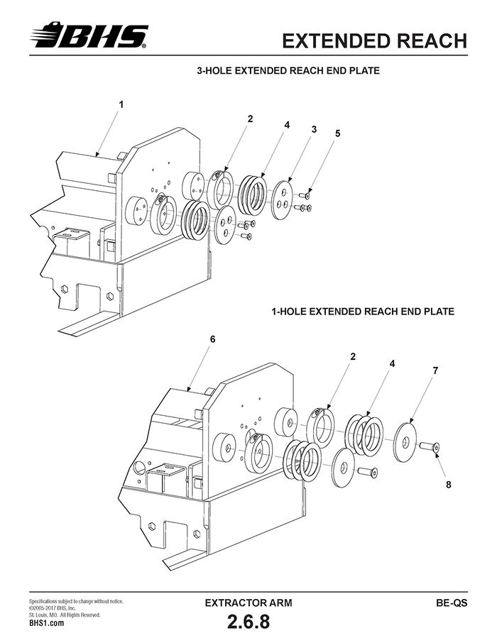
EXTENDED REACH
ITEM | BHS PART NUMBER | DESCRIPTION | REF. KIT NO. | NOTES | NO. REQ |
1 | N/A | CARRIER SHAFT-EXTRACTOR ARM | † 3-HOLE VERSION | A/R | |
2 | PT0413 | COLLAR-SHAFT-3" | 4 | ||
3 | 50057009 | PLATE-END-3 HOLE | REPLACEMENT PART ONLY | 4 | |
4 | 50057010 | SHIM-END PLATE | ††SEE NOTES | A/R | |
5 | HW1076 | BOLT-FHSCS-3/8-16 X 1" | 12 | ||
6 | 43057045 | CARRIER SHAFT-EXTRACTOR ARM | 1-HOLE VERSION | 2 | |
7 | 43017076 | PLATE-END-1 HOLE | 4 | ||
8 | HW0603 | BOLT-FHSCS-5/8-11 X 2" | 4 |
† 3-HOLE CARRIER SHAFT NO LONGER AVAILABLE. MUST REPLACE 3-HOLE SHAFT W/ CURRENT, 1-HOLE VERSION ALONG WITH NEW END PLATES & HARDWARE.
†† SHIM QUANTITY VARIES DUE TO MANUFACTURING TOLERANCES.
DRIVE AND IDLER CASTERS
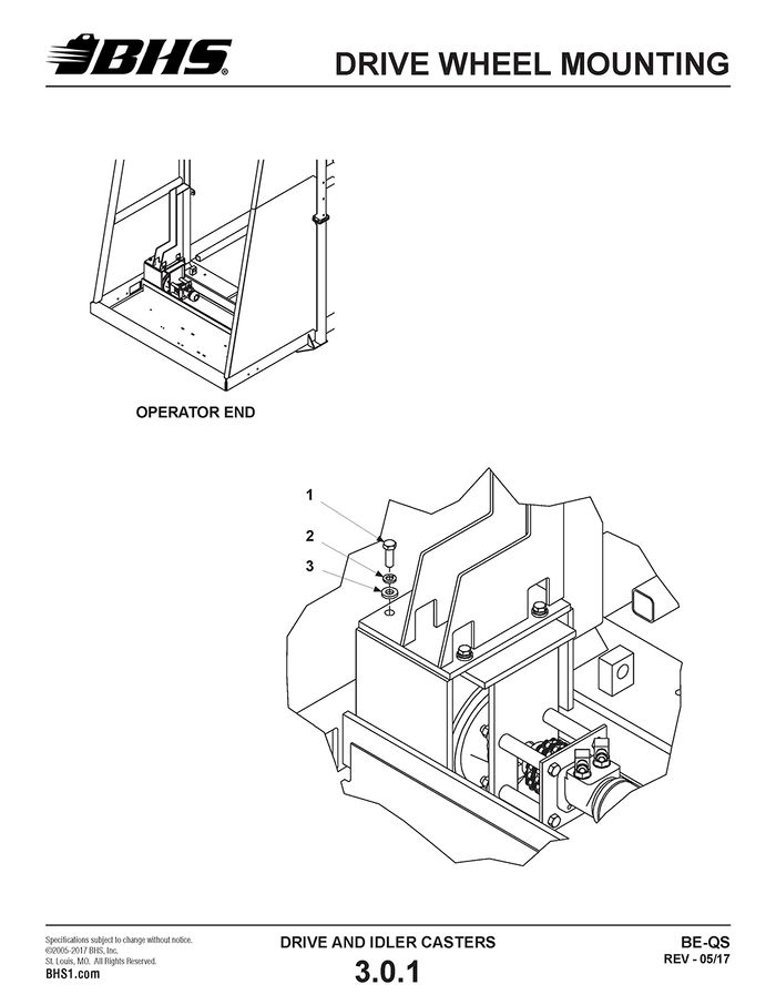
DRIVE WHEEL MOUNTING
ITEM | BHS PART NUMBER | DESCRIPTION | REF. KIT NO. | NOTES | NO. REQ |
1 | HW0503 | BOLT-HHCS-1/2-13 X 1 1/2" | 8 | ||
2 | HW0110 | WASHER-LOCK-1/2" | 8 | ||
2 | HW0112 | WASHER-FLAT-1/2"-SAE | 8 |
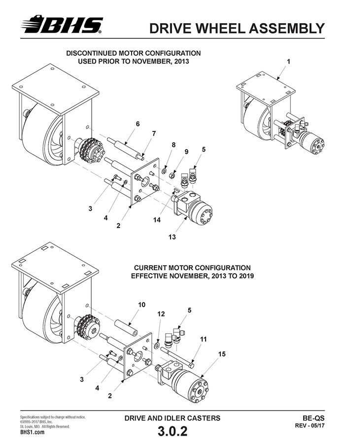
DRIVE WHEEL ASSEMBLY
ITEM | BHS PART NUMBER | DESCRIPTION | REF. KIT NO. | NOTES | NO. REQ |
1 | 43822001-6B | FLOOR DRIVE ASSEMBLY (W/ 200CC MOTOR) | † SEE NOTES | 2 | |
43822004-6B | FLOOR DRIVE ASSEMBLY (W/ 400CC MOTOR) | † SEE NOTES | 2 | ||
2 | 43827004 | PLATE-MOTOR MOUNTING | 2 | ||
3 | HW0416 | BOLT-SHCS-3/8-16 X 1" | 8 | ||
4 | HW0107 | WASHER-LOCK-3/8" | 8 | ||
5 | H1612 | ADAPTER-90 DEG-#8 JICM X #10 SAEM | 4 | ||
6 | N/A | ROD-THREADED-1/2-13 X 7 3/4" | †† SEE NOTES | 8 | |
7 | N/A | SPACER-DRIVE WHEEL-4.75" LG | †† SEE NOTES | 8 | |
8 | HW0110 | WASHER-LOCK-1/2" | 8 | ||
9 | HW0007 | NUT-HEX-1/2-13 | 8 | ||
10 | 43827006 | SPACER-DRIVE WHEEL-4.125" LG | MUST BE ORDERED AS SET OF 4 | 8 | |
11 | HW0516 | BOLT-HHCS-1/2-13 X 6 1/2" | 8 | ||
12 | HW0112 | WASHER-FLAT-1/2"-SAE | 8 | ||
13 | N/A | MOTOR-HYDRAULIC-200CC | ††† KEYED SHAFT | - | |
N/A | MOTOR-HYDRAULIC-400CC | ††† KEYED SHAFT | - | ||
14 | HW1071 | KEY-WOODRUFF-#808 STD | 2 | ||
15 | HC0124-6B | MOTOR-HYDRAULIC-200CC | † SPLINE SHAFT | 2 | |
HC0126-6B | MOTOR-HYDRAULIC-400CC | 80322003 | † SPLINE SHAFT | 2 |
† 200CC MOTORS REQUIRED FOR UNITS EQUIPPED WITH PARALLEL DRIVE CIRCUIT. 400CC MOTORS REQUIRED FOR UNITS EQUIPPED WITH SERIES DRIVE CIRCUIT. SEE SECTION 5.4 TO DETERMINE IF UNIT IS PARALLEL OR SERIES EQUIPPED AND APPROXIMATE EFFECTIVITY OF EACH TYPE.
†† PARTS OBSOLETE AND NO LONGER AVAILABLE. MUST REPLACE WITH ITEMS 10 & 11.
††† PARTS OBSOLETE AND NO LONGER AVAILABLE. MUST REPLACE WITH SPLINE DRIVE CONVERSION KIT.
NOTE: EFFECTIVITY DATES REFER TO DATES NEW EXTRACTOR UNITS ARE SHIPPED FROM THE FACTORY. REPLACEMENT PART EFFECTIVITY MAY DIFFER DUE TO FACTORY INVENTORY LEVELS AT TIME OF PARTS ORDER. CONSULT FACTORY IF UNSURE OF PARTS NEEDED.
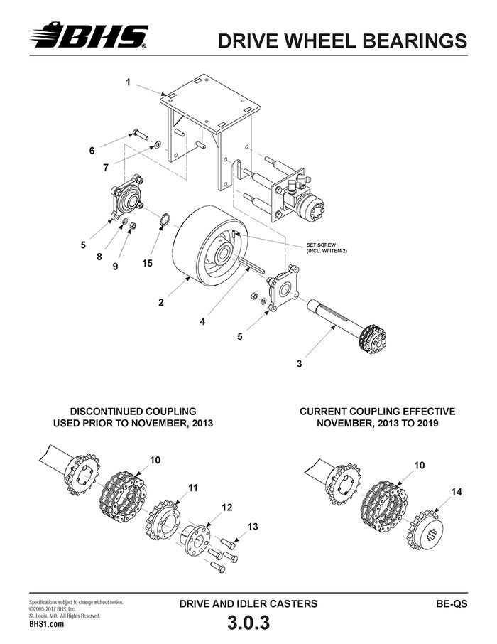
DRIVE WHEEL BEARINGS
ITEM | BHS PART NUMBER | DESCRIPTION | REF. KIT NO. | NOTES | NO. REQ |
1 | 43825001 | FRAME-FLOOR DRIVE | 2 | ||
2 | C0510-1 | WHEEL-10" X 5"-POLY | 80322001 | 2 | |
3 | 43822003 | SHAFT-WHEEL (W/ COUPLING BODY) | AVAILABLE IN MULTIPLE KITS | 2 | |
4 | 43897004 | KEY-3/8" X 4 3/4" | 80322001 | 2 | |
5 | PT0430 | FLANGE BEARING-4 BOLT-1 1/2" | 80322001 | 4 | |
6 | HW0504 | BOLT-HHCS-1/2-13 X 2" | 8 | ||
7 | HW0112 | WASHER-FLAT-1/2"-SAE | 16 | ||
8 | HW0110 | WASHER-LOCK-1/2" | 16 | ||
9 | HW0007 | NUT-HEX-1/2-13 | 16 | ||
10 | PT0321 | CHAIN-COUPLING-#50 | INCL. CONNECTING PIN | 2 | |
11 | N/A | COUPLING BODY-TAPER BORE-#50 | † SEE NOTES | 2 | |
12 | N/A | BUSHING-TAPER LOCK-1" | † SEE NOTES | 2 | |
13 | HW0323 | BOLT-HHCS-5/16-18 X 1" | 8 | ||
14 | PT0330 | COUPLING BODY-#50-SPLINE BORE | 80322003 | 2 | |
15 | HW1110 | RETAINING RING-1 1/2"-HEAVY DUTY | 80322001 | †† AVAILABLE IN MULTIPLE KITS | 2 |
† PARTS OBSOLETE AND NO LONGER AVAILABLE. SPLINE DRIVE CONVERSION KIT REQUIRED. REUSE OF BUSHINGS AFTER DISASSEMBLY NOT RECOMMENDED.
†† RETAINING RINGS USED ON UNITS SHIPPED AFTER 07/01/12. UNITS SHIPPED FROM 07/01/12 TO 11/01/13 ARE EQUIPPED WITH (2) RETAINING RINGS PER SHAFT - (1) ON EACH SIDE OF THE WHEEL. UNITS SHIPPED AFTER 11/01/13 ARE EQUIPPED WITH ONLY (1) SNAP RING AS SHOWN. SECOND SNAP RING IS NO LONGER USED OR REQUIRED.
NOTE: EFFECTIVITY DATES REFER TO DATES NEW EXTRACTOR UNITS ARE SHIPPED FROM THE FACTORY. REPLACEMENT PART EFFECTIVITY MAY DIFFER DUE TO FACTORY INVENTORY LEVELS AT TIME OF PARTS ORDER. CONSULT FACTORY IF UNSURE OF PARTS NEEDED.
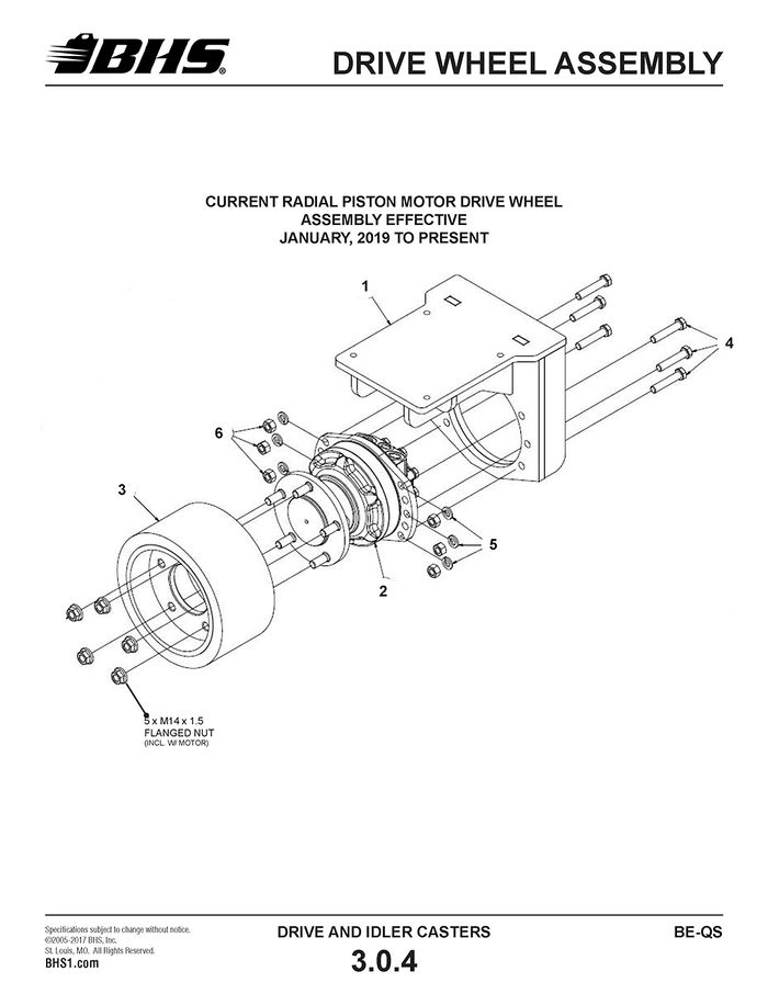
DRIVE WHEEL ASSEMBLY
ITEM | BHS PART NUMBER | DESCRIPTION | REF. KIT NO. | NOTES | NO. REQ |
REF | 43822005 | DRIVE WHEEL ASSEMBLY | 2 | ||
1 | 43825003 | GEARBOX DRIVE WHEEL MOUNT | |||
2 | HC0160 | 400CC RADIAL PISTON MOTOR | |||
3 | C0511 | WHEEL-POLY-10 X 5"-FLANGE MOUNT | |||
4 | HW0514 | BOLT-HHCS-1/2"-13 X 2 1/2" | |||
5 | HW0110 | WASHER-LOCK-1/2" | |||
6 | HW0007 | NUT HEX 1/2"-13 |
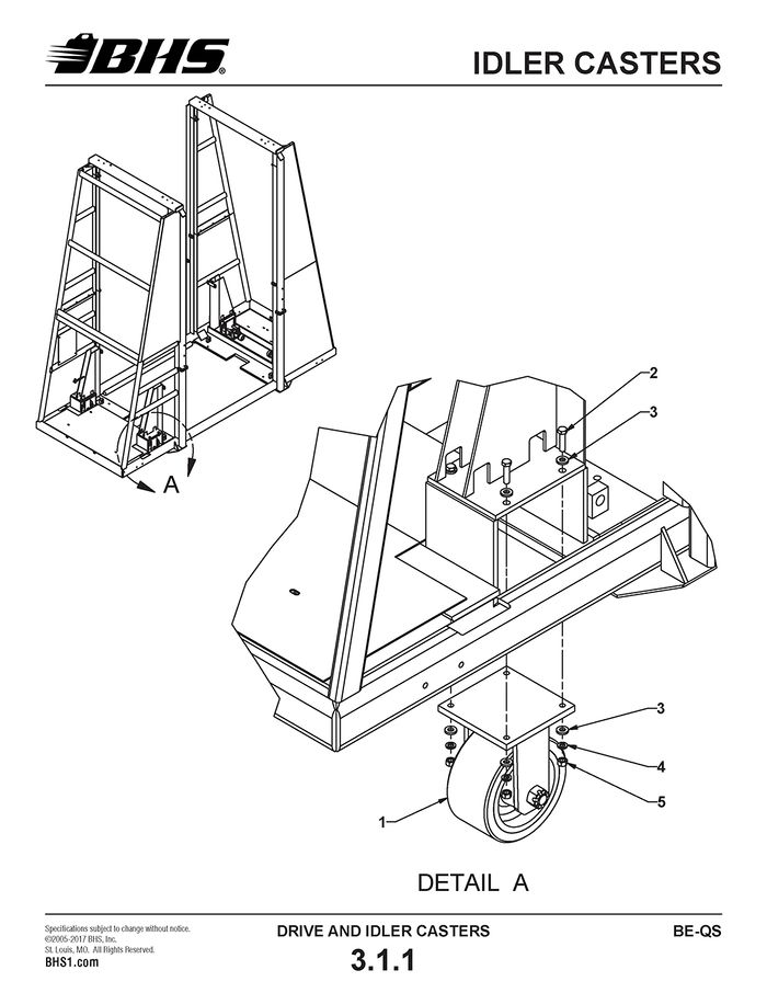
IDLER CASTERS
ITEM | BHS PART NUMBER | DESCRIPTION | REF. KIT NO. | NOTES | NO. REQ |
1 | C0500-1 | CASTER-RIGID-10" X 5"-POLY | 2 | ||
2 | HW0504 | BOLT-HHCS-1/2-13 X 2" | 8 | ||
3 | HW0112 | WASHER-FLAT-1/2"-SAE | 16 | ||
4 | HW0110 | WASHER-LOCK-1/2" | 8 | ||
5 | HW0007 | NUT-HEX-1/2-13 | 8 |
ELECTRICAL
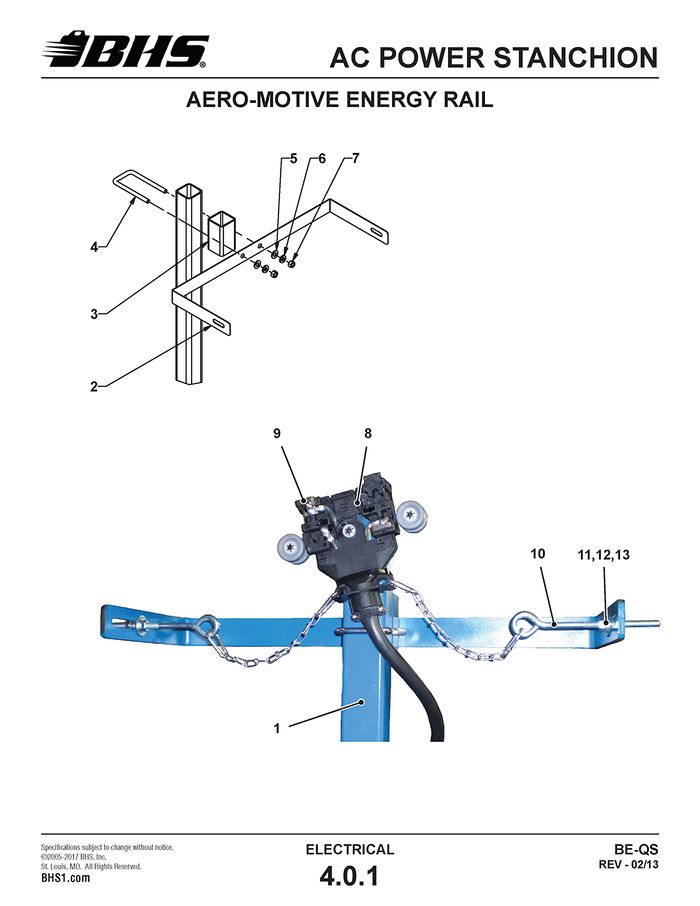
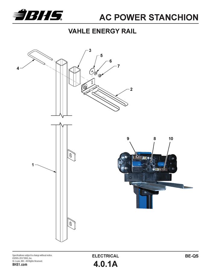
AC POWER STANCHION
ITEM | BHS PART NUMBER | DESCRIPTION | REF. KIT NO. | NOTES | NO. REQ |
1 | 43935002 | STANCHION-AC POWER | 1 | ||
2 | 46837014-2 | TOW ARM-COLLECTOR TROLLEY | 1 | ||
3 | 46838015 | SPACER-BLOCK-TOW ARM | 1 | ||
4 | HW1030 | U-BOLT-3/8-16 X 2" X 5"-SQUARE BEND | 1 | ||
5 | HW0108 | WASHER-FLAT-3/8"-SAE | 2 | ||
6 | HW0107 | WASHER-LOCK-3/8" | 2 | ||
7 | HW0005 | NUT-HEX-3/8-16 | 2 | ||
8 | BD0010 | TROLLEY-ENERGY RAIL | AERO-MOTIVE RAIL ONLY | 1 | |
9 | BD0100 | BRUSH-TROLLEY | 4 | ||
10 | HW1051 | EYE BOLT-3/16-16 X 5 1/2" | 2 | ||
11 | HW0126 | WASHER-FLAT-3/8"-FENDER | 4 | ||
12 | HW0107 | WASHER-LOCK-3/8" | 4 | ||
13 | HW0005 | NUT-HEX-3/8-16 | 4 |
† SEE SECTION 1.3.2 FOR MOUNTING HARDWARE
ITEM | BHS PART NUMBER | DESCRIPTION | REF. KIT NO. | NOTES | NO. REQ |
1 | 43935002 | STANCHION-AC POWER | 1 | ||
2 | BD0030 | TOW ARM-COLLECTOR TROLLEY | 1 | ||
3 | 46838015 | SPACER-BLOCK-TOW ARM | 1 | ||
4 | HW1054 | U-BOLT-5/16-18 X 2" X 5"-SQUARE BEND | 1 | ||
5 | HW0150 | WASHER-FLAT-5/16"-FENDER | 2 | ||
6 | HW0105 | WASHER-LOCK-5/16" | 2 | ||
7 | HW0004 | NUT-HEX-5/16-18 | 2 | ||
8 | BD0031 | TROLLEY-ENERGY RAIL | VAHLE RAIL ONLY | 1 | |
9 | BD0040 | BRUSH-PHASE | 3 | ||
10 | BD0041 | BRUSH-GROUND | 1 |
† SEE SECTION 1.3.2 FOR MOUNTING HARDWARE
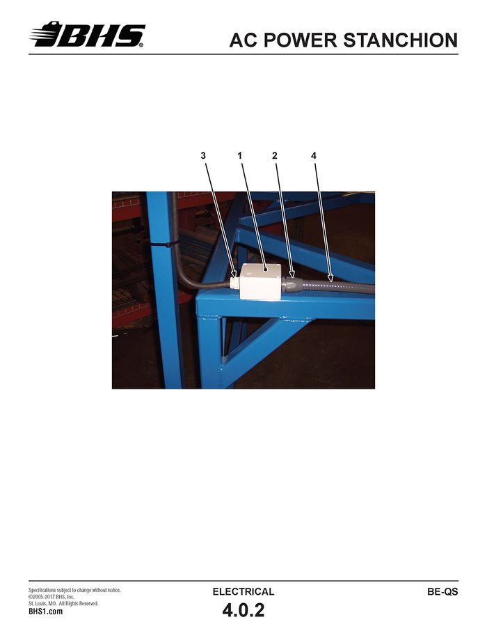
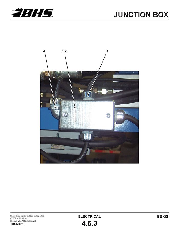
ITEM | BHS PART NUMBER | DESCRIPTION | REF. KIT NO. | NOTES | NO. REQ |
1 | E1329 | JUNCTION BOX-4" X 4" X 2" | 1 | ||
2 | E0662 | RESTRAINT-3/4"-LIQUIDTIGHT | 1 | ||
3 | E0632 | RESTRAINT-3/4" | GRIP SIZE .625 - .750 | 1 | |
4 | E0660 | CONDUIT-3/4"-LIQUIDTIGHT | † SEE NOTES | A/R | |
5 | E0618 | LOCKNUT-CONDUIT-3/4" | NOT SHOWN | 2 | |
6 | HW0212 | SCREW-RHMS-#10-24 X 1/2" | NOT SHOWN | 4 | |
7 | HW0102 | WASHER-FLAT-#10-SAE | NOT SHOWN | 4 |
† DUE TO DIFFERENT MACHINE SIZES AND POSSIBLE ORIENTATIONS, THIS PART IS CUT TO LENGTH FOR EACH INDIVIDUAL MACHINE.
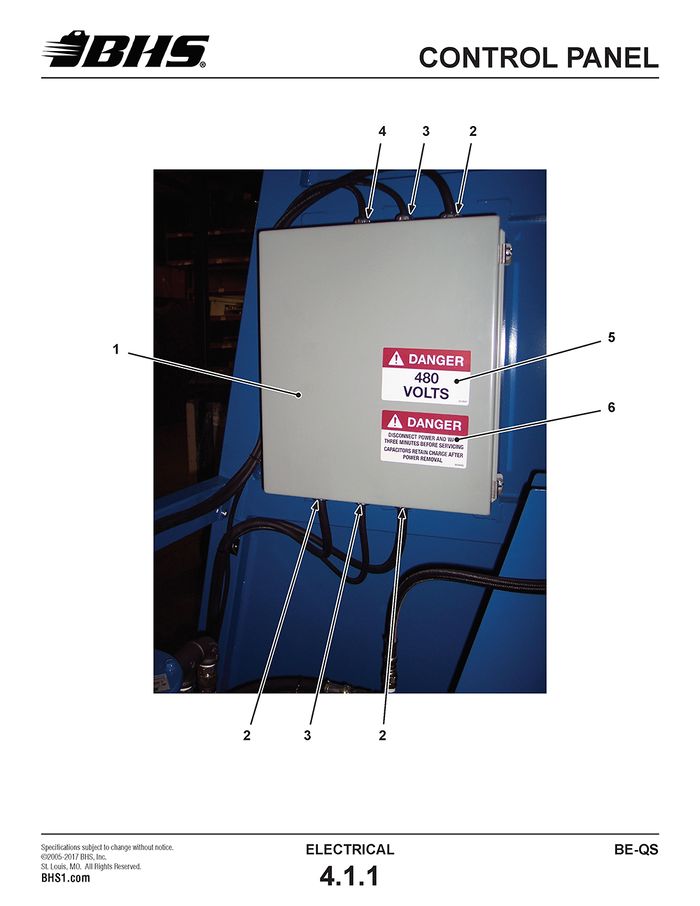
CONTROL PANEL
ITEM | BHS PART NUMBER | DESCRIPTION | REF. KIT NO. | NOTES | NO. REQ |
1 | E0638 | ENCLOSURE-CONTROL PANEL-16" X 14" X 6" | 1 | ||
2 | E0613 | RESTRAINT-3/4" | GRIP SIZE .500 - .625 | 3 | |
3 | E0616 | RESTRAINT-1/2" | GRIP SIZE .250 -.375 | 2 | |
4 | E0622 | RESTRAINT-1/2" | GRIP SIZE .450 - .500 | 1 | |
5 | 00196401 | LABEL-"DANGER-480 VOLTS" | 1 | ||
6 | 00196408 | LABEL-"DANGER-DISCONNECT POWER..." | 1 | ||
7 | E0617 | LOCKNUT-CONDUIT-1/2" | NOT SHOWN | 3 | |
8 | E0618 | LOCKNUT-CONDUIT-3/4" | NOT SHOWN | 3 | |
9 | HW0303 | BOLT-HHCS-1/4-20 X 1 " | MTG HARDWARE (NOT SHOWN) | 4 | |
10 | HW0104 | WASHER-FLAT-1/4"-SAE | MTG HARDWARE (NOT SHOWN) | 8 | |
11 | HW0103 | WASHER-LOCK-1/4" | MTG HARDWARE (NOT SHOWN) | 4 | |
12 | HW0002 | NUT-HEX-1/4-20 | MTG HARDWARE (NOT SHOWN) | 4 |
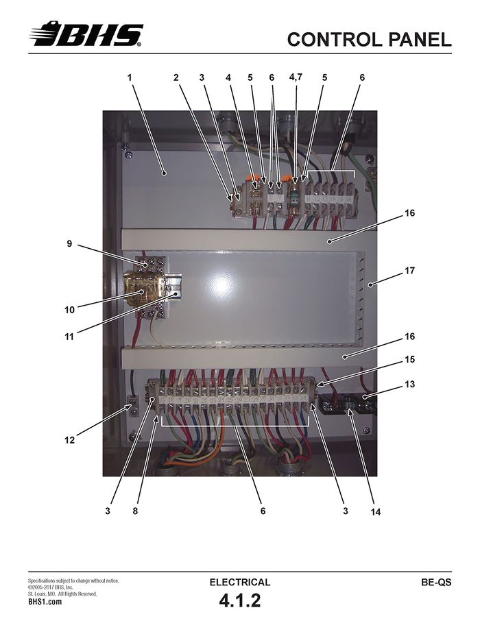
ITEM | BHS PART NUMBER | DESCRIPTION | REF. KIT NO. | NOTES | NO. REQ |
1 | E0640 | PANEL-COMPONENT MOUNTING | 1 | ||
2 | E1024 | TRACK-TERMINAL BLOCK | 6.5" | ||
3 | E1330 | END ANCHOR | 4 | ||
4 | E1338 | HOLDER-FUSE | 2 | ||
5 | E1331 | END BARRIER-FUSE | 2 | ||
6 | E1020 | TERMINAL BLOCK | 26 | ||
7 | FLM10 | FUSE | 10 AMP | 1 | |
8 | E1040 | END BARRIER | 1 | ||
9 | E1013 | SOCKET-RELAY-11 PIN | 1 | ||
10 | E1012 | RELAY-11 PIN | 1 | ||
11 | E0908 | TRACK-MOUNTING | 2.5" | ||
12 | 0E341 | GROUND LUG | 2 | ||
13 | E1016 | HOLDER-FUSE | 1 | ||
14 | FLM8 | FUSE | 8 AMP | 1 | |
15 | E1024 | TRACK-TERMINAL BLOCK | 8.75" | ||
16 | E1023 | WIRE WAY | 2 PIECES @ 11.625" | 23.25" | |
17 | E1023 | WIRE WAY | 6.875" | ||
18 | HW0130 | SCREW-RHMS-#8-32 X 1/2" | 15 | ||
19 | HW0133 | WASHER-FLAT-#8-SAE | 15 | ||
20 | HW1032 | NUT-NILN-#8-32 | 15 |
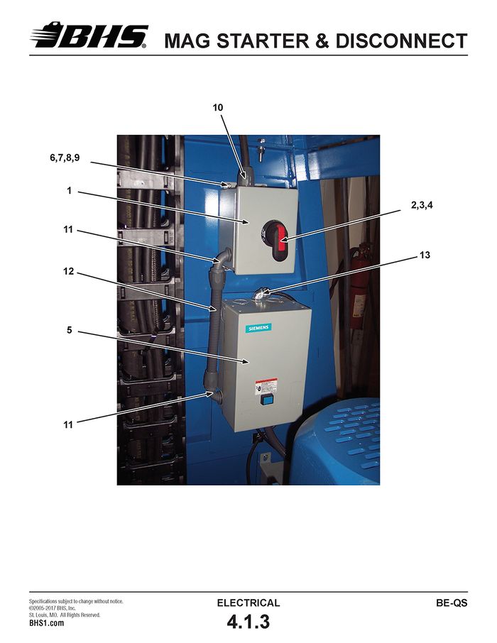
MAG STARTER & DISCONNECT
ITEM | BHS PART NUMBER | DESCRIPTION | REF. KIT NO. | NOTES | NO. REQ |
1 | E1336 | ENCLOSURE-DISCONNECT | 1 | ||
2 | E0127 | BASE-DISCONNECT | † SEE NOTES (NOT SHOWN) | 1 | |
3 | E0123-1 | HANDLE-DISCONNECT | † SEE NOTES | 1 | |
4 | E0124-2 | SHAFT-DISCONNECT | †† SEE NOTES (NOT SHOWN) | 1 | |
5 | E0125 | MAGNETIC STARTER-NEMA 2 | REPLACES 14FSH32BA | 1 | |
6 | HW0303 | BOLT-HHCS-1/4-20 X 1" | 7 | ||
7 | HW0104 | WASHER-FLAT-1/4"-SAE | 14 | ||
8 | HW0103 | WASHER-LOCK-1/4" | 7 | ||
9 | HW0002 | NUT-HEX-1/4-20 | 7 | ||
10 | E0662 | RESTRAINT-3/4"-LIQUIDTIGHT | 2 | ||
11 | E0661 | RESTRAINT-3/4"-90 DEG-LIQUIDTIGHT | 2 | ||
12 | E0660 | CONDUIT-3/4"-LIQUIDTIGHT | 12" | ||
13 | E0623 | RESTRAINT-1/2"-90 DEG | GRIP SIZE .250 - .375 | 1 | |
14 | E0616 | RESTRAINT-1/2" | GRIP SIZE .250 - .375 | 1 | |
15 | E0617 | LOCKNUT-CONDUIT-1/2" | NOT SHOWN | 2 | |
16 | E0618 | LOCKNUT-CONDUIT-3/4" | NOT SHOWN | 4 | |
17 | 3704 | KNOCKOUT WASHER-REDUCER-1" TO 3/4" | NOT SHOWN | 4 | |
18 | E0128 | ADAPTER-SHAFT | † SEE NOTES | A/R |
† FOR UNITS BUILT PRIOR TO 01/12/10, A SHAFT ADAPTER (ITEM# 18) IS REQUIRED WHEN REPLACING EITHER ITEM #2 OR ITEM #3.
† † FOR UNITS BUILT PRIOR TO 01/12/10, ITEM #’S 2 AND 3 MUST BE REPLACED IF REPLACING ITEM #4.
IF THERE IS ANY QUESTION AS TO THE THE ITEMS NEEDED WHEN ORDERING A NEW DISCONNECT BASE, SHAFT OR HANDLE, PLEASE CONTACT BHS TECH SUPPORT WITH THE MANUFACTURER’S PART NUMBER OF THE DISCONNECT BASE AND HANDLE.
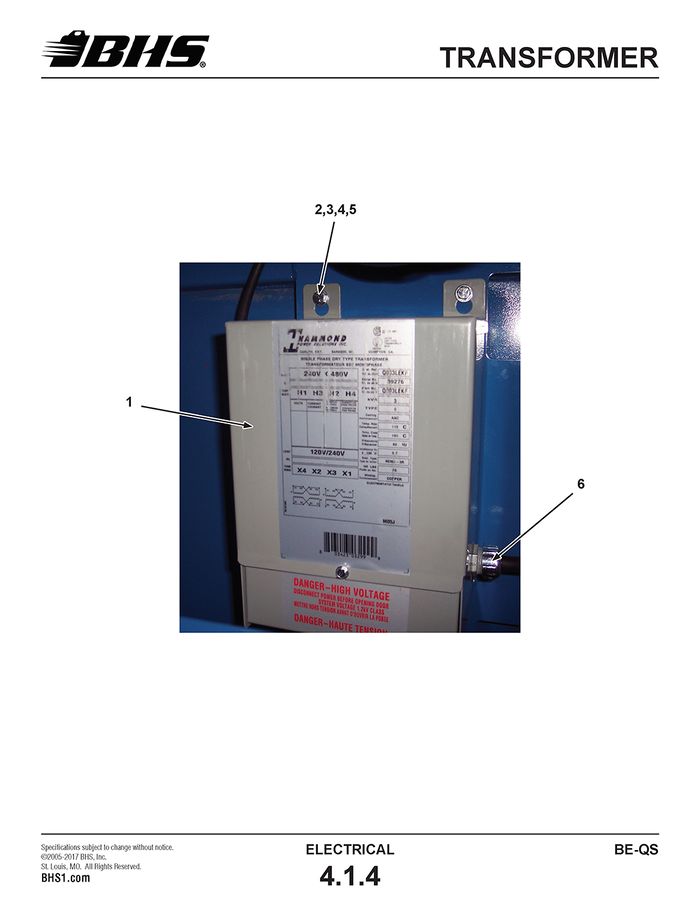
TRANSFORMER
ITEM | BHS PART NUMBER | DESCRIPTION | REF. KIT NO. | NOTES | NO. REQ |
1 | E0220 | TRANSFORMER-3Kva | 1 | ||
2 | HW0303 | BOLT-HHCS-1/4-20 X 1 " | 3 | ||
3 | HW0104 | WASHER-FLAT-1/4-"SAE | 6 | ||
4 | HW0103 | WASHER-LOCK-1/4" | 3 | ||
5 | HW0002 | NUT-HEX-1/4-20 | 3 | ||
6 | E0622 | RESTRAINT-1/2" | GRIP SIZE .450 - .500 | 1 | |
7 | E0623 | RESTRAINT-1/2"-90 DEG | GRIP SIZE .250 - .375 (NOT SHOWN) | 1 | |
8 | E0617 | LOCKNUT-CONDUIT-1/2" | NOT SHOWN | 2 |
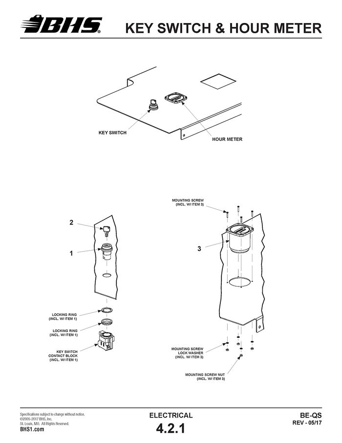
KEY SWITCH & HOUR METER
ITEM | BHS PART NUMBER | DESCRIPTION | REF. KIT NO. | NOTES | NO. REQ |
1 | E0327 | KEYED ACTUATOR ASSEMBLY | INCL. 2 KEYS & CONTACT BLOCK | 1 | |
2 | E0351 | KEY-REPLACEMENT | INCLUDES 2 KEYS | A/R | |
3 | E0309-1 | HOUR METER | † INCL. MOUNTING HARDWARE | 1 |
† CURRENT HOUR METER IS 3-BOLT VERSION. REPLACEMENT OF 4-BOLT VERSION WILL REQUIRE NEW MOUNTING HOLES BE DRILLED IN DASHBOARD.
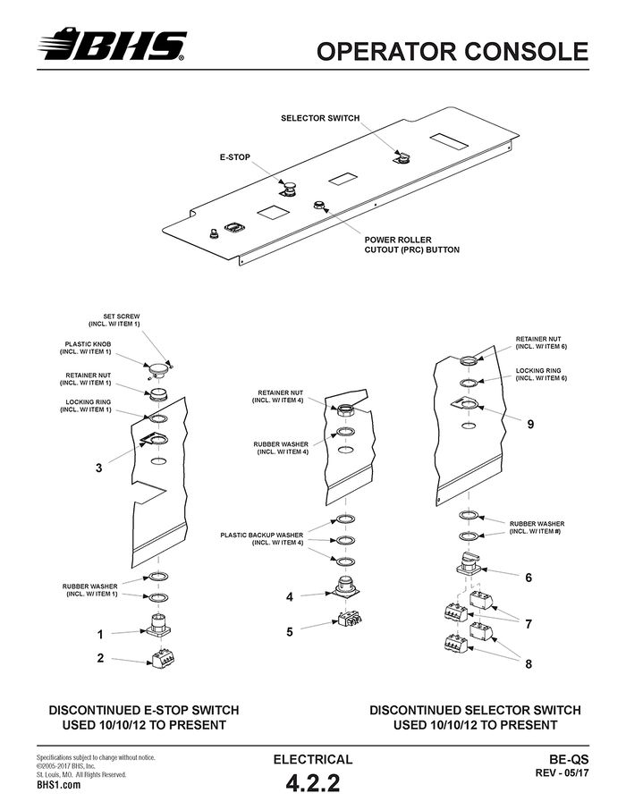
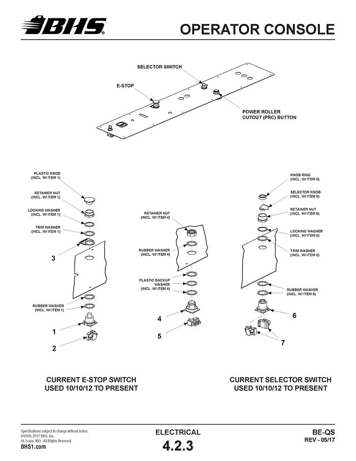
OPERATOR CONSOLE
ITEM | BHS PART NUMBER | DESCRIPTION | REF. KIT NO. | NOTES | NO. REQ |
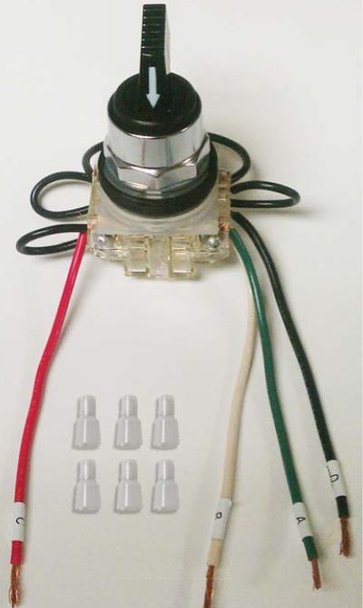
1 | N/A | ACTUATOR-MUSHROOM HEAD | † SEE NOTES | 1 | |
2 | N/A | CONTACT BLOCK-N/C | † SEE NOTES | 1 | |
3 | E1315 | LEGEND PLATE-EMERGENCY STOP | 1 | ||
4 | E0308 | ACTUATOR-PUSH BUTTON | 1 | ||
5 | E0358 | CONTACT BLOCK-N/C | 1 | ||
6 | N/A | SWITCH-SELECTOR-3 POSITION | ON-OFF-ON, †† SEE NOTES | 1 | |
7 | N/A | CONTACT BLOCK-N/O | †† SEE NOTES | 2 | |
8 | N/A | CONTACT BLOCK-N/C | †† SEE NOTES | 2 | |
9 | E0812 | LEGEND PLATE-VACUUM | 1 | ||
E0812-M | LEGEND PLATE-MAGNET | 1 |
† PARTS NO LONGER AVAILABLE. MUST ORDER NEW E-STOP SWITCH KIT 80432002. SEE SECT. 4.2.3
†† PARTS NO LONGER AVAILABLE. MUST ORDER NEW SELECTOR SWITCH KIT 80232001. SEE SECT. 4.2.3
ITEM | BHS PART NUMBER | DESCRIPTION | REF. KIT NO. | NOTES | NO. REQ |
1 | E1081 | ACTUATOR-MUSHROOM HEAD | 80432002 | 1 | |
2 | E1085 | CONTACT BLOCK-N/C | 80432002 | 1 | |
3 | E1315 | LEGEND PLATE-EMERGENCY STOP | 1 | ||
4 | E0308 | ACTUATOR-PUSH BUTTON | 1 | ||
5 | E0358 | CONTACT BLOCK-N/C | 1 | ||
6 | E1083 | SWITCH-SELECTOR-3 POSITION | 80232001 | OFF-ON-OFF | 1 |
7 | E1080 | CONTACT BLOCK-N/O & N/C | 80232001 | 2 |
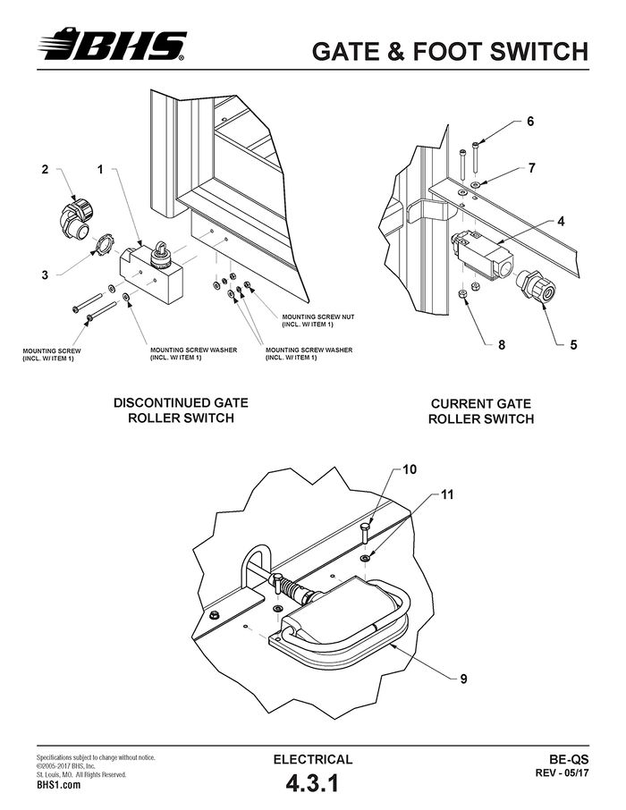
GATE & FOOT SWITCH
ITEM | BHS PART NUMBER | DESCRIPTION | REF. KIT NO. | NOTES | NO. REQ |
1 | E0355 | SWITCH-GATE | INCL. MOUNTING HARDWARE | 1 | |
2 | E0623 | RESTRAINT-1/2"-90 DEG | GRIP SIZE .250" TO .375" | 1 | |
3 | E0617 | LOCKNUT-CONDUIT-1/2" | 1 | ||
4 | YE0305 | SWITCH-GATE | 1 | ||
5 | E0616 | RESTRAINT-1/2" | GRIP SIZE .250" TO .375" | 1 | |
6 | SS0111 | SCREW-SHCS-#8-32 X 1 1/2" | 2 | ||
7 | SS0303 | WASHER-FLAT-#8 | 2 | ||
8 | SS0203 | NUT-NILN-#8-32 | 2 | ||
9 | E0301-1 | SWITCH-FOOT OPERATED | 1 | ||
10 | HC0303 | BOLT-HHCS-1/4-20 X 1" | 2 | ||
11 | HC0103 | WASHER-1/4"-LOCK | 2 |
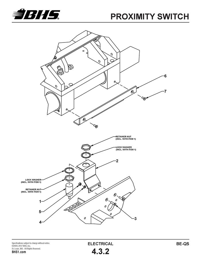
PROXIMITY SWITCH
ITEM | BHS PART NUMBER | DESCRIPTION | REF. KIT NO. | NOTES | NO. REQ |
1 | E0314 | SENSOR-PROXIMITY-30MM | 1 | ||
2 | 43017027-2 | BRACKET-PROXIMITY SENSOR | 1 | ||
3 | HW0306 | BOLT-FHSCS-1/4-20 X 1" | 2 | ||
4 | HW0103 | WASHER-LOCK-1/4" | 2 | ||
5 | HW0002 | NUT-HEX-1/4-20 | 2 | ||
6 | 43017037-2 | ANGLE-PROXIMITY SENSOR TARGET | 1 | ||
7 | HW0341 | BOLT-FHSCS-1/4-20 X 5/8" | 2 |
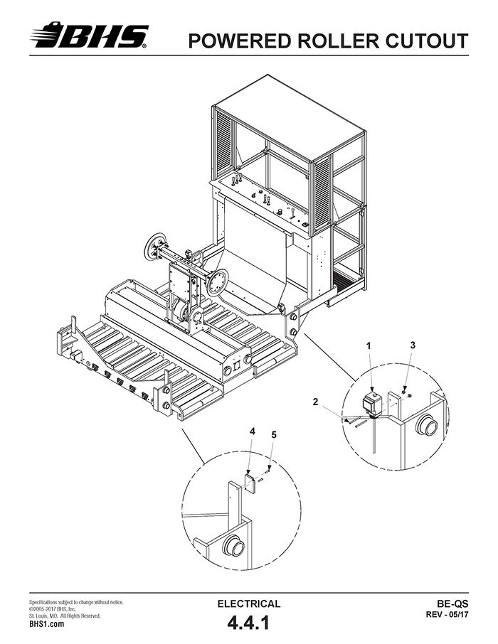
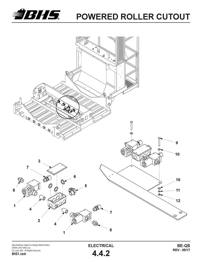
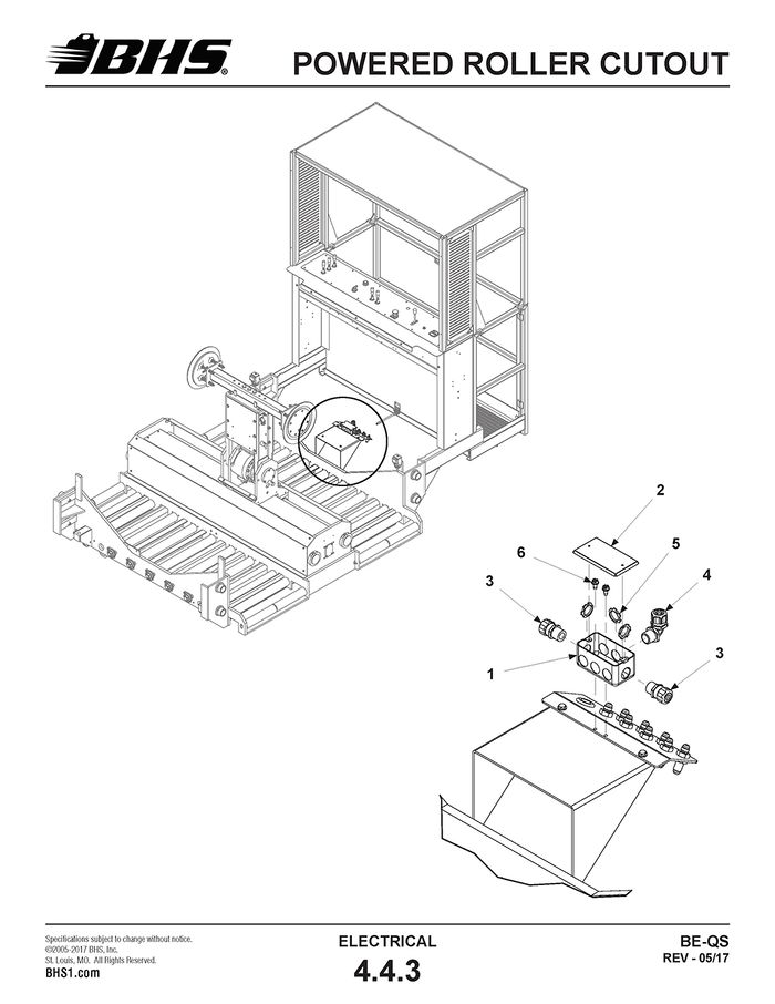
POWERED ROLLER CUTOUT
ITEM | BHS PART NUMBER | DESCRIPTION | REF. KIT NO. | NOTES | NO. REQ |
1 | E1321A | PHOTO EYE | † POLARIZED | 2 | |
2 | HW0216 | SCREW-#10-24 X 2" | 4 | ||
3 | SS0202 | NUT-NILN-#10-24 | 4 | ||
4 | E1321-R | REFLECTOR | 2 | ||
5 | SS0803 | SCREW-RHMS-#6-32 X 5/8" | 4 |
† POLARIZED PHOTO EYE RECOMMENDED TO PREVENT POTENTIAL OPERATIONAL ISSUES WITH VERY SMOOTH OR SHINY BATTERY CASES.
ITEM | BHS PART NUMBER | DESCRIPTION | REF. KIT NO. | NOTES | NO. REQ |
1 | HC0281 | SOLENOID VALVE | 2 | ||
2 | E0611 | JUNCTION BOX-4" X 2" X 2" | 1 | ||
3 | E0612 | COVER-JUNCTION BOX | 1 | ||
4 | BI0001 | NIPPLE-CLOSE-#8 NPT | 2 | ||
5 | E0623 | RESTRAINT-1/2"-90 DEG | GRIP SIZE .250 TO .375 | 1 | |
6 | E0617 | LOCKNUT-CONDUIT-1/2" | 3 | ||
7 | H1600 | ADAPTER-90 DEG-#6 JICM X #8 SAEM | 2 | ||
8 | H1546 | ADAPTER-#6 JICM X #8 SAEM | 2 | ||
9 | HW0308 | BOLT-HHCS-1/4-20 X 2 1/2" | 2 | ||
10 | HW0104 | WASHER-FLAT-1/4"-SAE | 4 | ||
11 | HW0103 | WASHER-LOCK-1/4" | 2 | ||
12 | HW0002 | NUT-HEX-1/4-20 | 2 |
ITEM | BHS PART NUMBER | DESCRIPTION | REF. KIT NO. | NOTES | NO. REQ |
1 | E0611 | JUNCTION BOX-4" X 2" X 2" | 1 | ||
2 | E0612 | COVER-JUNCTION BOX | 1 | ||
3 | E0616 | RESTRAINT-1/2" | GRIP SIZE .250 TO .375 | 2 | |
4 | E0623 | RESTRAINT-1/2"-90 DEG | GRIP SIZE .250 TO .375 | 1 | |
5 | E0617 | LOCKNUT-CONDUIT-1/2" | NOT SHOWN | 4 | |
6 | HW0301 | BOLT-SELF TAP "F"-1/4-20 X 1/2" | 2 |
JUNCTION BOX
ITEM | BHS PART NUMBER | DESCRIPTION | REF. KIT NO. | NOTES | NO. REQ |
1 | E1342 | ENCLOSURE-6" X 6" X 4" | NO HOLES DRILLED | 1 | |
2 | E0623 | RESTRAINT-1/2"-90 DEG | GRIP SIZE .250 - .375 | 3 | |
3 | E0608-1 | RESTRAINT-1/2"-90 DEG | GRIP SIZE .450 - .560 | 1 | |
4 | E0622 | RESTRAINT-1/2" | GRIP SIZE .450 - .500 | 1 | |
5 | 00196404 | DECAL-"DANGER-120 VOLTS" | 1 | ||
6 | E0617 | LOCKNUT-CONDUIT-1/2" | NOT SHOWN | 5 | |
7 | HW0301 | BOLT-SELF TAP "F"-1/4-20 X 1/2" | MTG HARDWARE (NOT SHOWN) | 4 |
JUNCTION BOX PANEL
ITEM | BHS PART NUMBER | DESCRIPTION | REF. KIT NO. | NOTES | NO. REQ |
1 | E0639 | PANEL-COMPONENT MOUNTING | WITHOUT HOLES | 1 | |
2 | E1024 | TRACK-TERMINAL BLOCK | 4 7/8" | 1 | |
3 | E1020 | TERMINAL BLOCK | 8 | ||
4 | E1330 | END ANCHOR | 2 | ||
5 | E1040 | END BARRIER | 1 | ||
6 | E0341 | GROUND LUG | 1 | ||
7 | HW0130 | SCREW-RHMS-#8-32 X 1/2" | 2 FOR TRACK MOUNTING | 3 | |
8 | HW0132 | NUT-NILN-#8-32 | 2 FOR TRACK MOUNTING | 3 | |
9 | HW0133 | WASHER-FLAT-#8-SAE | 2 FOR TRACK MOUNTING | 3 |
JUNCTION BOX
ITEM | BHS PART NUMBER | DESCRIPTION | REF. KIT NO. | NOTES | NO. REQ |
1 | E0611 | BOX-JUNCTION-4" X 2" X 2" | 1 | ||
2 | E0612 | COVER-JUNCTON BOX | 1 | ||
3 | E0616 | RESTRAINT-1/2" | GRIP SIZE .250 TO .375 | 3 | |
4 | E0623 | RESTRAINT-1/2"-90 DEG | GRIP SIZE .250 TO .375 | 1 | |
5 | E0617 | LOCKNUT-CONDUIT-1/2" | NOT SHOWN | 4 |
120V RECEPTACLE
ITEM | BHS PART NUMBER | DESCRIPTION | REF. KIT NO. | NOTES | NO. REQ |
1 | E0611 | JUNCTION BOX-4" X 2" X 2" | 1 | ||
2 | E0622 | RESTRAINT-1/2" | GRIP SIZE .450 TO .560 | 1 | |
3 | E0617 | LOCKNUT-CONDUIT-1/2" | 1 | ||
4 | E0650 | RECEPTACLE-DUPLEX | †20A | 1 | |
5 | E0651 | COVER-RECEPTACLE-DUPLEX | 1 | ||
6 | E0655 | RECEPTACLE-GFCI | 20A | 1 | |
7 | E0656 | COVER-RECEPTACLE-GFCI | 1 | ||
8 | E0654 | JUNCTION BOX-4" X 4" X 2" | 1 | ||
9 | E0657 | COVER-RECEPTACLE-DUPLEX/GFCI | 1 | ||
10 | HW0301 | BOLT-SELF TAP "F"-1/4-20 X 1/2" | MTG HARDWARE (NOT SHOWN) | A/R |
† IF DUPLEX RECEPTACLE HAS SPLIT FEED (1 SET OF BLACK & WHITE WIRES FOR EACH PLUG), THE BREAK-OFF FIN MUST BE REMOVED PRIOR TO INSTALLATION.
SCHEMATICS
HYDRAULICS
POWER UNIT & RESERVOIR
ITEM | BHS PART NUMBER | DESCRIPTION | REF. KIT NO. | NOTES | NO. REQ |
1 | HC0353 | FILTER CARTRIDGE | 1 | ||
2 | HC0308 | FILLER/BREATHER ASSEMBLY | 1 | ||
3 | HW0209 | SCREW-RHMS-10-32 X 1/2" | 6 | ||
4 | 43946002 | CARTRIDGE-COMPENSATOR | 1 | ||
5 | HC0277 | SNUBBER-PRESSURE | 1 | ||
6 | HC0318 | GUAUGE-PRESSURE | 1 | ||
7 | HC0340 | GAUGE-SIGHT | W/ THERMOMETER | 1 | |
8 | H0210 | ADAPTER-#24 SAE X #24 FNPT | 1 | ||
9 | H0211 | REDUCER-#24 NPT X #12 FNPT | 1 | ||
10 | BI0002 | NIPPLE-CLOSE-#12 NPT | 1 | ||
11 | BI0301 | TEE-#12 FNPT | 1 | ||
12 | BI0107 | ELBOW-STR-90 DEG-#12 NPT | 1 | ||
13 | H1503 | ADAPTER-#12 JICM X #12 MNPT | 2 | ||
14 | HW0403 | BOLT-HHCS-3/8-16 X 1 1/4" | MOUNTING HARDWARE (NOT SHOWN) | 4 | |
15 | HW0108 | WASHER-FLAT-3/8"-SAE | 8 | ||
16 | HW0107 | WASHER-LOCK-3/8" | 4 | ||
17 | HW0005 | NUT-HEX-3/8-16 | 4 |
† CONSULT FACTORY WITH DATA PLATE INFORMATION FOR ANY COMPONENTS NOT LISTED ABOVE.
RESERVOIR CHECK VALVE
ITEM | BHS PART NUMBER | DESCRIPTION | REF. KIT NO. | NOTES | NO. REQ |
1 | HC0288 | VALVE-CHECK | INCL. CARTRIDGE | 1 | |
2 | H1523 | ADAPTER-#16 JICM X #16 SAEM | 1 | ||
3 | H1603 | ADAPTER-90 DEG-#16 JICM X #16 SAEM | 2 | ||
4 | † | CARTRIDGE-REPLACEMENT | A/R |
† CONSULT FACTORY.
POWER UNIT (25 HP)
ITEM | BHS PART NUMBER | DESCRIPTION | REF. KIT NO. | NOTES | NO. REQ |
1 | E0045 | MOTOR-ELECTRIC-25 HP | 1 | ||
2 | HC0366 | ADAPTER-PUMP TO MOTOR | 1 | ||
3 | HC0365 | PUMP-PISTON-100CC | 1 | ||
4 | HC0367-M | COUPLING BODY-M500-1 7/8" BORE | MOTOR SIDE | 1 | |
5 | HC0367-I | SPIDER-COUPLING INSERT | 1 | ||
6 | HC0367-P | COUPLING BODY-M500-1 1/2" BORE | PUMP SIDE | 1 | |
7 | HW0602 | BOLT-HHCS-5/8-11 X 2" | 2 | ||
8 | HW0113 | WASHER-LOCK-5/8" | 2 | ||
9 | H1622 | ADAPTER-90 DEG-#12 JICM X #12 SAEM | 1 | ||
10 | HE0751 | ADAPTER-45 DEG-#40 FLANGE X 2 1/2" BARB | 1 | ||
11 | H0030 | ADAPTER-SPLIT FLANGE | 2-PC ADAPTER, W/ O-RING | 1 | |
12 | H0211 | ADAPTER-#12 NPT X #24 NPT | 1 | ||
13 | E0662 | RESTRAINT-3/4"-LIQUIDTIGHT | 1 | ||
14 | HC0297 | BLOCK-CHECK VALVE | INCL. CARTRIDGE | 1 | |
15 | CARTRIDGE-CHECK VALVE | REPLACEMENT CARTRIDGE | A/R | ||
16 | H0031 | ADAPTER-FLANGE-#20 SAE | INCL. O-RING | 1 | |
17 | H1525 | ADAPTER-#16 JIC X #20 SAE | 1 | ||
18 | H0300 | ELBOW-STR-90 DEG-#4 NPT | 1 | ||
19 | H0001 | NIPPLE-#4 NPT | 1 | ||
20 | H0100 | COUPLING-#4 NPT | 1 | ||
21 | HC0318 | GAUGE-PRESSURE | 1 | ||
22 | HW0514 | BOLT-HHCS-1/2-13 X 2 1/2" | 4 | ||
23 | HW0112 | WASHER-FLAT-1/2"-SAE | 8 | ||
24 | HW0110 | WASHER-LOCK-1/2" | 4 | ||
25 | HW0007 | NUT-HEX-1/2-13 | 4 |
RESERVOIR (60 GAL)
ITEM | BHS PART NUMBER | DESCRIPTION | REF. KIT NO. | NOTES | NO. REQ |
REF | 43942003 | 60 GAL VERTICAL RESERVOIR ASSY | INCL. ITEMS 1 -10 | A/R | |
1 | HC0542 | GASKET-CHANNEL | SOLD BY LENGTH | 7’ | |
2 | HC0340 | GUAGE-SIGHT | 1 | ||
3 | HC0308 | FILLER/BREATHER ASSEMBLY | 1 | ||
4 | HW0209 | SCREW-RHMS-10-32 X 1/2" | 6 | ||
5 | HC0361 | HOUSING-FILTER | 1 | ||
6 | HW0402 | BOLT-HHCS-3/8-16 X 1" | 8 | ||
7 | HW0403 | BOLT-HHCS-3/8-16 X 1 1/4" | 4 | ||
8 | HW0108 | WASHER-FLAT-3/8"-SAE | 12 | ||
9 | H0208 | PLUG-#12 NPT | 2 | ||
10 | BI0015 | NIPPLE-#12 NPT X 24" | 1 | ||
11 | HC0354 | CARTRIDGE-FILTER | 10 MICRON FILTRATION | 1 | |
12 | H1644 | PLUG-#24 SAE | 1 | ||
13 | H0202 | REDUCER-#24 SAE X #12 SAE | 1 | ||
14 | BI0020 | NIPPLE-#12 NPT X 3" | 1 | ||
15 | BI0301 | TEE-#12 FNPT | 1 | ||
16 | BI0107 | ELBOW-STR-90 DEG-#12 NPT | 1 | ||
17 | H1503 | ADAPTER-#12 JICM X #12 MNPT | 3 | ||
18 | HC0298 | VALVE-BALL-#40 SAE (2 1/2") | 1 | ||
19 | HE0750 | ADAPTER-#40 SAE X 2 1/2" BARB | 1 | ||
20 | HW0402 | BOLT-HHCS-3/8-16 X 1" | MOUNTING HARDWARE (NOT SHOWN) | 4 | |
21 | HW0108 | WASHER-FLAT-3/8"-SAE | 8 | ||
22 | HW0107 | WASHER-LOCK-3/8" | 4 | ||
23 | HW0005 | NUT-HEX-3/8-16 | 4 |
RESERVOIR SUCTION HOSE
ITEM | BHS PART NUMBER | DESCRIPTION | REF. KIT NO. | NOTES | NO. REQ |
1 | HE0015 | HOSE-SUCTION-2 1/2" | |||
2 | HE0016 | CLAMP-HOSE-2 1/2" | †SEE NOTES | 4 |
† SPECIAL CRIMP TOOL REQUIRED TO PROPERLY INSTALL CLAMPS.
VALVE ASSEMBLY
ITEM | BHS PART NUMBER | DESCRIPTION | REF. KIT NO. | NOTES | NO. REQ |
REF | HC0255-1 | LEVER VALVE RETRO KIT | † EFFECTIVE PRIOR TO 2006 | A/R | |
1 | HC0257 | VALVE-LEVER | EFFECTIVE FROM 2006 - PRES. | 1 | |
2 | HC0252 | MANIFOLD-D05-1 BANK | 1 | ||
3 | HW0318 | BOLT-SHCS-1/4-20 X 1 1/2" | 4 | ||
4 | H1642 | PLUG-#12 SAE | 1 | ||
5 | H1542 | ADAPTER-#12 JICM X #12 SAEM | 1 | ||
6 | H1606 | ADAPTER-90 DEG-#8 JICM X #8 SAEM | 1 | ||
7 | H1110 | ADAPTER-90 DEG-#12 JICM X #8 SAEM | 1 | ||
8 | H1623 | ADAPTER-90 DEG-LL-#12 JICM X #12 SAEM | 1 | ||
9 | H0610 | ADAPTER-45 DEG-#12 JICSW X #12 JICM | 1 | ||
10 | HW0303 | BOLT-HHCS-1/4-20 X 1" | 4 | ||
11 | HW0104 | WASHER-FLAT-1/4"-SAE | 8 | ||
12 | HW0103 | WASHER-LOCK-1/4" | 4 | ||
13 | HW0002 | NUT-HEX-1/4-20 | 4 | ||
14 | 43817085 | PLATE-ADAPTER-VALVE | † NOT SHOWN | 1 | |
15 | SS0104 | BOLT-SHCS-1/4-20 X 5/8"-SST | † NOT SHOWN | 4 | |
16 | SS0300 | WASHER-FLAT-1/4"-SAE-SST | † NOT SHOWN | 4 |
† KIT INCLUDES ITEMS 1 & 14-16. MINOR MODIFICATIONS TO THE DASH BOARD REQUIRED.
ITEM | BHS PART NUMBER | DESCRIPTION | REF. KIT NO. | NOTES | NO. REQ |
1 | HC0233 | VALVE-LEVER | 2 | ||
2 | HC0251 | MANIFOLD-D03-2 BANK | 1 | ||
3 | H1545 | ADAPTER-#10 JICM X #10 SAEM | 3 | ||
4 | H1606 | ADAPTER-90 DEG-#8 JICM X #8 SAEM | 2 | ||
5 | H1600 | ADAPTER-90 DEG-#6 JICM X #8 SAEM | 2 | ||
6 | H1587 | ADAPTER-#6 JICSW X #4 MNPT | 2 | ||
7 | HC0211 | VALVE-ADJUSTABLE FLOW CONTROL | 2 | ||
8 | H1504 | ADAPTER-#6 JICM X #4 MNPT | 2 | ||
9 | H1640 | PLUG-#6 SAE | 1 | ||
10 | HW0301 | BOLT-SELF TAP "F"-1/4-20 X 1/2" | 4 | ||
11 | 43817033-2 | RISER PLATE | 1 | ||
12 | HW0303 | BOLT-HHCS-1/4-20 X 1" | 4 | ||
13 | HW0104 | WASHER-FLAT-1/4"-SAE | 8 | ||
14 | HW0103 | WASHER-LOCK-1/4" | 4 | ||
15 | HW0002 | NUT-HEX-1/4-20 | 4 | ||
16 | H1641 | PLUG-#10 SAE | 1 | ||
17 | HC0233-SK | SEAL KIT | FOR ITEM 1 (NOT SHOWN) | A/R |
ITEM | BHS PART NUMBER | DESCRIPTION | REF. KIT NO. | NOTES | NO. REQ |
1 | HC0233 | VALVE-LEVER | 3 | ||
2 | HC0250 | MANIFOLD-D03-3 BANK | 1 | ||
3 | H1610 | ADAPTER-90 DEG-#10 JICM X #10 SAEM | 2 | ||
4 | H1565 | ADAPTER-45 DEG-#6 JICM X #4 MNPT | 2 | ||
5 | H1000 | ADAPTER-#8 SAEM X #4 FNPT | 4 | ||
6 | H0001 | NIPPLE-#4 NPT | 4 | ||
7 | HC0247 | FLOW REGULATOR-2.25 GPM | †SEE NOTES | 4 | |
8 | H1504 | ADAPTER-#6 JICM X #4 MNPT | 2 | ||
9 | H1640 | PLUG-#6 SAE | 1 | ||
10 | H1540 | ADAPTER-#8 JICM X #8 SAEM | 2 | ||
11 | HW0301 | BOLT-SELF TAP "F"-1/4-20 X 1/2" | 4 | ||
12 | 43817034-2 | RISER PLATE | 1 | ||
13 | HW0303 | BOLT-HHCS-1/4-20 X 1" | 4 | ||
14 | HW0104 | WASHER-FLAT-1/4"-SAE | 8 | ||
15 | HW0103 | WASHER-LOCK-1/4" | 4 | ||
16 | HW0002 | NUT-HEX-1/4-20 | 4 | ||
17 | HC0233-SK | SEAL KIT | FOR ITEM 1 (NOT SHOWN) | A/R |
† UNITS BUILT PRIOR TO JANUARY, 2017 EQUIPPED WITH ADJUSTABLE FLOW CONTROLS. FIXED FLOW REGULATORS ARE DIRECT REPLACEMENT FOR ADJUSTABLE FLOW CONTROLS.
LIFT CYLINDER
ITEM | BHS PART NUMBER | DESCRIPTION | REF. KIT NO. | NOTES | NO. REQ |
1 | 43922001 | CLEVIS ASSEMBLY | 4 | ||
2 | HC0430 | CYLINDER-LIFT | NEAR RIGHT / FAR LEFT | 2 | |
HC0431 | CYLINDER-LIFT | NEAR LEFT / FAR RIGHT | 2 | ||
3 | HW0813 | SCREW-SHSS-3/8-16 X 1/2" | NYLON TIPPED | 8 | |
4 | H1612 | ADAPTER-90 DEG-#8 JICM X #10 SAEM | 2 | ||
5 | HC0450 | VELOCITY FUSE | 4 | ||
6 | H1647 | ADAPTER-90 DEG-#10 SAEM X #8 FNPT | 4 |
NON-INTER FLOW MANIFOLD
ITEM | BHS PART NUMBER | DESCRIPTION | REF. KIT NO. | NOTES | NO. REQ |
1 | HC0285 | CARTRIDGE-CHECK VALVE | 8 | ||
2 | H1622 | ADAPTER-90 DEG-#12 JICM X #12 SAEM | 2 | ||
3 | H1560 | ADAPTER-45 DEG-#8 JICM X #8 SAEM | 4 | ||
4 | HW0334 | BOLT-HHCS-5/16-18 X 3 1/2" | 2 | ||
5 | HW0106 | WASHER-FLAT-5/16"-SAE | 4 | ||
6 | HW0105 | WASHER-LOCK-5/16" | 2 | ||
7 | HW0004 | NUT-HEX-5/16-18 | 2 |
DOWN-SPEED VALVES
ITEM | BHS PART NUMBER | DESCRIPTION | REF. KIT NO. | NOTES | NO. REQ |
1 | HC0286 | VALVE-FLOW CONTROL | PRESSURE COMPENSATED | 1 | |
1a | 43946004 | REPLACEMENT CARTRIDGE | † FOR ITEM 1 (NOT SHOWN) | A/R | |
2 | H1542 | ADAPTER-#12 JICM X #12 SAEM | 3 | ||
3 | HC0287 | VALVE-COUNTER BALANCE | 1 | ||
3a | 43946003 | REPLACEMENT CARTRIDGE | † FOR ITEM 3 (NOT SHOWN) | A/R | |
4 | H1622 | ADAPTER-90 DEG-#12 JICM X #12 SAEM | 1 | ||
5 | H1615 | ADAPTER-90 DEG-#6 JICM X #6 SAEM | 1 | ||
6 | HW0334 | BOLT-HHCS-5/16-18 X 3 1/2" | 2 | ||
7 | HW0106 | WASHER-FLAT-5/16-SAE | 4 | ||
8 | HW0105 | WASHER-LOCK-5/16" | 2 | ||
9 | HW0004 | NUT-HEX-5/16-18 | 2 |
† CARTRIDGES ARE FOR REPLACEMENT ONLY
PILOT DOWN MANIFOLD
ITEM | BHS PART NUMBER | DESCRIPTION | REF. KIT NO. | NOTES | NO. REQ |
1 | 43947002 | MANIFOLD-PILOT DOWN | 1 | ||
2 | 43017014-2 | SUPPORT-MANIFOLD-PILOT DOWN | 1 | ||
3 | HW1083 | U-BOLT-3/8-16 X 2" X 3"-SQUARE BEND | 1 | ||
4 | HW0108 | WASHER-FLAT-3/8-16-SAE | 2 | ||
5 | HW0107 | WASHER-LOCK-3/8" | 2 | ||
6 | HW0005 | NUT-HEX-3/8-16 | 2 | ||
7 | H1501 | ADAPTER-#8JICM X #6 MNPT | 2 | ||
8 | H0302 | ELBOW-STR-90 DEG-#6 NPT | 2 | ||
9 | H1503 | ADAPTER-#12 JICM X #12 MNPT | 2 | ||
10 | H1506 | ADAPTER-#6 JICM X #6 MNPT | 1 | ||
11 | HW0303 | BOLT-HHCS-1/4-20 X 1" | 2 | ||
12 | HW0104 | WASHER-FLAT-1/4"-SAE | 4 | ||
13 | HW0103 | WASHER-LOCK-1/4" | 2 | ||
14 | HW0002 | NUT-HEX-1/4-20 | 2 |
CROSS PORT RELIEF
ITEM | BHS PART NUMBER | DESCRIPTION | REF. KIT NO. | NOTES | NO. REQ |
1 | HW0308 | BOLT-HHCS-1/4-20 X 2 1/2" | 2 | ||
2 | HW0305 | BOLT-HHCS-1/4-20 X 2" | 2 | ||
3 | HW0104 | WASHER-FLAT-1/4"-SAE | 8 | ||
4 | HW0103 | WASHER-LOCK-1/4" | 4 | ||
5 | HW0002 | NUT-HEX-1/4-20 | 4 | ||
6 | 43058004 | PLATE-SPACER | 1 |
ITEM | BHS PART NUMBER | DESCRIPTION | REF. KIT NO. | NOTES | NO. REQ |
1 | HC0262 | VALVE-CROSS PORT RELIEF | INCL. CARTRIDGES | 1 | |
2 | 43046002 | REPLACEMENT CARTRIDGE | FOR ITEM 1 | A/R | |
3 | H1540 | ADAPTER-#8 JICM X #8 SAEM | 2 | ||
4 | H1521 | ADAPTER-#8 JICSW X #8 SAEM | 3 | ||
5 | H1507 | ADAPTER-#8 JICM X #8 MNPT | 3 | ||
6 | HC0239 | VALVE-ADJUSTABLE FLOW CONTROL | 2 | ||
7 | H1568 | ADAPTER-45 DEG-#8 JICM X #8 MNPT | 1 | ||
8 | H1606 | ADAPTER-90 DEG-#8 JICM X #8 SAEM | 1 | ||
9 | HC0278-TS/QS | SOLENOID-DRIVE CUTOUT | 1 | ||
10 | YE0501 | CONNECTOR-SOLENOID | DIN 43650 | 1 | |
11 | 43058004 | PLATE-SPACER | 1 | ||
12 | E0611 | JUNCTION BOX-4" X 2" X 2" | 1 | ||
13 | E0612 | COVER-JUNCTION BOX | 1 | ||
14 | E0616 | RESTRAINT-1/2" | GRIP SIZE .250 TO .375 | 2 | |
15 | E0617 | LOCKNUT-CONDUIT-1/2" | 2 | ||
16 | N/A | SOLENOID-DRIVE CUTOUT | † SEE NOTES | 1 | |
17 | BI0001 | NIPPLE-CLOSE-#8 NPT | 1 |
† PART OBSOLETE. MUST BE REPLACED WITH RETRO KIT PT# 80242007.
NOTE: EFFECTIVITY DATES REFER TO DATES NEW EXTRACTOR UNITS ARE SHIPPED FROM THE FACTORY. REPLACEMENT PART EFFECTIVITY MAY DIFFER DUE TO FACTORY INVENTORY LEVELS AT TIME OF ORDER. CONSULT FACTORY IF UNSURE OF PARTS NEEDED.
ITEM | BHS PART NUMBER | DESCRIPTION | REF. KIT NO. | NOTES | NO. REQ |
1 | H1646 | ADAPTER-90 DEG-#8 SAEM X #6 FNPT | 2 | ||
2 | H0805 | TEE-#6 MNPT | 2 | ||
3 | HC0273 | REGULATOR-FIXED FLOW | 7.0 GPM | 4 | |
4 | H1501 | ADAPTER-#8 JICM X #6 MNPT | 4 |
COUNTER BALANCE VALVE
ITEM | BHS PART NUMBER | DESCRIPTION | REF. KIT NO. | NOTES | NO. REQ |
1 | HC0263 | VALVE-COUNTER BALANCE | 1 | ||
1a | 43946005 | REPLACEMENT CARTRIDGE | † FOR ITEM 1 (NOT SHOWN) | A/R | |
2 | H1615 | ADAPTER-90 DEG-#6 JICM X #6 SAEM | 2 | ||
3 | H1552 | ADAPTER-#6 JICM X #6 SAEM | 2 | ||
4 | HW0305 | BOLT-HHCS-1/4-20 X 2" | 2 | ||
5 | HW0104 | WASHER-FLAT-1/4"-SAE | 4 | ||
6 | HW0103 | WASHER-LOCK-1/4" | 2 | ||
7 | HW0002 | NUT-HEX-1/4-20 | 2 |
† CARTRIDGES ARE FOR REPLACEMENT ONLY
TRANSITION PLATE
ITEM | BHS PART NUMBER | DESCRIPTION | REF. KIT NO. | NOTES | NO. REQ |
1 | 43817067-2 | PLATE-TRANSITION | 1 | ||
2 | H0022 | UNION-BULKHEAD-#6 JICM | 8 | ||
3 | H0021 | NUT-BULKHEAD-#6 JIC | NOT SHOWN | 8 | |
4 | PL0501 | GROMMET-1/2" | 1 | ||
5 | HW0303 | BOLT-HHCS-1/4-20 X 1" | 2 | ||
6 | HW0104 | WASHER-FLAT-1/4"-SAE | 4 | ||
7 | HW0103 | WASHER-LOCK-1/4" | 2 | ||
8 | HW0002 | NUT-HEX-1/4-20 | 2 |
HYDRAULIC DISTRIBUTION
ITEM | BHS PART NUMBER | DESCRIPTION | REF. KIT NO. | NOTES | NO. REQ |
1 | 43817069-2 | BRACKET-BULKHEAD | 1 | ||
2 | H0015 | UNION-BULKHEAD-90 DEG-#12 JICM | 1 | ||
3 | H0016 | NUT-BULKHEAD-#12 JIC | 1 | ||
4 | HW0301 | BOLT-SELF TAP "F"-1/4-20 X 1/2" | 4 | ||
5 | 43917081-2 | BRACKET-BULKHEAD | 1 | ||
6 | H0019 | UNION-BULKHEAD-#16 JICM | 1 | ||
7 | H0018 | NUT-BULKHEAD-#16 JIC | 1 | ||
8 | H1638 | TEE-#16 JICM X #16 JICSW-BRANCH | 1 |
TRAVELING HOSE TRANSITION
ITEM | BHS PART NUMBER | DESCRIPTION | REF. KIT NO. | NOTES | NO. REQ |
1 | 43917060-2 | BRACKET-BULKHEAD | 1 | ||
2 | H0017 | UNION-BULKHEAD-90 DEG-#16 JICM | 1 | ||
3 | H0018 | NUT-BULKHEAD-#16 JIC | 1 | ||
4 | H0611 | ADAPTER-45 DEG-#16 JICSW X #16 JICM | 1 | ||
5 | H0015 | UNION-BULKHEAD-90 DEG-#12 JICM | 1 | ||
6 | H0016 | NUT-BULKHEAD-#12 JIC | 1 | ||
7 | H0610 | ADAPTER-45 DEG-#12 JICSW X #12 JICM | 1 | ||
8 | PL0501 | GROMMET-1/2" | 2 | ||
9 | HW0303 | BOLT-HHCS-1/4-20 X 1" | 4 | ||
10 | HW0104 | WASHER-FLAT-1/4"-SAE | 8 | ||
11 | HW0103 | WASHER-LOCK-1/4" | 4 | ||
12 | HW0002 | NUT-HEX-1/4-20 | 4 |
HYDRAULIC HOSE PAN
ITEM | BHS PART NUMBER | DESCRIPTION | REF. KIT NO. | NOTES | NO. REQ |
1 | 47017005-2 | PAN-HOSE | 2 | ||
2 | HW0303 | BOLT-HHCS-1/4-20 X 1" | 8 | ||
3 | HW0104 | WASHER-FLAT-1/4"-SAE | 16 | ||
4 | HW0103 | WASHER-LOCK-1/4" | 8 | ||
5 | HW0002 | NUT-HEX-1/4-20 | 8 |
SCHEMATICS
STANDARD OPTIONS
STROBE & ALARM
ITEM | BHS PART NUMBER | DESCRIPTION | REF. KIT NO. | NOTES | NO. REQ |
1 | E0362 | MOUNTING BASE | INCL. RESTRAINT | 1 | |
2 | E0365 | TERMINAL BASE | 1 | ||
3 | E0363 | STROBE LIGHT-AMBER-120VAC | †SEE NOTES | 1 | |
4 | E0364 | AUDIBLE ALARM | ††SEE NOTES | 1 | |
5 | SS0118 | SCREW-SHCS-#8-32 X 1" | 2 | ||
6 | SS0303 | WASHER-FLAT-#8 | 2 | ||
7 | SS0203 | NUT-NILN-#8-32 | 2 | ||
8 | 43037004-2 | MOUNTING BRACKET | OVERHEAD GUARD ONLY | 1 | |
9 | HW0301 | BOLT-SELF TAP "F"-1/4-20 X 1/2" | 2 | ||
10 | E1010 | RECEPTACLE-TWIST LOCK | NOT SHOWN | 1 | |
11 | E1011 | PLUG-TWIST LOCK | NOT SHOWN | 1 |
† FOR UNITS NOT EQUIPPED WITH THE AUDIBLE ALARM OPTION, A CAP (NOT SHOWN) MOUNTS ON TOP THE STROBE LIGHT IN PLACE OF THE AUDIBLE ALARM . CAP INCL. WITH BASE.
†† FOR UNITS NOT EQUIPPED WITH THE STROBE LIGHT OPTION, THE AUDIBLE ALARM MOUNTS DIRECTLY TO THE TERMINAL BASE IN PLACE OF THE STROBE LIGHT
LEVEL ASSIST (LAI)
ITEM | BHS PART NUMBER | DESCRIPTION | REF. KIT NO. | NOTES | NO. REQ |
1 | E1321A | PHOTO EYE | 1 | ||
2 | 13537001-2 | MOUNT-PHOTO EYE | 1 | ||
3 | PL0502 | GROMMET | 1 | ||
4 | 43837007 | TARGET ANGLE | 1 | ||
5 | HW0301 | BOLT-SELF TAP "F"-1/4-20 X 1/2" | 4 | ||
6 | E0370 | HOUSING-INDICATOR LIGHT | LENS AND LAMP NOT INCL. | 1 | |
7 | E0371-A | LENS-FLUTED-AMBER | 1 | ||
8 | E0372-120 | LAMP-LED | 120 VAC | 1 | |
9 | HW0152 | WASHER-5/8" ID | ††SEE NOTES | 2 | |
10 | E1321-RT | REFLECTIVE TAPE | NOT SHOWN | A/R |
† LOCATION OF INDICATOR LIGHT ON THE DASH MAY VARY FROM LOCATION SHOWN.
† † WASHERS REQUIRED FOR UNITS THAT DID NOT SHIP WITH LEVEL ASSIST OPTION FROM THE FACTORY.
OPERATOR SHIELD
ITEM | BHS PART NUMBER | DESCRIPTION | REF. KIT NO. | NOTES | NO. REQ |
1 | 43814025 | OPERATOR SHIELD | †SEE NOTES | 1 | |
2 | HC0542 | GASKET EDGING | (2) @ 38" LG, (1) @ 60" LG | 136" | |
3 | 43817116-2 | BRACKET-TOP | 1 | ||
4 | 1412FSW | BOLT-SELF TAP "F"-1/4-20 X 3/4" | 2 | ||
5 | 43817117-2 | BRACKET-CENTER SUPPORT-OUTSIDE | 1 | ||
6 | 43817118-2 | BRACKET-CENTER SUPPORT-INSIDE | 1 | ||
7 | SS0114 | SCREW-RHMS-#10-24 X 1/2" | 3 | ||
8 | SS0502 | LANYARD-8" | 2 | ||
9 | SS0501 | PIN-QUICK RELEASE-3/16" X 2" | 2 | ||
10 | HW0301 | BOLT-SELF TAP "F"-1/4-20 X 1/2" | 2 |
† CONSULT FACTORY FOR UNITS BUILT PRIOR TO NOVEMBER, 2013 WITH PLEXIGLASS BOLTED DIRECTLY TO OVERHEAD GUARD STRUCTURE ON FRONT AND SIDES.
SERVICE AND MAINTENANCE
DAILY INSPECTION LIST
The points listed below should be visually inspected daily prior to initial start up of the Battery Extractor to ensure safe and proper operation of the unit and to help avoid unnecessary down time.
- Walk around unit and inspect for any physical damage to machine not previously noted.
- Verify all guards are in place.
- Inspect the AC power feed for any damage.
- Inspect vacuum cups for damage to cup sealing surface, backup casting, and vacuum hoses.
- Inspect travel path and area around unit for any hydraulic oil that could be a potential repair/maintenance issue and/or safety hazard.
- Check oil level in hydraulic reservoir at fill level gauge.
- Check that operator safety gate and all safety switches are in proper working order.
- Verify extractor path is free of obstructions.
- Check roller beds for any debris and clean as required.
- Board unit, engage system and verify all functions are operating properly and that no abnormal or unusual noises are present.
- USE FORM IF-5008 WHEN PERFORMING DAILY INSPECTIONS.
OPERATOR'S DAILY CHECKLIST
RECOMMENDED BATTERY EXTRACTOR LUBRICATION INTERVALS
| # OF PLACES | INTERVALS | |
|---|---|---|
| 1. Lubricate grease fittings using #2 lithium based grease A. Extractor arm drive nut and carrier bearings B. Idler casters |
5 places 2 places |
50 hrs/Weekly 500 hrs/Weekly |
| 2. Wipe off and lubricate chains using light machine oil A. #80 Lift chains (Not applicable to BE-SL units) B. #60 Equalization chains C. #35 Powered roller chains |
4 places 4 places 8 places |
500 hrs/Monthly 500 hrs/Monthly 500 hrs/Monthly |
| 3. Change return line hydraulic fluid filter (Oil filtration of at least 20 microns is recommended) |
1 place | 500 hrs/Twice quarterly |
| 4. Change/Test hydraulic fluid | - | 500 hrs/Quarterly |
| 5. Complete preventative maintenance (PM) (Use form IF-5029 for Vacuum equipped units Use form IF-5028 for Magnet equipped units) |
- | 500 hrs/Quarterly * |
These recommendations are based on average use in a typical warehouse environment and may be adjusted based on individual circumstances. Dusty and/or extreme hot/cold environments may require more frequent lubrication.
- BHS recommends implementing an oil sampling and analysis program to monitor hydraulic fluid condition and determine when hydraulic fluid changes are required. The fluid analysis program should be a continuous process and all results should be evaluated. Changes in the condition of the hydraulic system may indicate component wear, fluid deterioration and contamination.
- The mounted bearings used on the power rollers, equalization shafts, drive wheels, and drive screw are are sealed and shielded bearings. Lubrication may breach the seals of these bearings, therefore these bearings should not be lubricated unless the machine has been cleaned with a high pressure wash on a regular basis (not recommended).
- Hydraulic fluid should not exceed 140° F (60° C) for extended periods
| RESERVOIR | CAPACITIES (APPROX.) |
|---|---|
| »BE-SL | 18 gal (68 L) |
| »BE-DS | 18 gal (68 L) |
| »BE-TS | 30 gal (114 L) pre 2014 45 gal (170 L) post 2014 |
| »BE-QS | 60 gal (227 L) |
The reservoir should be filled so fluid level is within a half inch (1/2") of the top of sight glass. Use Chevron AW 68 or equivalent ISO 68 grade hydraulic oil with anti-wear additives and foam suppressant.
VACUUM EXTRACTION PLANNED MAINTENANCE INSPECTION REPORT
MAGNET EXTRACTION PLANNED MAINTENANCE INSPECTION REPORT
EQUALIZATION CHAIN
INSTALLATION / RESETTING PROCEDURES
P/N: 80292002-I
E.Q. CHAIN RESETTING
These instructions outline the procedures for replacing or resetting the equalization chains on single, double, and triple stack battery extractors.
Tools Required:
| 1 - Large standard screw driver | 1 - 1/8” Allen key |
| 1 - 5/32” Allen key | 2 - 1 1/8” End wrenches |
| 1 - 3/16” Allen key | 1 - Needle nose pliers |
| 1- Steel ruler | 1 - 80292002 EQ. adjustment stop kit |
Step 1)
You will need to remove the inner and outer frame guards to access the lower studs to ease the adjustment process. The next step is to level the inner frame of the extractor using the 80292002 equalization adjustment stop kit.
NOTE: THIS PROCESS REQUIRES THE EXTRACTOR TO BE FULLY UNLOADED. BE SURE TO POSITION THE BATTERY EXTRACTOR IN A LEVEL AREA OF THE FLOOR.
Installation of the equalization adjustment stop kit requires (4) persons plus a trained battery extractor operator to raise and lower the extractor from the operator platform.
First, have the operator raise the extractor approximately 30” from the fully lowered position. Next, have (4) persons install a service stop in each corner of the roller beds as shown in the following photos.
Be sure that the word “UP” and the etched arrow are pointing toward the top of the machine.
Once all four stops have been installed as shown, have the operator slowly lower the platform until the roller bed is firmly seated against all (4) stops.
BE SURE ALL STOPS ARE CORRECTLY SEATED AS SHOWN HERE
Step 2)
If you are replacing or adjusting existing EQ chains at this point you will need to remove the hex nuts and lock washers from the upper EQ chain studs and lower the chains. Retain the hex nuts and lock washers for reassembly. Remove and discard the master links from the upper and lower EQ chain studs and remove the chain from the studs.
NOTE: If the equalization chains are being reset due to a master link failure, it is recommended that the stud where the master link failed be replaced at this time.
Step 3)
Thread the lower EQ chain studs into the frame until they are fl ush with the bottom of the frame then turn an additional one half turn with the holes aligned front to back. (See figure 2)
Figure 2
Step 4)
Attach the # 60 EQ chains to the upper and lower studs using the new #60 master links and lay chains in the frame until all 4 chains are reattached. Be sure the hex nut is threaded down near the master link. (See Figure 3)
Figure 3
Step 5)
Align the EQ shafts so that the key stocks are in the 2 o’clock position. This will bring the set screws on the sprockets to the top of the sprocket when the inner frame is lowered. (See Figure 4)
Figure 4
Starting with the inside #60 EQ chain, route the chain over the sprocket directly above the lower EQ chain stud and then under the inside sprocket on the opposite EQ shaft. (See Figures 4 & 5) Be sure to take out as much slack as possible between the sprockets. Then attach the upper EQ Chain Stud to the top cross bar. (See Figure 6)
Figure 5
Figure 6
Next route the outer chain over the outer EQ sprocket and under the outer sprocket on the opposite EQ shaft and attach the upper stud to the top cross bar. Repeat this process for the opposite side of the extractor. Do not tighten the upper EQ stud adjusting nuts at this time. Be sure a lock washer is installed between the top cross bar and lower hex nut. (See figure 6)
Adjust the lower stud up or down to take the slack out of the equalization chain between the lower stud and the sprocket. It will probably be necessary to use a large standard screwdriver to get the fi nal chain over the sprocket.
NOTE: It is recommended that the operator end is done fi rst since it has more obstacles hindering complete and easy access.
Step 6)
Once all the chains have been installed you should now tighten the upper hex nuts on the upper studs until it takes about 10 pounds of force to produce ¼” deflection in the middle of the vertical section of the EQ chain. Tighten the lower hex nut on the upper cross bar studs to lock the studs in position.
Step 7) Using a steel ruler measure the distance of the chain at the lower stud to the inside frame and set the distance of the corresponding sprocket to that distance. (See figures 7 and 8) Repeat this process for the remaining 3 sprockets.
Raise and lower the inner frame several times and listen for any chain popping noise to confi rm the sprockets are in line with the lower studs. If there is no popping noise then tighten the set screws on the sprockets and slide the clamp collars against the outside sprocket and tighten the clamp collars.
Figure 7
Figure 8
280292001-i - BATTERY EXTRACTOR SERVICE STAND INSTALLATION INSTRUCTIONS
Tools required:
- None
Notes:
- Refer to kit part # 80292001 or 80392001 for the complete bill of materials supplied.
- Remove ALL batteries from extractor prior to installation / service.
- Installation of service stands requires (2) persons plus a trained battery extractor operator to raise and lower the inner carriage. DO NOT attempt installation with less than (3) persons.
SINGLE LEVEL SERVICE STAND PROPERLY INSTALLED
IMPORTANT:
- Read and understand the Safety and De-energization Procedure TP-606 before starting this procedure.
- Read and understand these instructions completely before starting this procedure.
Procedure:
- Have a qualified operator raise the inner carriage of the extractor to the required height for installation. For single level applications, the required height will be approximately 25" (64 cm) from the fully lowered position. For double, triple, and quad stack machines, the required height will be approximately 55" (140 cm) from the fully lowered position. On double, triple, and quad stack battery extractors, the operator either must remain on the operator platform during service or be provided an OSHA approved method of egress. This is not applicable to single level battery extractors as the operator platform height is fixed.
- Install the stands by engaging the top of the stand into the inner carriage cutouts. Place the bottom channel of the stand over the tube of the outer frame. The top flanges of each stand are tapered to aid in proper alignment of the stand with the inner frame. See Figures 1 & 2.
- Once BOTH stands have been properly placed, SLOWLY lower the inner carriage while the stands are held in place.
- Once the inner carriage is firmly seated on the service stands, verify the stands are securely installed. See Figure 3.
FIGURE 1
FIGURE 2
FIGURE 3
TROUBLESHOOTING GUIDE
PROBLEM SYMPTOM | PROBABLE CAUSE | SOLUTION |
Hydraulic power Unit does not operate. No electric to power unit motor. |
|
|
Power unit runs but no pressure reading at gauge also no functions move. |
|
|
Magnetic starter contact chatters-at startup. Contact chatters while traveling. |
|
|
No floor travel empty or loaded-all other func- tions work properly. |
|
|
Floor travel moves but is sluggish and stalls with a load at certain points. |
|
|
Inner cartridge bounces while lifting under load but not when empty. | 1. Down speed adjustment valve open too far. | 1. Adjust as needed to eliminate carriage bounce. |
Inner carriage does not lift evenly. Four corners do not land evenly against outer frame tube. |
|
|
TECH TIPS
VACUUM CUP REPLACEMENT
Tech Tip TT-901
Models Affected: All Vacuum Equipped Units
Subject:
Vacuum cup damage and replacement.
Description:
On units which utilize vacuum extraction, the vacuum cups are the most frequently replaced items. This is due to tearing of the sealing edge of the cup, separation of the rubber from the metal backing plate, or bending/breaking the metal backing plate.
Recommendation:
When extracting a lift truck battery from either a lift truck or a charging stand, do not change the elevation of the roller bed, or rotate the extractor arm once engaged on a battery case. This causes the cup to slide along the battery case, typically leading the edge of the cup to curl or roll under. Repeatedly doing so will eventually cause damage to the cup assembly. To prevent this from happening, verification of the roller bed height and extractor arm position is critical prior to engaging the cup to the battery case. To help reduce curling of the cup edge, BHS recommends a silicone type lubricant be applied on the face of the cup to help the cup slide on the battery case. Using the vacuum cup as a hook to extract the battery by “hooking” the battery eye with the back of the vacuum cup will also lead to cup and mounting hardware damage. The vacuum cup should never be used in this manner.
Repair:
Replace the vacuum cup if it has been torn or is separated from the metal backing plate. BHS offers multiple cup options with a standard mounting layout. All options are available for use on any BHS vacuum equipped extractor. For more information on available vacuum cup options, refer to Tech Tip TT-937. To find out more about proper mounting and hardware, refer to Tech Tip TT-913. These, as well as all of the latest Tech Tips, inspection forms and planned maintenance information, are available online. Go to BHS1.com and click on “Technical Literature” under the “Library” tab for the latest available information.
Vacuum cup damage due to elevation adjustment after attachment to battery
Vacuum cup and mounting hardware damage due to “hooking” battery eye with cup for extraction
MOVING AN INOPERABLE BATTERY EXTRACTOR
Tech Tip TT-902
Models Affected: All Operator Aboard Battery Extractors
Subject:
Proper procedure for moving a Battery Extractor without AC power to energize the machine.
Description:
It may be necessary to move the Battery Extractor when AC power is unavailable. This could be due to a lack of AC power at the time of install, a problem with the AC power feed, or other such instances. Regardless of the circumstances, special precautions must be taken in order to ensure no damage occurs to the drive wheel motors. DO NOT push the Battery Extractor once it is removed from the shipping skid. Pushing the battery extractor may damage the drive motor seals; thus voiding the warranty.
Recommendation:
Raise the drive wheels so that they do not contact the floor. The drive wheels are typically located at the operator’s end of the machine. Using a forklift to raise this end of the machine while moving the Battery Extractor will prevent damage to the drive wheel motors. If the machine was moved improperly and damage has occurred, replacement of the hydraulic motors may be necessary.
INCORRECT Pushing Extractor
CORRECT Raising Extractor
HYDRAULIC SYSTEMS AND TEMPERATURE EXTREMES
Tech Tip TT-903
Models Affected: All Hydraulic Systems
Subject:
Operating temperatures of a hydraulic system have a direct effect on oil, components, and the overall performance of the system. Temperature extremes, whether high or low, can create conditions that will break down the oil and cause component failure well before their anticipated life span.
Description:
Low Temperature increases the viscosity, or thickness, of the oil; this forces the pump to work harder pulling the oil on the inlet side. In some instances, the air dissolved in the oil will desorb and form air bubbles. These bubbles can implode violently inside the pump as it tries to compress this bubbly oil on the high-pressure side causing vibration and sounding as if marbles are inside the pump (cavitation). These implosions actually destroy the internal parts of the pump and the micro-particles are then carried throughout the system to cause additional damage to components downstream.
High Temperature decreases oil viscosity. This thinner oil causes excess wear on moving components. As the oil thins, it loses its lubricating value, which increases friction and creates more heat. This cycle continues until the oil becomes burnt and oxidized, giving it a brown color and burnt smell. At this point the oil is of no value and only damages the system. As long as the system remains below 140°F, the breakdown rate of the oil is minimized. Every 15°F over 140°F decreases the life of the oil by 50%. If the oil has an expected life of 1000 hours and the system runs at 170°F the oil life is reduced to 250 hours.
Recommendation:
BHS Battery Extractors are shipped from the factory with Shell Tellus 68 oil. This provides low temperature performance when ambient temperatures are as low as 60°F. For applications where the temperature may be consistently lower than that, we offer AW-32 oil for ambient temperatures down to 40°F. This application may be found in a refrigerated warehouse. Be aware of your oil temperature. High temperature extremes are typically caused by a problem within the system that must be addressed as soon as possible to avoid further damage to the oil and components.
BHS recommends hydraulic oil be changed every 500 hours under normal conditions and filters be changed at least every 250 hours of operation. Oil sampling and testing can be very helpful in determining a proper maintenance schedule for your application and environment, or if a change in viscosity is needed.
HYDRAULIC OIL CLEANLINESS
Tech Tip TT-904
Models Affected: All Hydraulic Systems
Subject:
One of the most common factors of poor performance and damage to a hydraulic system is also one of the easiest to avoid - dirty hydraulic uid. Although invisible to the naked eye, germ size particles at high counts are detrimental to the performance of close-tolerance valves and system components. A single large particle or an accumulation of small particles may cause valve control to become erratic. The presence of many small particles also leads to shortened pump, motor, and actuator life by causing accelerated wear to seals and bearings.
Description:
Contamination enters a system in many ways. The following are some of the most common:
- Built In Contamination – Typical built-in contaminants include metal burrs, dust, lint from rags, and sealant which can be introduced into the system during the assembly process.
- New Oil – New oil is not necessarily clean oil and should be pre-filtered before it is put into the machine. Improperly cleaned reservoirs contain contaminants that mix with the new oil and are recirculated into the system
- Environmental Contamination – Dust, dirt, and other airborne contaminants typically found in manufacturing environments can enter a system through exposed cylinder rods. Removal of any cap, cover, plug or line connection will expose a system to environmental contaminants.
- Generated Contamination – Even the best maintained machine in the cleanest environment will have contamination introduced from the normal wear of components and degradation of oil. Exposure to the sources described above will accelerate the generation of contaminants.
Recommendation:
Proper monitoring and maintenance of system fluids can improve operating performance more than any other single factor. BHS recommends to change oil filters (10 micron or better) at least every 250 hours of operation and to change hydraulic oil every 500 hours under normal conditions. Oil sampling and testing can be very helpful in determining a proper maintenance schedule for your application and environment.
TRIMMING POWERED ROLLERS
Tech Tip TT-905
Models Affected: BE-SL, DS, TS, & QS Models
Subject:
Trimming the plastic sleeve on powered rollers for Battery Extractors.
Description:
Due to the weight of batteries traveling on the powered rollers, the plastic sleeve on the rollers may extrude or become elongated, much like rolling a piece of clay between your hand and a table. Over time the plastic sleeve of the powered rollers will be forced toward the end of the rollers, eventually coming in contact with the frame of the roller bed. See Figures 1 and 2. Once in contact with the frame, the rollers become more difficult to turn, causing excessive strain on the power roller components. Left uncorrected, the rollers will become bound against the frame and damage to components will occur.
FIGURE 1
FIGURE 2
Recommendation:
Trimming the plastic sleeve on the powered rollers as part of a regularly scheduled preventative maintenance program will keep the plastic from contacting the frame. With the right tools and proper instruction, trimming the powered rollers is a quick and easy, two person procedure.
Repair:
BHS offers a Power Roller Trim Kit (P/N 80282001) which contains the trimming tool along with detailed instructions to properly and safely trim the powered rollers.
POWERED ROLLER AFTER TRIMMING
BATTERY EXTRACTOR STIFFENER PLATE KIT
Tech Tip TT-909
Models Affected: All Operator Aboard Battery Extractors
Subject:
Proper mounting of Battery Extractor swing arm cover/stiffener plates.
Description:
The plates that cover the vacuum pump or magnet circuitry on the Battery Extractor should be properly mounted and secured. These plates not only protect the components in the extractor arm, but are part of the overall structure of the extractor swing arms. Improper plate mounting increases the chance of damage to the extractor swing arms due to excessive flexing.
Recommendation:
It is important that both plates be properly mounted and secured on the extractor swing arms at all times during Battery Extractor (BE) operation. Install and secure new cover/stiffener plates if the current cover/stiffener plates are missing or damaged. In addition, replace any damaged or missing mounting hardware.
Repair:
If only new plates and hardware are required, BHS offers a Swing Arm Stiffener Plate Kit (P/N 80252004) to replace damaged or missing components. If the extractor swing arms need replacement along with the covers/stiffener plates, contact the BHS Tech Support Department for additional kits to best suit your needs.
Cover/Stiffener Plates & Hardware missing
Cover/Stiffener Plate installed properly
ELECTROMAGNET PERFORMANCE
Tech Tip TT-910
Models Affected: All Magnet Equipped Battery Extractors
Subject:
Without improvement of electromagnetic performance, the integrity of the battery structure, compartment configuration, and compartment roller trays can be compromised.
Description:
There are several conditions that can adversely effect the pulling power of electromagnets. The following are some of the most common issues and steps that should be taken to address these issues (if applicable).
- BATTERY CONDITION/STRUCTURE
- Paint: A battery that has several thick coats of paint or a chipped and deteriorating coat of paint can cause a drastic reduction in magnet performance.
Corrective Action: Remove any excess layers of paint to yield a smooth contact area for the magnet. - Decals: Decals of any kind that are in the contact area of the magnet can cause a drastic reduction in magnet performance. Even the thinnest of decals can cause problems.
Corrective Action: Remove any decals in the contact area of the magnet. - Battery Case “Crowning”: A battery case may appear to have a flat surface, but in reality have a slight outward bow or “crown” to it – even a brand new battery. This “crown” will reduce the contact area of the magnet to the battery case and can cause a drastic reduction in magnet performance.
Corrective Action: A thicker plate of steel may be welded to the battery case to give a flatter surface for the magnet to attach. Check with the battery manufacturer prior to performing any welding or modification to a battery. - Battery Case Thickness: The battery case thickness can play a large part in magnet performance. A thin battery case may be too shallow for the field of the magnet to attach, causing a reduction in magnet performance. Also, a thinner case battery can lead to the previously mentioned condition of “crowning” while extraction is taking place, causing the magnet to prematurely release.
Corrective Action: A thicker plate may be welded to the battery case to give a deeper field area for the magnet to attach and eliminate the “crowning” effect during extraction. Check with the battery manufacturer prior to performing any welding or modification to a battery. - Case Bottom: If a battery has a very dirty and/or rough and corroded bottom, it can cause an increase in friction when pulling from slide strips or an increase in rolling resistance when pulling from a roller compartment.
Corrective Action: A thorough neutralizing and cleaning of the bottom of the battery is required. It is recommended the battery be scraped to remove as much scale, rust, and corrosion as possible. The battery should then be recoated with a good quality acid resistant enamel. This will greatly reduce friction and help extend the life of all components making contact with the bottom of the battery.
- Paint: A battery that has several thick coats of paint or a chipped and deteriorating coat of paint can cause a drastic reduction in magnet performance.
- BATTERY COMPARTMENT CONFIGURATION
- Slide Strips: The most common impact on magnet performance when using slide strips is the number of slides in the
compartment. All lift truck batteries have a natural “crown” to the bottom of the battery cases. When trucks are equipped with (3) slide strips, the majority of the battery weight rests on the center slide strip. This concentration of weight along with a battery bouncing around for an entire work shift, causes the slide strip to cold-flow or conform to the irregularities of the bottom of the battery case. When this occurs, an excessive amount of force is necessary to start battery movement to overcome the increased friction between the battery case and the slide strip.
Corrective Action: In some instances, the center slide strip can be removed to allow for even distribution of the battery weight on the two remaining slide strips. Check with the lift truck manufacturer prior to performing any modifications to the lift truck. - Compartment Roller Trays: The condition of the roller compartment of a lift truck can effect magnet performance. Dirty or corroded rollers, damaged rollers or missing rollers combined with poor condition of the battery case bottom can cause a decrease in magnet performance.
Corrective Action: Maintenance to and/or replacement of rollers or roller trays should be performed.
- Slide Strips: The most common impact on magnet performance when using slide strips is the number of slides in the
compartment. All lift truck batteries have a natural “crown” to the bottom of the battery cases. When trucks are equipped with (3) slide strips, the majority of the battery weight rests on the center slide strip. This concentration of weight along with a battery bouncing around for an entire work shift, causes the slide strip to cold-flow or conform to the irregularities of the bottom of the battery case. When this occurs, an excessive amount of force is necessary to start battery movement to overcome the increased friction between the battery case and the slide strip.
COLLECTOR TROLLEY ALIGNMENT
Tech Tip TT-911
Models Affected: All Energy Rail Powered Equipment
Subject:
Proper installation and maintenance of the energy rail, collector trolley, and tow arm.
Description:
Proper alignment of the tow arm and collector trolley with the energy rail is critical and should be inspected regularly. Improper alignment of the trolley/tow arm with the energy rail will cause side loading of the trolley resulting in uneven brush wear. This uneven wear will result in premature failure of the brushes which could cause intermittent machine operation requiring replacement of the brushes or collector trolley.
Recommendation:
The tow arm and collector trolley must be properly aligned with the energy rail.
For the Aeromotive Energy Rail, check the tow arm and collector trolley on a regular basis to ensure proper height alignment. Verify the hardware is secure and that the tow arm is not bent. Inspect trolley alignment with the energy rail by slowly driving the Battery Extractor the length of the system while checking that the collector trolley remains in-line with the conductor housings. Adjust the collector trolley/tow arm mounting or energy rail as required. Note that a straight energy rail is not necessarily properly aligned. Variances in floor levelness may require the energy rail to be adjusted to align with the trolley in some areas.
For the Vahle Energy Rail, the collector trolley is self-aligning when the tow arm is properly mounted. It should be inspected regularly to confirm proper height alignment, as well as ensuring the tow arm does not push against the trolley or become detached from the trolley while driving the machine.
Improper alignment of Aeromotive energy rail energy rail and trolley
Proper alignment of Aeromotive energy rail energy rail and trolley
Proper alignment of Vahle energy rail energy rail and trolley
PROPER VACUUM CUP MOUNTING
Tech Tip TT-913
Models Affected: All BHS Units with Vacuum Extraction
Subject:
Proper vacuum cup mounting is important for efficient operation as well as reducing risk of damage.
Description:
Loose, missing, or damaged vacuum cup mounting hardware can allow the vacuum cup to pull off-line or diagonally. This may cause the cup to disengage from the battery case during extraction creating lost time and unsafe situations. Improperly mounted hardware can also cause damage to the extractor arm as the stud threads can deform the inside of the mounting holes.
Recommendation:
Vacuum cup hardware should be monitored daily as part of a daily inspection. Inspect for proper tightness. The springs should be snug without being compressed while allowing a 1/4” pitch to the vacuum cup. Also inspect for damaged or missing hardware and replace as required.
BHS offers two hardware kits. The HW-KIT-1 for Automatic Transfer Carriage (ATC) units with vacuum extraction contains (4) 4” studs and (8) springs along with the required nuts and washers for installation. The HW-KIT-2 for Operator Aboard Battery Extractor (BE) units with vacuum extraction contains (4) 5” studs and (12) springs as well as required nuts and washers. Proper installation of either kit requires that the studs be tightened securely into the vacuum cup or adapter plate (10” cups only). See photos below for proper installation of washers and springs. The nuts should then be installed and tightened until the springs are just tight enough that they cannot be moved by hand. The nuts on the lower studs should then be tightened additionally to supply a 1/4” forward pitch to the vacuum cup.
Hardware kits contain all hardware required for mounting one vacuum cup HW-KIT-2 (BE units) shown
Proper installation of HW-KIT-1 (ATC units) 10" vacuum cup shown
Proper installation of HW-KIT-2 (BE units) 12" vacuum cup shown
DRIVE WHEEL FAILURE
Tech Tip TT-917
Models Affected: All Operator Aboard Battery Extractors
Subject:
Difficulty or inability for Operator Aboard Battery Extractor (BE) to move when loaded unless pushed to start.
Description:
The BE is driven by two drive wheel assemblies. If one wheel assembly fails, it is possible for the BE to travel unloaded with little or no trouble. Once loaded however, the BE may be difficult or even impossible to start moving with out pushing it with a lift truck. Once moving, the BE may travel normally until coming to a stop where problems moving occur again.
Recommendation:
There are two different processes to check for drive wheel assembly failure.
Machine Loaded
- Load the BE with two batteries that will produce the problem condition.
- With someone carefully operating the drive function on the BE, examine the drive
wheel couplings for each drive wheel assembly. A flashlight will be helpful in this examination.
- If a coupling assembly is found to be turning but the wheel is not, this indicates a
failure of the wheel/shaft connection and repair is necessary.
Machine Unloaded
- Raise the operator’s end of the BE so that both drive wheels are slightly off the ground.
- With someone carefully operating the drive function on the BE, examine the drive couplings and the wheels themselves for operation. A flashlight will be helpful in this examination.
Note: It is possible for a failed assembly to still turn without resistance on the wheel.
- If both wheels appear to be turning, use a large screwdriver or small pry bar to apply pressure to the wheel. If the wheel stops turning when pressure is applied, this indicates a failure of the wheel/shaft connection and repair is necessary.
Repair:
BHS offers several options to repair the drive wheel from a Drive Wheel Repair Kit to a complete Drive Wheel Assembly. Contact the BHS Tech Support Department for the repair parts that best suit your needs.
Top View of Drive Wheel Coupling
Bottom View of Drive Wheel
LIFT CIRCUIT VELOCITY FUSE
Tech Tip TT-919
Models Affected: All Operator Aboard Battery Extractors
Subject:
All BHS Operator Aboard Battery Extractors (BE) are equipped with velocity fuses on each cylinder to prevent sudden, unexpected lowering of the battery compartment. Properly sized velocity fuses will prevent free-fall of the battery compartment in the event of a disconnected cylinder hose, hose breakage, or other component failure that would allow oil in the cylinders to be released at a rapid rate.
Description:
Velocity fuses work by sensing higher than normal oil flow rates exiting the bottom port of the cylinders. When the velocity fuse senses this higher flow, the fuse locks closed, preventing any oil from passing through the fuse. The typical time for a velocity fuse to activate is less than 0.5 second. In the event of a velocity fuse failure, the fuse will fail in the closed position.
Recommendation:
A failed velocity fuse will prevent the cylinder from lowering. If this occurs during normal operation, lowering should be stopped IMMEDIATELY to prevent damage to the BE. It may be possible to reset a locked velocity fuse by raising the carriage a few inches and then lowering it again.
The hydraulic system must be properly maintained to ensure dependable function of the velocity fuses. Proper maintenance will prevent oil contamination which can lead to potential velocity fuse failure.
Repair:
If a velocity fuse is found to be defective, BHS recommends replacing all (4) fuses.
ALWAYS properly secure the inner carriage when servicing any area under the BE, utilizing the BHS Service Stand Kit.
TECHNICAL SUPPORT
Tech Tip TT-922
24 Hour Access to BHS Technical Information
Live Phone Support: Call 1.877.BHS.4YOU (1.877.247.4968) from 8:00 a.m. - 5:00 p.m. Central Time to speak with the BHS Technical Support Team. With a combined experience of over 75 years in assembly, shipping, installation, equipment design, manual publication and quality control, the BHS Technical Support Team can answer all of your questions.
Ken Schwyhart Technical Support Coordinator schwyhart@bhs1.com
Gary Duckett After Market Parts duckett@bhs1.com
After Hours Support: Need a question answered outside of normal business hours? No problem! Just call 1.877.BHS.4YOU (1.877.247.4968), leave a message and our system will alert the on-call service technician to contact you. After hours emergency shipping via air cargo is also available.
Website Library: From available parts kits and the latest Tech Tips, to inspection forms and planned maintenance information, our website is always available. Go to BHS1.com and click on “Library” for the latest information.
DAILY INSPECTIONS
Tech Tip TT-923
Models Affected: All
Subject:
As with all machinery, proper maintenance will greatly extend the useful life of your battery handling equipment. A big part of properly maintaining any equipment is routine inspection of the equipment.
Description:
A proper daily or pre-shift inspection of the battery handling system is important for ensuring proper operation of the equipment as well as the safety of the operator(s). By inspecting the equipment and addressing any issues prior to machine operation, small repairs and adjustments can be made before major repairs are required thus avoiding possible machine failures and saving lost production due to down time.
Recommendation:
As with all material handling equipment, the battery handling equipment should be inspected prior to each use for any visual damage or defects and any required liquids should be checked for proper fill level. Any defects or damage found during the inspection should be addressed prior to operation. The equipment should also undergo scheduled Planned Maintenance (PM) which includes thorough inspection and maintenance performed by trained personnel.
A general "Daily Inspection" form as well as model specific Planned Maintenance (PM) inspection reports can be found on our website. Go to https://na.bhs1.com/media-library/technical-literature/planned-maintenance/
PARTS ORDER INFORMATION
Tech Tip TT-924
Parts ordering and transit times from BHS
BHS will accept parts orders over the phone, but in an effort to avoid possible errors and misunderstandings, a hard copy of your order is appreciated. Orders can be e-mailed to order@bhs1.com and should include a PO number, ship to address, part numbers and quantity required, and requested ship method.
BHS ships all parts orders via UPS ground unless otherwise specified. Items in stock typically ship within three (3) business days of date ordered. Expedited ground shipping is available upon request. Orders requiring same day shipping must be received before 3:00pm Central Time Zone. Orders received after 3:00pm will be processed the following business day. After hours shipping is available but is subject to additional charges.
Requested ship methods other than UPS for parcel shipments (i.e. FedEx) will incur an additional $16.00 handling fee. An account number for collect or third party billing of freight charges for non-UPS shipments must also be supplied. All UPS freight charges are prepaid/added to the invoice. Collect and 3rd party shipping are available upon request (appropriate account number must be supplied at time of order).
Once processed, all orders are confirmed via acknowledgements which are emailed daily to the primary contact on file with BHS.
Transit times shown for orders shipped via UPS ground.
Three Day Select (UPS/ORN), Two Day (UPS/BLU), Next Day (UPS/RED), Saturday and same day (next flight out) delivery are also available. Orders ship from St. Louis, MO 63132.
BE SERVICE INTERVAL
Tech Tip TT-925
Models Affected: All Operator Aboard Battery Extractors
Subject: In Tech Tip #923 we discussed the importance of Daily Inspections to properly maintain your battery handling equipment. Equally important to the Daily Inspection is proper lubrication and scheduled maintenance. This helps prevent issues and ensures optimal performance of your equipment.
Description:
Scheduled lubrication and maintenance at proper intervals can prevent unnecessary wear and tear on machine components.
- Lubricating the drive screw nut and arm carrier bearings every 50 hours (weekly) will reduce friction on the carrier shafts and allow the arm to move freely, reducing stress on the arm traverse components.
- Properly lubricating the idler casters every 200 hours (monthly) can prevent bearing failures requiring wheel replacement.
- Cleaning and oiling of the roller chains every 200 hours (monthly) can prevent rust and debris build-up. Failing to maintain the chains could lead to undue chain and sprocket wear and possible breakage.
- Changing the filter every 300 hours (twice quarterly) prevents contaminants from circulating through the system, possibly clogging ports, causing erratic machine operation.
- Changing the hydraulic fluid every 600 hours (quarterly) prevents internal component wear from fluid deterioration and contamination.
- Every 600 hours (quarterly) the equipment should also undergo scheduled Planned Maintenance (PM) which includes thorough inspection and maintenance performed by trained personnel.
These recommendations are based on average use in a typical warehouse environment and may be adjusted based on individual circumstances. Dusty and/or extreme hot/cold environments may require more frequent lubrication.
BHS recommends implementing an oil sampling and analysis program to monitor hydraulic fluid condition and determine when hydraulic fluid changes are required. The fluid analysis program should be a continuous process and all results should be evaluated. Changes in the condition of the hydraulic system may indicate component wear, fluid deterioration and contamination.
Recommendation:
The BE Manuals contain information on recommended service and the proper intervals in which it should be performed. The most current service information can also be found on our website. Go to BHS1.com and look for the required information in the “Technical Literature” section under the “Library” tab.
WARNING LABELS & PLACARDS
Tech Tip TT-926
Models Affected: All
Subject:
Warning labels and placards are important parts of the machine and should not be overlooked during regular maintenance. All operators and service personnel should be familiar with all labels and their meaning. Warning labels and placards should be legible at all times, and worn or damaged labels should be replaced as soon as possible.
Description:
BHS uses various types of labels and placards to convey potential hazards and operational information on our battery handling equipment.
Graphical Labels are graphic symbols within a safety sign. The shape and color of the graphical label is determined by the purpose for which it is used.
A white graphical symbol inside a blue circle indicates an action shall be taken to avoid a hazard - in this case, read and understand instruction manual prior to use.
A black graphical symbol inside a red circular band with a diagonal bar indicates an action shall not be taken - in this case, do not operate with guards or covers removed.
A black graphical symbol inside a yellow triangle with a black band indicates a potential hazard - in this case, moving chains and sprockets which can crush and cut.
Combination Labels combine a hazard severity panel with supplementary information regarding the hazard.
The hazard severity panels identify the severity of potential hazards as follows:
Notice is used to address practices not related to personal injury.
Caution used with the safety alert symbol indicates a hazardous situation, which if not avoided, can result in minor or moderate injury.
Warning used with the safety alert symbol indicates a hazardous situation, which if not avoided, can result in death or serious injury.
Danger used with the safety alert symbol indicates a hazardous situation, which if not avoided, will result in death or serious injury.
Operational Placards are used to convey actions required in machine operation such as valve handle movement and switch position.
Recommendation:
Replace any labels that are worn, illegible or missing. Visit BHS1.com to find the Label Replacement Kit for your equipment or contact BHS for more information.
Vacuum Pump and Filter Cleaning
Tech Tip TT-927
Models Affected: Models Affected: All Models Equipped with Vacuum Extraction
Subject:
Decreased performance of the vacuum pump due to dust accumulation inside the pump.
Description:
When operating in dirty or dusty environments, fine particulate can pass through the internal vacuum pump filters, causing a build up of dust inside the vacuum pump. This build up can cause the vacuum pump to operate inefficiently, eventually leading to complete loss of vacuum. This fine particulate can also clog the internal filters causing loss of vacuum.
Recommendation:
If loss of vacuum occurs and all other vacuum system components are found to be in working order, then the vacuum pump can be carefully disassembled and cleaned.
Repair:
- Remove the vacuum pump head.

Use care not to damage the gasket. - Remove the (2) foam filters from the head and clean using compressed air.
- Clean the valve plate with compressed air, careful not to damage the leaf valve or valve limiter.
- Reinstall the filters into the head and reassemble the vacuum pump.
Note: Units built after January 1, 2010 are equipped with additional in-line filters. These filters should be cleaned or replaced regularly to avoid dust build up inside the vacuum pump. The in-line filters may also be installed on units manufactured prior to 2010.
Contact the BHS Tech Support Department for more information regarding vacuum pump cleaning and/or in-line filters.
PARTS KITS
BE-TS W/ VACUUM SPARE PARTS KIT
P/N: BE-SPKV-TS
(For Units Built Dec. 2014 to Present)
QTY |
PART# |
DESCRIPTION |
QTY |
PART# |
DESCRIPTION |
1 | 00162003 | VACUUM CUP ASSEMBLY-12” | 1 | HC0233 | BRANNON LEVER VALVE |
1 | 43822001-6B | DRIVE WHEEL ASSEMBLY (200cc) | 1 | HC0236 | CROSS PORT RELIEF CARTRIDGE |
1 | 80232001 | SELECTOR SWITCH KIT | 1 | HC0257 | LEVER VALVE-LIFT/LOWER |
1 | C0500-1 | CASTER-10” X 5”-POLY | 1 | HC0354 | OIL FILTER |
1 | E0314 | PROXIMITY SENSOR | 1 | HW-KIT-2 | VACUUM STUD KIT |
1 | E0327 | KEY SWITCH | 2 | P0111 | IN-LINE VACUUM FILTER |
1 | E0351 | KEY SET-REPLACEMENT | 4 | 43012007 | ROLLER CROWNED SEALED |
1 | HC0121 | 100cc HYDRAULIC MOTOR | 1 | TP-629 | HC0236 SETTING PROCEDURE |
BE-TS W/ MAGNET SPARE PARTS KIT
P/N: BE-SPKM-TS
(For Units Built Dec. 2014 to Present)
QTY |
PART# |
DESCRIPTION |
QTY |
PART# |
DESCRIPTION |
2 | 41657003 | COVER-PROXIMITY SENSOR | 1 | 80252014 | MAGNET STUD SPRING KIT |
1 | 43822001-6B | DRIVE WHEEL ASSEMBLY (200cc) | 1 | HC0236 | CROSS PORT RELIEF CARTRIDGE |
1 | 80232001 | SELECTOR SWITCH KIT | 1 | E0325 | FUSE-MAGNET-7A |
1 | E0314 | PROXIMITY SWITCH | 1 | E0370 | PILOT LIGHT HOUSING |
1 | C0500-1 | CASTER-10" X 5" POLY | 1 | E0371-A | PILOT LIGHT LENS (AMBER) |
1 | HC0121 | 100CC HYDRAULIC MOTOR | 1 | E0372-120 | LAMP-120V-T2 |
1 | HC0233 | BRANNON LEVER VALVE | 4 | 43012007 | ROLLER CROWNED SEALED |
1 | HC0257 | LEVER VALVE-LIFT/LOWER | 4 | HW0115 | WASHER-LOCK-3/4" |
1 | HC0354 | HYDRAULIC OIL FILTER | 4 | HW0011 | NUT-HEX-3/4-16 |
1 | E0327 | KEY SWITCH | 1 | TP-629 | HC0236 SETTING PROCEDURE |
1 | E0351 | REPLACEMENT KEY SET |
10" VACUUM CUP ASSEMBLY
P/N: 00162001
|
QTY |
PART# |
DESCRIPTION |
|
1 |
N/A |
10" VACUUM CUP |
1 |
00117059 |
PLATE-ADAPTER-VACUUM CUP |
4 |
HW0328 |
BOLT-HHCS-5/16-18 X 3/4" |
1 |
P0505 |
BUSHING-RED-#6 NPT X #4 FNPT-BRASS |
1 |
P0506 |
ELBOW-STR-90 DEG-#4 NPT-BRASS |
1 |
P0401 |
ELBOW-#4 NPTM X 1/4" BARB-BRASS |
24 |
HW0108 |
WASHER-FLAT-3/8"-SAE |
10" 3 PC. VACUUM CUP ASSEMBLY
P/N: 00162004
|
QTY |
PART# |
DESCRIPTION |
|
1 |
00166002 |
CASTING-10" VACUUM CUP |
1 |
00165002 |
FRONT PLATE-10" VACUUM CUP |
1 |
00164004 |
RUBBER PAD-10" VACUUM CUP |
8 |
HW0311 |
BOLT-FHSCS-1/4-20 X 3/4" |
BATTERY EXTRACTOR 12" VACUUM CUP ASSEMBLY
P/N: 00162003
|
QTY |
PART# |
DESCRIPTION |
|
1 |
00166001 |
CASTING-12" VACUUM CUP |
1 |
00165001 |
FRONT PLATE-12" VACUUM CUP |
1 |
00164001 |
RUBBER PAD-12" VACUUM CUP |
8 |
HW0311 |
BOLT-FHSCS-1/4-20 X 3/4" |
BATTERY EXTRACTOR SWING ARM / STIFFENER PLATE KIT
P/N: 80252005
QTY |
PART# |
DESCRIPTION |
1 |
43055002 |
SWING ARM-LH |
1 |
43055004 |
SWING ARM-RH |
2 | 43057021 | STIFFENER-SWING ARM |
12 | HW0403 | BOLT-HHCS-3/8"-16 X 1-1/4" |
12 | HW0005 | NUT-HEX-3/8"-16 |
12 | HW0107 | WASHER-LOCK-3/8" |
24 | HW0108 | WASHER-FLAT-3/8"-SAE |
BATTERY EXTRACTOR SWING ARM STIFFENER PLATE KIT
P/N: 80252004
QTY 2 | PART# 43057021 | DESCRIPTION STIFFENER-SWING ARM |
12 | HW0403 | BOLT-HHCS-3/8"-16 X 1-1/4" |
12 | HW0005 | NUT-HEX-3/8"-16 |
12 | HW0107 | WASHER-LOCK-3/8" |
24 | HW0108 | WASHER-FLAT-3/8"-SAE |
BATTERY EXTRACTOR BE SWING ARM REPLACEMENT KIT
P/N: 80252001
QTY 2 | PART# PT0413 | DESCRIPTION SHAFT COLLAR |
3 | PT0419 | THRUST BEARING |
1 | HW1013 | KEY STOCK |
1 | 43027001 | ROTARY ACTUATOR SHAFT |
1 | 43055002 | SWING ARM-LH |
1 | 43055004 | SWING ARM-RH |
2 | 43057021 | STIFFENER PLATE |
12 | HW0402 | BOLT-HHCS-3/8-16 X 1" |
24 | HW0108 | WASHER-FLAT-3/8"-SAE |
12 | HW0107 | WASHER-LOCK-3/8" |
12 | HW0005 | NUT-HEX-3/8-16 |
BATTERY EXTRACTOR LINEAR SLIDE BLOCK KIT
P/N: 80252002
QTY |
PART# |
DESCRIPTION |
4 | 43054007 | LINEAR SLIDE BLOCK |
16 | HW0412 | BOLT-SHCS-3/8-16 X 1 1/4" |
4 | PT0624 | FITTING-ZERK |
BATTERY EXTRACTOR LEAD SCREW DRIVE NUT KIT
P/N: 80252003
QTY |
PART# |
DESCRIPTION |
1 | 43054006 | DRIVE NUT ASSEMBLY |
4 | HW0426 | BOLT-SHCS 3/8-16 X 5 1/2" |
4 | HW0108 | WASHER-FLAT-3/8"-SAE |
4 | HW0006 | NUT-NILN-3/8-16 |
1 | PT0624 | FITTING-ZERK |
BE-TS/QS DRIVE WHEEL REPAIR KIT
P/N: 80322001
QTY |
PART# |
DESCRIPTION |
1 | C0510-1 | WHEEL-POLY-10" X 5" |
1 | 43822003 | DRIVE WHEEL SHAFT |
2 | PT0430 | FLANGE BEARING-4 BOLT-1 1/2" |
1 | 43897004 | KEY-3/8" X 4 3/4" |
1 | HW1110 | RETAINING RING-1 1/2" |
BATTERY EXTRACTOR SELECTOR SWITCH KIT
P/N: 80232001
|
QTY |
PART# |
DESCRIPTION |
|
1 |
E1083 |
SELECTOR SWITCH-3 POSITION-30MM |
2 |
E1080 |
CONTACT BLOCK- N/O & N/C-30MM |
2 |
E1046 |
#14 MTW - BLACK |
1 |
E1056 |
#14 MTW - RED |
1 |
E1056-1 |
#14 MTW - GREEN |
1 |
E1065 |
#14 MTW - WHITE |
6 |
E0433 |
CRIMP CONNECTOR |
1 |
80232001-i |
INSTALLATION INSTRUCTIONS |
BATTERY EXTRACTOR VACUUM STUD SPRING KIT
P/N: HW-KIT-2
|
QTY |
PART# |
DESCRIPTION |
|
4 |
HW0006 |
NUT-NILN-3/8-16 |
20 |
HW0108 |
WASHER-FLAT-3/8"-SAE |
4 |
HW0428 |
STUD-3/8-16 X 5" |
12 |
HW1001 |
SPRING-3/8" |
4 |
HW0424 |
NUT-JAM-3/8-16 |
BATTERY EXTRACTOR MAGNET STUD KIT
P/N: 80252006
(For Units Built Prior To Nov. 2014)
|
QTY |
PART# |
DESCRIPTION |
4 |
HW0433 |
STUD-1/2-13 X 5" |
4 |
HW0008 |
NUT-NILN-1/2-13 |
4 |
HW0007 |
NUT-HEX-1/2-13 |
12 |
HW1002 |
SPRING-1/2" |
16 |
HW0111 |
WASHER-FLAT-1/2" |
4 |
HW0514 |
Bolt-HHCS-1/2-13 X 2 1/2" |
BATTERY EXTRACTOR BE SERVICE STAND KIT - DOUBLE, TRIPLE, & QUAD STACK MACHINES
P/N: 80392001
|
QTY |
PART# |
DESCRIPTION |
|
2 |
46815001 |
SERVICE STAND |
1 |
80292001-i |
INSTRUCTIONS |
BE-QS EQUALIZATION ADJUSTMENT STOP KIT
P/N: 80492001
QTY | PART# | DESCRIPTION |
4 | 90015120 | 36" SERVICE STAND |
1 | 80292002-I | INSTALLATION INSTRUCTIONS |
STATEMENT OF WARRANTY
Statement of Warranty
Click here for details on BHS' Statement of Warranty.
