IOP-350 (MBE-42)
Looking for a specific replacement part? Ctrl-F (or Command-F for Mac users) brings up your browsers search panel and can search any text on the entire web page. Find parts by searching a part # or part description.
Register your equipment with BHS Optima, BHS's free app.
California Residents: WARNING: This product contains chemicals known to the State of California to cause cancer and/or reproductive harm, and birth defects or other reproductive harm. Learn more here.
Mobile Battery Extractor (MBE-42) Parts & Service Manual
TP-626 - SAFETY AND DE-ENERGIZATION PROCEDURES
GENERAL INFORMATION
The Mobile Battery Extractor (MBE) is used to remove large batteries from electric industrial trucks. A powerhead provides the ability to travel across the floor as well as provide DC power for all MBE controls.
The MBE consists of a 3rd party powerhead permanently affixed to a BHS fabricated extractor unit. Any references to the MBE refer to both portions operating as one complete unit unless otherwise stated. All service related items contained in this manual are for the BHS fabricated portion only. The manufacturers manual(s) must be read and understood concerning any and all information related to the powerhead portion of the unit.
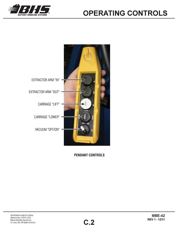
The MBE is maneuvered by the operator from the rear of the unit using the powerhead controls. Battery extraction is controlled by the operator via a control pendant that would typically be standing next to the MBE. The MBE is constructed of a steel frame, which houses a fully enclosed, self contained, electrically powered, hydraulic power unit located at the rear of the inside frame. The power unit provides power to raise the inside frame using a hydraulic cylinder and power to move the extractor arm inward and outward using a hydraulic motor. The lift and extraction functions are controlled by an electrical control pendant located at the left, rear of the unit. The unit is equipped with vacuum extraction which has a vacuum pump located at the rear of the inside frame. The vacuum is controlled by an on/off switch on the control pendant.
Where possible, images are of the latest powerhead configuration. Images shown may differ slightly from actual units based on the manufacture date.
GENERAL SAFETY
- Read and understand all instructions and warnings before using or servicing this equipment.
- Keep these instructions for future reference.
- Refer to the powerhead manual(s) for proper operation and service procedures before performing any service or maintenance to the powerhead and/or Mobile Battery Extractor (MBE) unit.
- MBE units shall only be used indoors in an industrial setting on a hard, nonslip, and level floor without defects including but not limited to holes, gouges, cracks, drains or obstacles comprised of concrete or other suitable industrial material.
- Forces required to operate the MBE vary with weight of the load, floor conditions, and carriage conditions.
- MBE units are not designed to be shipped or transported after initial delivery.
- A licensed structural engineer should be consulted prior to installing an MBE on any building level other than the ground floor.
- Perform system and safety check before operating.
- Failure to follow these instructions and warnings may result in property damage, personal injury or death.
WORK AREA
- Keep work area clean and well lit. Cluttered work areas and poor lighting can lead to accidents.
- Clean up/contain any fluid spills immediately to prevent slips or falls.
- Be aware of potential hazards when performing any service or maintenance to the unit.
SERVICE & MAINTENANCE
Service personnel shall wear Personal Protective Equipment (PPE) appropriate for the task being performed.
LOCKOUT/TAGOUT
Lockout/tagout the BWC per your corporate policy, if damaged or not functioning properly. Lockout/tagout and deenergize all systems prior to performing any maintenance or service to unit.
LEAD-ACID BATTERIES-EXPLOSION HAZARD
Do not allow open flames or sparks of any kind near a battery. Highly explosive gas is generated when charging a battery that can remain in battery cells for extended periods of time after charging is complete.
- Always wear appropriate PPE including rubber apron, gloves, boots and full face shield when performing service or maintenance to any lead-acid batteries.
- Do not place metal or other conductive objects on top of battery. Arcing may occur causing damage to the battery and/or serious personal injury or death.
- Use only chargers matching the voltage and amperage of the battery being charged. Overcharging a battery can cause damage to the battery, charger and/or serious personal injury or death.
- Turn off charger before disconnecting battery from charger. Arcing between battery and charger connectors can cause damage to the connectors and/or serious personal injury or death.
BATTERY WASH WATER HAZARDS
HYDRAULIC HAZARD
AVOID HIGH PRESSURE FLUIDS-Escaping fluid under pressure can penetrate the skin causing serious injury. Relieve pressure before disconnecting hydraulic lines. Tighten all connections before applying pressure. Keep hands and body away from pin holes which eject fluids under high pressure. Use a piece of cardboard or paper to search for leaks. DO NOT use your hand.
Any fluid injected into the skin under high pressure should be considered a serious medical emergency despite an initial normal appearance of the skin. There will be a delayed onset of pain, and serious tissue damage may occur. Medical attention should be sought immediately.
OPERATIONAL SAFETY
OPERATIONAL SAFETY
- Only personnel trained in the proper and safe operation of MBE units may operate or service the MBE.
- Operators shall wear appropriate PPE suitable for working with industrial lead-acid batteries while operating the MBE (see prior page)
- All data plates, warning labels, placards, etc. shall be in place and legible at all times. Contact BHS for replacement data plates, warning labels, placards or instructions.
- All users and service personnel shall be familiar with the meaning and risks associated with all data plates, warning labels, etc.
- All operators and service personnel shall be aware of potential crush and shear points while operating or servicing the MBE.
- Keep hands and arms out of the battery compartment while operating the MBE.
- MBE shall be operated in an area with ambient light levels of at least 50 lux.
- Engage the battery safety bar and properly secure the battery prior to transporting the battery.
- Avoid abrupt changes in direction when transporting a battery in the MBE to prevent loss of the battery and/or loss of control of the MBE.
- Remove MBE from service if damaged, defective, or operating improperly (or becomes such while operating) until repairs can be made to correct any problem(s).
DO’s AND DON’T’s
- DO NOT exceed the maximum capacity of MBE.
- DO NOT modify or fit the MBE with attachments without prior, written approval from BHS.
- DO NOT perform any maintenance or service to the powerhead or MBE with a battery loaded on the MBE.
- DO NOT allow anyone to ride in or on the MBE.
- DO NOT operate the MBE with any guard or cover removed unless required for maintenance or repair.
- DO NOT travel with the stop bar in the raised position.
- DO NOT lower the inside frame on any person or object.
- Disconnect the electrical connection between the MBE and the powerhead prior to charging the powerhead battery.
- Disconnect the MBE from all power sources and engage the e-stop before attempting to perform service or maintenance to the unit.
- DO NOT use the MBE in a manner for which it is not intended. Some examples of prohibited use are but not limited to:
- As a scooter or to transport people
- As a vehicle jack
- To lift loads greater than its rated load capacity
- Where unintentional movement may exist
- Having direct contact with foodstuff
- In a potentially explosive atmosphere
DE-ENERGIZATION
The following procedure DOES NOT de-energize the powerhead of the MBE - only the lift and extraction function/ of the MBE - only the lift and extraction function/ components of the unit. Refer to the powerhead manufacturers components of the unit. Refer to the powerhead manufacturers manual(s) for proper servicing procedures.
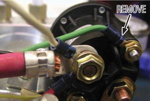
- Remove the green wire from the small, positive terminal of the solenoid. Secure the green solenoid wire so it cannot contact any other terminals, ground points, or metal parts. See Figure 1.
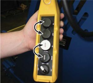
- Depress the IN, OUT, UP, and DOWN buttons of the pendant to relieve any stored hydraulic pressure. See Figure 2.
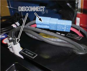
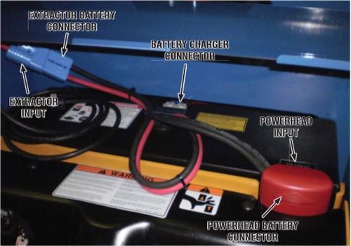
- Disconnect the DC power supply by unplugging/disconnecting the power connector/leads to the powerhead battery. See Figure 3.
FIGURE 1
FIGURE 2
FIGURE 3
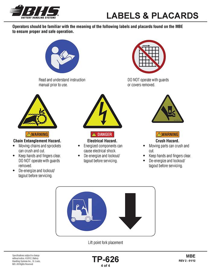
LABELS & PLACARDS
GENERAL INFORMATION
SPECIFICATIONS
Product Specifications - Imperial / Metric | MBE-42 | MBE-42-5 |
Max. Load Capacity | 4,000 lbs / 1814 kg | 5,000 lbs / 2268 kg |
Operating Voltage | 24 VDC | 24 VDC |
Hydraulic Pump Type | Gear, Fixed Displacement | Gear, Fixed Displacement |
Pump | 1.3 GPM / 4.9 LPM | 1.3 GPM / 4.9 LPM |
Raise / Lower Speed* (maximum) | 8.8 FPM / 9.4 FPM .044 m/s / .048 m/s | 8.8 FPM / 9.4 FPM .044 m/s / .048 m/s |
Battery Attachment | Vacuum | Vacuum |
Vacuum Cup | 12" / 305 mm Dia. | 12" / 305 mm Dia. |
Vacuum | 21" Hg / .73 kg/cm2 | 21" Hg / .73 kg/cm2 |
Primary Drive Chain Size | #50 | #50 |
Rated Draw Bar Pull | 1125 lbs / 510 kg | 1125 lbs / 510 kg |
Roller Diameter | 2.4" / 61 mm | 2.4" / 61 mm |
Roller Shaft Size | .75" / 19 mm Hex | .75" / 19 mm Hex |
Battery Width | 13" Min / 41" Max 330 mm Min / 1041 mm Max | 13" Min / 41" Max 330 mm Min / 1041 mm Max |
Battery Length | 18" Min / 49" Max 457 mm Min / 1244 mm Max | 18" Min / 49" Max 457 mm Min / 1244 mm Max |
Battery Height | 21" Min / 32.5" Max 533 mm Min / 825 mm Max | 21" Min / 32.5" Max 533 mm Min / 825 mm Max |
Overall Dimensions (L x W x H) | 108" x 63.5" x 79.5" 2743 mm x 1613 mm x 2019 mm | 119" x 63.5" x 79.5" 3023 mm x 1613 mm x 2019 mm |
Slide Strip Length | 23.5" / 597 mm | 23.5" / 597 mm |
Roller Width | 41.875" / 1064 mm | 41.875" / 1064 mm |
Extended Arm Reach (Beyond Roller Bed) | 10.5" / 267 mm | 10.5" / 267 mm |
Extractor Arm Travel Speed | 22 FPM / .11 m/s | 22 FPM / .11 m/s |
Service Weight (unloaded) | 3650 lbs / 1655 kg | 3840 lbs / 1742 kg |
Turning Radius | 8' / 2.4 m | 9' / 2.75 m |
Min. Service Aisle | 16' / 4.8 m | 17' / 5.2 m |
Battery Compartment Depth | 49" / 1245 mm | 49" / 1245 mm |
Battery Compartment Width | 42” / 1067 mm | 42” / 1067 mm |
Wheelbase | 80" / 2032 mm | 93.5" / 2375 mm |
Ground Clearance (Inside Frame Elevated 1”) | .75" / 19 mm (Outside Frame Fixed) | .75" / 19 mm (Outside Frame Fixed) |
Grade Clearance | 2% | 2% |
Floor to Roller Height | 3.5" Min / 33.5" Max 89 mm Min / 851 mm Max | 3.5" Min / 33.5" Max 89 mm Min / 851 mm Max |
Max Travel Speed* | 155 FPM / .787 m/s Loaded 200 FPM / 1.016 m/s Unloaded | 155 FPM / .787 m/s Loaded 200 FPM / 1.016 m/s Unloaded |
Controls | 5 Button Side Mounted Tethered Pendant | 5 Button Side Mounted Tethered Pendant |
- Speeds will vary based on loading conditions and charge state of battery
UNPACKING
The following instructions will guide you through the basic steps necessary to remove the MBE from its shipping skid.
- Position the MBE in an area allowing ample space to position a lift truck on each side of the MBE.
- Carefully remove any shrink wrap, then cut and remove all banding material securing the MBE to the shipping skid.
- Adjust the forks of the lift trucks to be used to lift the MBE to their widest positions.
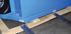
- Position the forks of the lift trucks directly under the arrows of the "lift point fork placement" labels on both sides of the MBE. See Figure 2.
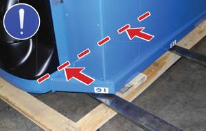
- Slowly insert the forks approximately 12" under the MBE frame. See Figure 3
- Once the forks of both lift trucks are properly positioned under the MBE, SLOWLY raise the forks of both trucks simultaneously to lift the MBE from the skid.
- Raise the MBE until the drive wheel clears the skid and remove the skid from under the MBE.
- SLOWY lower the MBE to the floor.
- Lower the forks to the floor, remove the forks from under the MBE, and exit the lift trucks from the area.
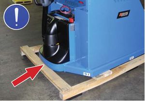
The MBE drive wheel sets below the shipping skid cross boards. Use care not to damage the drive wheel when handling the unit from the operator end. See Figure 1.
FIGURE 1
FIGURE 2
The MBE drive wheel sets below the shipping skid cross boards. Use care not to damage the drive wheel when handling the unit from the operator end. See Figure 1.
FIGURE 3
OPERATING CONTROLS
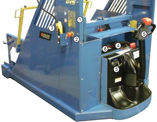
SERIAL NUMBER / DATA TAGS Lists Model and Serial Number of unit.
EMERGENCY STOP Disconnects all electrical power to extractor portion of unit.
CONTROL PENDANT Controls extractor arm movement in and out of battery compartment, lift/lower of battery compartment, and vacuum off/on.
D.C. POWER CABLES Main power cables supplying power from powerhead battery to extractor and powerhead.
POWERHEAD CONTROLS Controls powerhead functions.
Refer to powerhead manual(s) for operating controls and instructions.
BATTERY CHARGER CORD Built-in 110V AC charger for charging powerhead battery.
D.C. CABLE CONNECTIONS
The following instructions will guide you through the basic steps necessary to charge the powerhead battery. Refer to the powerhead manual for complete instructions, warnings and safety procedures.
1. Disconnect the Extractor Input and Extractor Battery connectors.
DO NOT charge the powerhead battery with the Extractor Input connected. Damage to extractor components may occur.
2. Disconnect the Powerhead Battery connector from the Powerhead input labeled "TO DRIVE" and connect it to the Battery Charger connector labeled "TO CHARGE".
3. Plug the battery charger cord into a 110V outlet.
OPERATING INSTRUCTIONS
The following instructions will guide you through the basic steps necessary to operate and change batteries with an MBE.
Operators must be equipped with all necessary PPE and be properly trained in handling industrial lead-acid lift truck batteries.
- If not already in place, position industrial truck (pallet or lift truck) which requires a battery change in the appropriate staging area.
- Disconnect the battery leads and remove any battery restraints.
- Move the MBE into position such that the battery compartment of the industrial truck is aligned with the roller compartment of the MBE.
- Raise the battery safety stop.
- Depress the "up" or "down" button on the control pendant to adjust the vertical height of the MBE battery compartment. Adjust the height of the MBE battery compartment with the battery compartment of the industrial truck or slightly higher. DO NOT exceed 1/4" difference.
- Depress the “out" button to extend the extractor arm toward the battery.
- Release the button once the vacuum cup has made contact with the battery.
- Energize the vacuum by turning the switch on the control pendant "on".
- Depress the "in" button to begin removing the battery from the industrial truck battery compartment while inspecting the vertical alignment of both battery compartments. If vertical adjustment is needed, disengage the vacuum cup prior to adjusting the height of the MBE.
- Once the battery is entirely inside the MBE battery compartment, carefully lower the battery safety stop. Turn off the vacuum.
- The battery may now be transported to the charging area.
- Align the MBE with an open roller compartment in the battery charging area. Be sure to check the vertical alignment of the two roller compartments.
- Raise the MBE battery safety stop. Lower the battery safety stop on the battery roller stand.
- Depress the "out" button to move the battery in to the empty roller compartment.
- Raise the battery safety stop on the battery roller stand and connect the battery to the appropriate charger.
- Locate and remove a fully charged battery to be installed into the industrial truck by following the above process.
DO NOT force the cup into the battery after initial contact with the battery is made.
DO NOT force the cup/magnet into the battery after the battery contacts the backstop.
ALWAYS be sure charging has been completed and the charger is not still charging the battery. Dangerous sparking/arcing can occur if the battery is unplugged from the charger while charging.
Many batteries are a tight fi t into the lift truck battery compartments. Care MUST be taken to ensure alignment is precise to avoid damage to the battery, lift truck, and/or battery extractor.
MANUAL UNLOADING
Lockout/tagout and de-energize all equipment prior to manually unloading any battery.
Manual unloading of the MBE is not recommended. In the event of power loss or an operational malfunction of the MBE not allowing a battery to be unloaded using normal operating procedures, only repairs required to safely maneuver the MBE to a position allowing safe unloading using normal operating procedures should be made. Once any batteries are safely unloaded, any remaining repairs can be made.
Extreme care should be taken when working under or around equipment supporting elevated loads. Unexpected movement of the equipment could cause the load and/or equipment to fall. ALWAYS be sure devices of adequate size and strength are in place to prevent any personnel working under the elevated load from being crushed. Serious personal injury or death will occur.
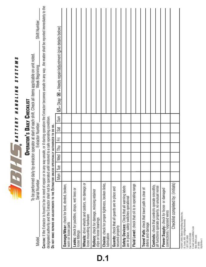
OPERATOR’S DAILY CHECKLIST
PARTS SECTIONS
CHASSIS
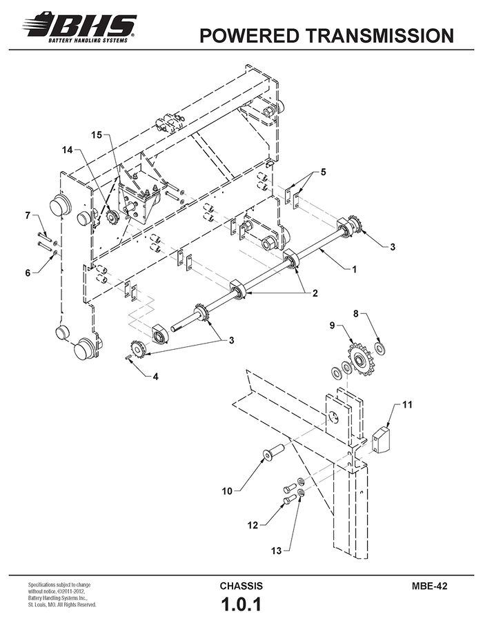
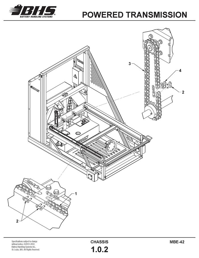
POWERED TRANSMISSION
ITEM | BHS PART NUMBER | DESCRIPTION | REF. KIT NO. | NOTES | NO. REQ |
1 | 35027001 | SHAFT-ARM DRIVE | 1 | ||
2 | PT0402 | BEARING-PILLOW BLOCK-1" | 4 | ||
3 | PT0107 | SPROCKET-5015 X 1" | INCLUDES SET SCREWS | 3 | |
4 | 00197028 | KEY-1/4" X 1 1/4" | 3 | ||
5 | 08027002 | SHIM-PILLOW BLOCK-THIN | .075" THICK | A/R | |
08027003 | SHIM-PILLOW BLOCK-THICK | .135" THICK | A/R | ||
6 | HW0108 | WASHER-FLAT-3/8"-SAE | 8 | ||
7 | HW0407 | BOLT-HHCS-3/8-16 X 2 3/4" | 8 | ||
8 | HW0114 | WASHER-FLAT-5/8"-SAE | 6 | ||
9 | PT0111 | SPROCKET-IDLER-501A5 X 5/8" | 2 | ||
10 | HW0603 | BOLT-FHSCS-5/8-11 X 2" | 2 | ||
11 | 05517033 | STOP-EXTRACTOR ARM | 2 | ||
12 | HW0402 | BOLT-HHCS-3/8-16 X 1" | 4 | ||
13 | HW0107 | WASHER-LOCK-3/8" | 4 | ||
14 | PT0106-1 | SPROCKET-5012 X 1" | INCLUDES SET SCREWS | 1 | |
15 | HW1071 | KEY-WOODRUFF-#808 STANDARD | SUPPLIED WITH MOTOR | 1 |
ITEM | BHS PART NUMBER | DESCRIPTION | REF. KIT NO. | NOTES | NO. REQ |
1 | 00158001-35 | CHAIN-ROLLER-#50 | EXTRACTOR ARM | 2 | |
2 | PT0102 | CONNECTING LINK-#50 | 5 | ||
3 | 00158001-34 | CHAIN-ROLLER-#50 | DRIVE MOTOR | 1 | |
4 | PT0104 | LINK-OFFSET-#50 | 1 |
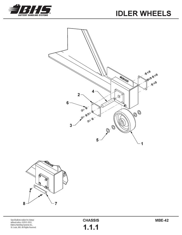
IDLER WHEELS
ITEM | BHS PART NUMBER | DESCRIPTION | REF. KIT NO. | NOTES | NO. REQ |
1 | C0601 | WHEEL-POLY-8" X 3" | 2 | ||
2 | 35017038 | PLATE-RETAINING | 4 | ||
3 | HW0401 | BOLT-HHCS-3/8-16 X 3/4" | 16 | ||
4 | 35017039 | SHAFT-IDLER WHEEL | 2 | ||
5 | HW0147 | WASHER-SHIM-1/8" | † SEE NOTES | A/R | |
HW0148 | WASHER-SHIM-1/16" | A/R | |||
HW0127 | WASHER-SHIM-.165" | A/R | |||
6 | HW0107 | WASHER-LOCK-3/8" | 16 | ||
7 | 35017080 | PLATE-ACCESS COVER | 2 | ||
8 | HW0301 | BOLT-SELF-TAP “F”-1/4-20 X 1/2" | 4 |
†WASHER THICKNESS AND QUANTITY CAN VARY BETWEEN MACHINES DUE TO MANUFACTURING TOLERANCES. MEASURE WASHER THICKNESS AND DETERMINE QUANTITY NEEDED PRIOR TO ORDERING.
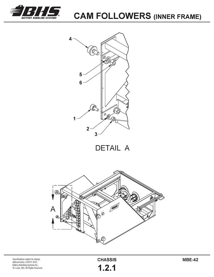
CAM FOLLOWERS (INNER FRAME)
ITEM | BHS PART NUMBER | DESCRIPTION | REF. KIT NO. | NOTES | NO. REQ |
1 | PT0505 | BEARING-FLANGED LOAD-2 1/4" | 4 | ||
2 | HW0117 | WASHER-LOCK-7/8" | 4 | ||
3 | HW0025 | NUT-JAM-7/8-14 | 4 | ||
4 | PT0507 | CAM ROLLER-3" | 4 | ||
5 | HW0142 | WASHER-LOCK-1 1/4" | 4 | ||
6 | HW0141 | NUT-HEX-1 1/4-12 | 4 |
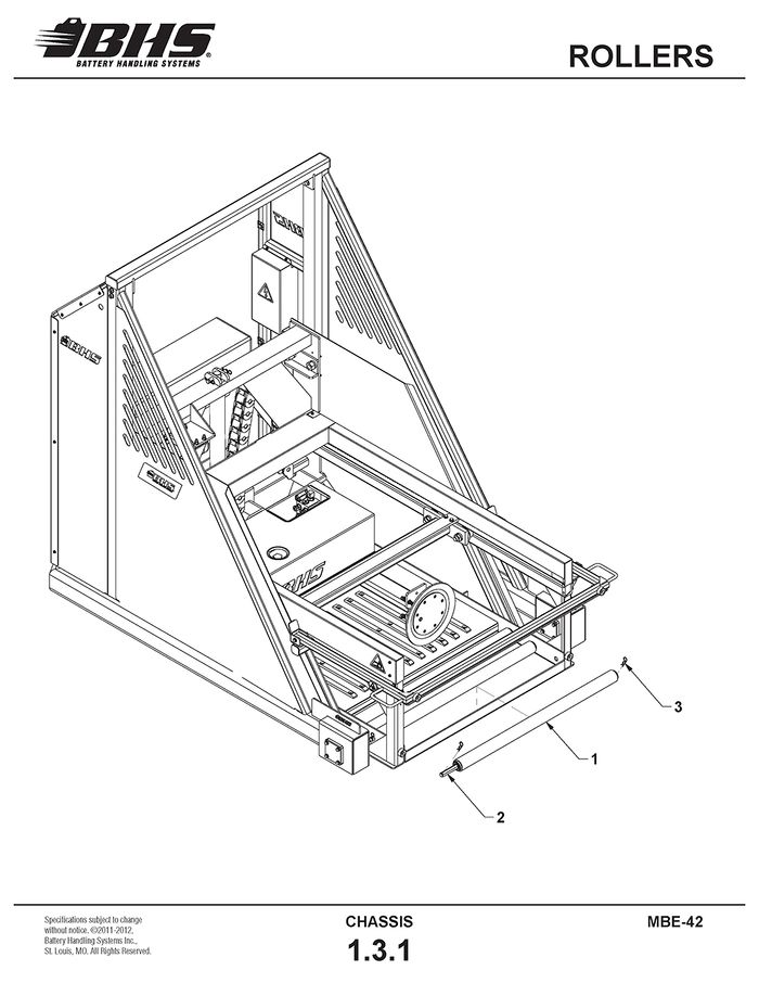
ROLLERS
ITEM | BHS PART NUMBER | DESCRIPTION | REF. KIT NO. | NOTES | NO. REQ |
1 | 43482002 | ROLLER ASSEMBLY | 3 | ||
2 | 43487002 | SHAFT-HEX-.75" X 43.75" | 3 | ||
3 | HW1058 | PIN-HITCH | 6 |
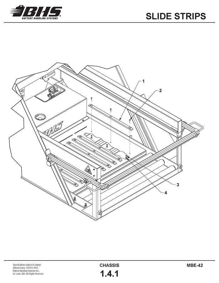
SLIDE STRIPS
ITEM | BHS PART NUMBER | DESCRIPTION | REF. KIT NO. | NOTES | NO. REQ |
1 | 35017021 | STRIP-SLIDE | (QTY. OF 11 WITH DUAL CUP OPTION) | 9 | |
2 | HW0306 | BOLT-FHSCS-1/4-20 X 1" | (QTY. OF 33 WITH DUAL CUP OPTION) † SEE NOTES | 27 | |
3 | HW0103 | WASHER-LOCK-1/4" | 27 | ||
4 | HW0002 | NUT-HEX-1/4-20 | 27 |
†WASHERS AND NUTS REQ'D ON UNITS BUILT PRIOR TO JANUARY, 2011
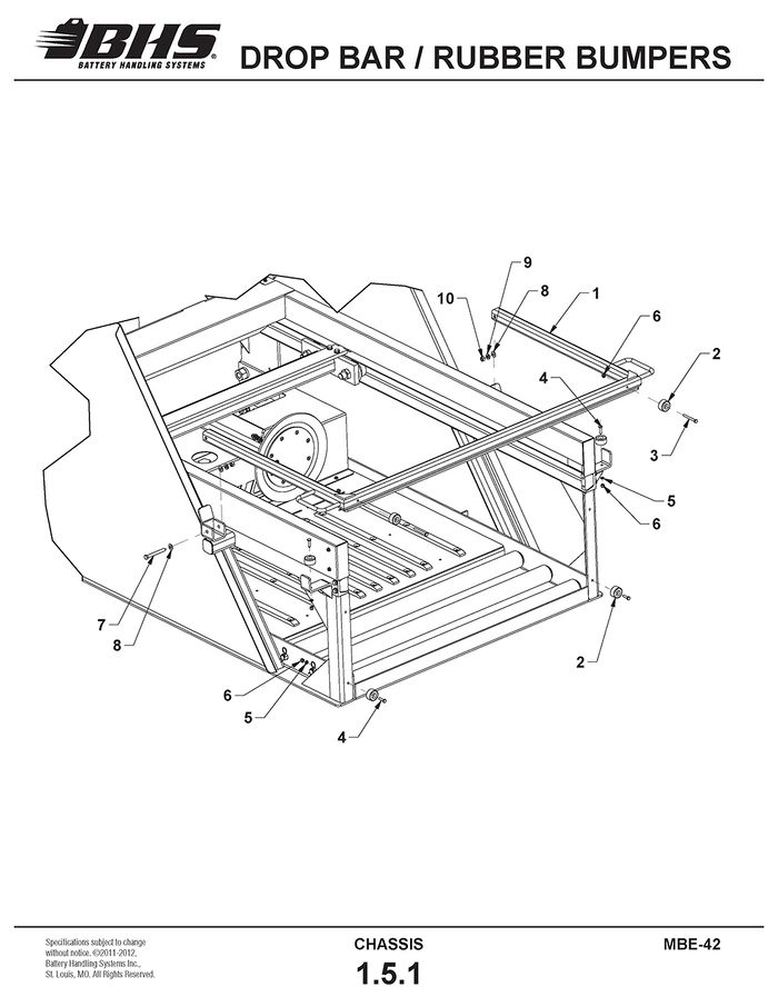
DROP BAR / RUBBER BUMPERS
ITEM | BHS PART NUMBER | DESCRIPTION | REF. KIT NO. | NOTES | NO. REQ |
1 | 35015007 | DROP BAR | 1 | ||
2 | HW1037 | BUMPER-RUBBER | 80092001 | 6 | |
3 | HW0308 | BOLT-HHCS-1/4-20 X 2 1/2" | 2 | ||
4 | HW0303 | BOLT-HHCS-1/4-20 X 1" | 80092001 | 4 | |
5 | HW0104 | WASHER-FLAT-1/4"-SAE | 80092001 | 6 | |
6 | HW0003 | NUT-NILN-1/4-20 | 6 | ||
7 | HW0408 | BOLT-HHCS-3/8-16 X 3 1/4" | 2 | ||
8 | HW0108 | WASHER-FLAT-3/8"-SAE | 4 | ||
9 | HW0107 | WASHER-LOCK-3/8" | 2 | ||
10 | HW0005 | NUT-HEX-3/8-16 | 2 |
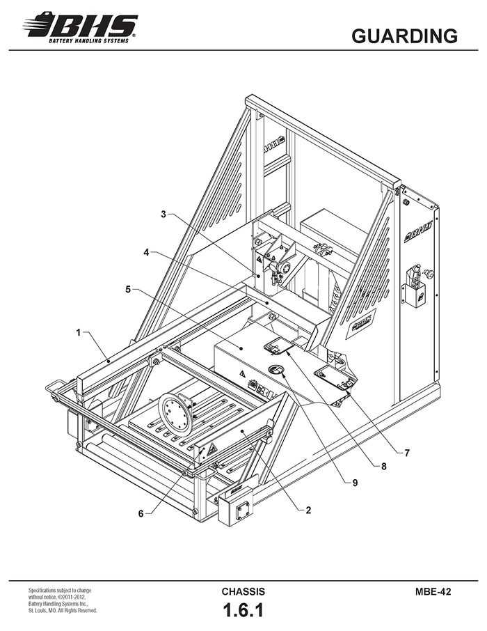
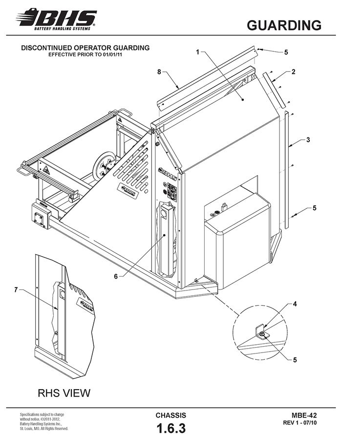
GUARDING
ITEM | BHS PART NUMBER | DESCRIPTION | REF. KIT NO. | NOTES | NO. REQ |
1 | 35017035-4 | GUARD-CHAIN-RHS | 1 | ||
2 | 35017035-3 | GUARD-CHAIN-LHS | 1 | ||
3 | 35015008 | GUARD-CHAIN-ARM DRIVE | 1 | ||
4 | 35017069-2 | GUARD-DRIVE SHAFT | 1 | ||
5 | 35017062-2 | GUARD-COMPONENT | 1 | ||
6 | HW0301 | BOLT-SELF-TAP “F”-1/4-20 X 1/2" | GUARD MOUNTING BOLTS | 16 | |
7 | PL0602 | VINYL EDGING | SOLD BY LENGTH | 12" | |
8 | PL0602 | VINYL EDGING | SOLD BY LENGTH | 18" | |
9 | PL0602 | VINYL EDGING | SOLD BY LENGTH | 22" |
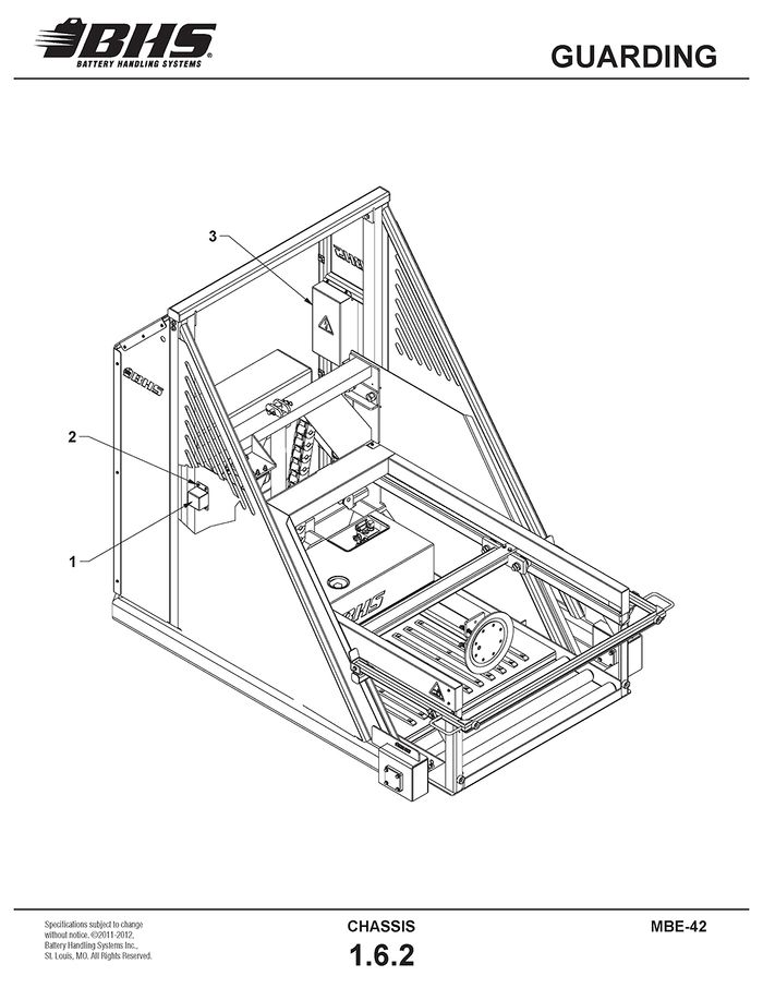
ITEM | BHS PART NUMBER | DESCRIPTION | REF. KIT NO. | NOTES | NO. REQ |
1 | 35017052-2 | GUARD-CAM FOLLOWER | 2 | ||
2 | HW0301 | BOLT-SELF-TAP “F”-1/4-20 X 1" | GUARD MOUNTING BOLTS | 13 | |
3 | 35017073-2 | COVER-EMERGENCY STOP | UNITS BUILT PRIOR TO 01/01/11 | 1 | |
35017085-2 | COVER-EMERGENCY STOP | UNITS BUILT 01/01/11 TO PRES. | 1 |
ITEM | BHS PART NUMBER | DESCRIPTION | REF. KIT NO. | NOTES | NO. REQ |
1 | 35005001 | GUARD-OPERATOR | USED ONLY ON UNITS BUILT PRIOR TO 01/01/11 | 1 | |
2 | 35017074-2 | SUPPORT-OPERATOR GUARD-UPPER | 2 | ||
3 | 35017061-2 | SUPPORT-OPERATOR GUARD-LOWER | 2 | ||
4 | 43018004-2 | TAB-MOUNTING | 2 | ||
5 | HW0301 | BOLT-SELF TAP “F”-1/4-20 X 1/2 | GUARD MOUNTING BOLTS | 24 | |
6 | 35017058-3 | GUARD-REAR-CAM FOLLOWER-LHS | 1 | ||
7 | 35017058-4 | GUARD-REAR-CAM FOLLOWER-RHS | 1 | ||
8 | 35017081-2 | CROSS SUPPORT-OPERATOR GUARD | 1 |
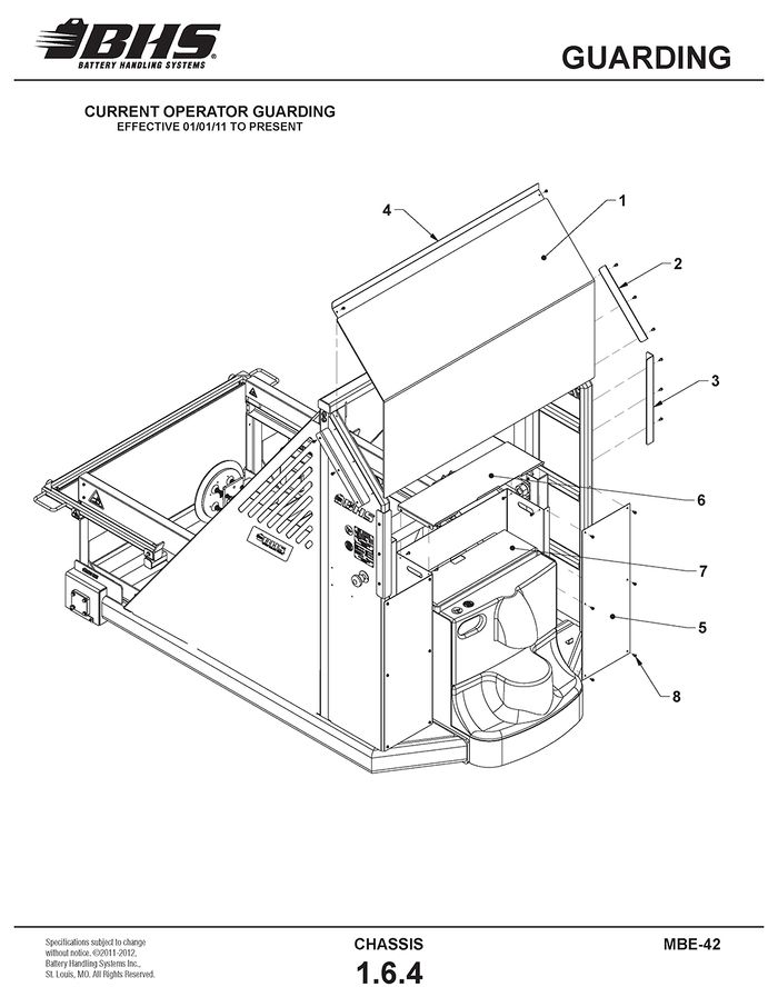
ITEM | BHS PART NUMBER | DESCRIPTION | REF. KIT NO. | NOTES | NO. REQ |
1 | 35004004 | GUARD-OPERATOR | 1 | ||
2 | 35017074-2 | SUPPORT-OPERATOR GUARD-UPPER | 2 | ||
3 | 35017090-2 | SUPPORT-OPERATOR GUARD-LOWER | 2 | ||
4 | 35017081-2 | CROSS SUPPORT-OPERATOR GUARD | 1 | ||
5 | 35017088 | GUARD-OPERATOR-LOWER | 2 | ||
6 | 35017089-2 | GUARD-TOP-BATTERY BOX | 1 | ||
7 | 35017087-2 | GUARD-BATTERY BOX | 1 | ||
8 | HW0301 | BOLT-SELF TAP “F”-1/4-20 X 1/2 | GUARD MOUNTING BOLTS | 34 |
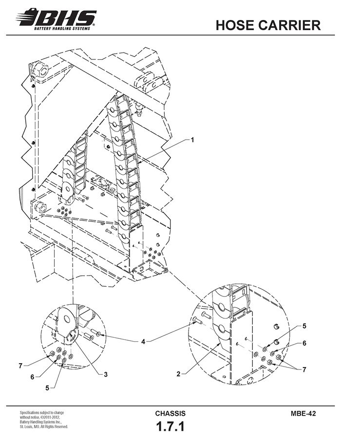
HOSE CARRIER
ITEM | BHS PART NUMBER | DESCRIPTION | REF. KIT NO. | NOTES | NO. REQ |
1 | PT0627 | HOSE CARRIER | 21 LINKS REQD | 59" | |
2 | PT0628 | BRACKET-END-MALE | SOLD AS SET | 1 | |
3 | BRACKET-END-FEMALE | 1 | |||
4 | HW0306 | BOLT-FHSCS-1/4-20 X 1" | 4 | ||
5 | HW0104 | WASHER-FLAT-1/4"-SAE | 4 | ||
6 | HW0103 | WASHER-LOCK-1/4" | 4 | ||
7 | HW0002 | NUT-HEX-1/4-20 | 4 |
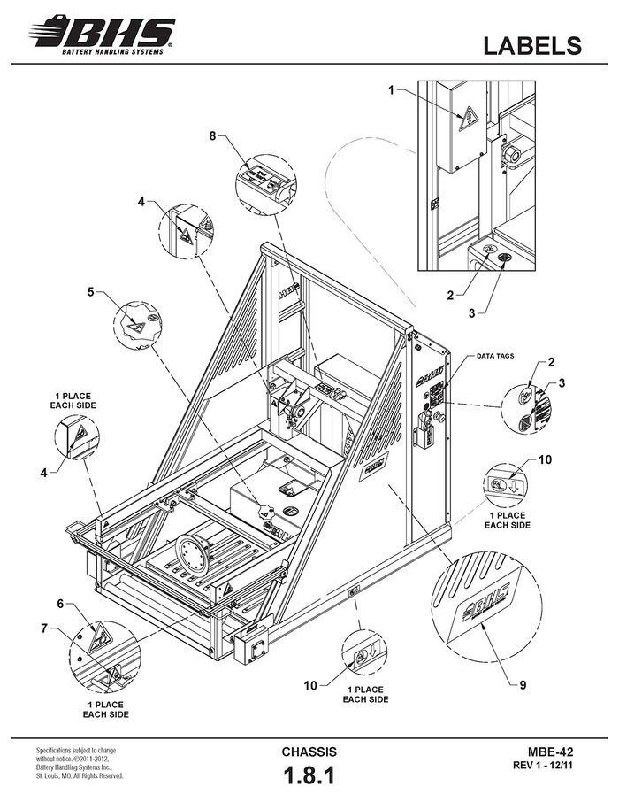
LABELS
ITEM | BHS PART NUMBER | DESCRIPTION | REF. KIT NO. | NOTES | NO. REQ |
1 | 00196219 | LABEL-WARNING-"ELECTRICAL VOLTAGE HAZARD" | LARGE | 1 | |
2 | 00196612 | LABEL-"READ INSTRUCTION MANUAL PRIOR TO USE" | 2 | ||
3 | 00196615 | LABEL-"DO NOT OPERATE WITH GUARDS REMOVED" | 2 | ||
4 | 00196215 | LABEL-WARNING-"CHAIN ENTANGLEMENT HAZARD" | SMALL | 3 | |
5 | 00196218 | LABEL-WARNING-"ELECTRICAL VOLTAGE HAZARD" | SMALL | 1 | |
6 | 00196216 | LABEL-WARNING-"CHAIN ENTANGLEMENT HAZARD" | LARGE | 2 | |
7 | 00196222 | LABEL-WARNING-"CRUSH HAZARD" | 2 | ||
8 | 00196726 | LABEL-CAPACITY-"5,000 LBS MAX" | 1 | ||
9 | 00196701 | DECAL-BHS-12" X 3.875" | 2 | ||
10 | 00196622 | LABEL-LIFT POINT FORK PLACEMENT | 4 |
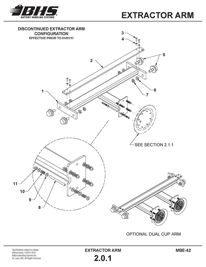
EXTRACTOR ARM
STANDARD EXTRACTOR ARM
ITEM | BHS PART NUMBER | DESCRIPTION | REF. KIT NO. | NOTES | NO. REQ |
1 | 35055001 | EXTRACTOR ARM | STANDARD | 1 | |
35055002 | EXTRACTOR ARM-DUAL CUP | OPTIONAL | 1 | ||
2 | 35017019 | BAR-CROSS | USED PRIOR TO 01/01/11 | 1 | |
3 | HW0425 | BOLT-HHCS-3/8-16 X 1 1/4" | 4 | ||
4 | HW0107 | WASHER-LOCK-3/8" | 4 | ||
5 | 43026001 | BEARING-FLANGED LOAD-2 1/4" | 4 | ||
6 | HW0117 | WASHER-LOCK-7/8" | 4 | ||
7 | HW0025 | NUT-JAM-7/8-14 | 4 | ||
8 | HW0428 | STUD-VACUUM-3/8-16 X 5" | HW-KIT-2 | QTY. REQ'D PER VACUUM CUP | 4 |
9 | HW0108 | WASHER-FLAT-3/8"-SAE | HW-KIT-2 | QTY. REQ'D PER VACUUM CUP | 20 |
10 | HW1001 | SPRING-3/8" | HW-KIT-2 | QTY. REQ'D PER VACUUM CUP | 12 |
11 | HW0006 | NUT-NILN-3/8-16 | HW-KIT-2 | QTY. REQ'D PER VACUUM CUP | 4 |
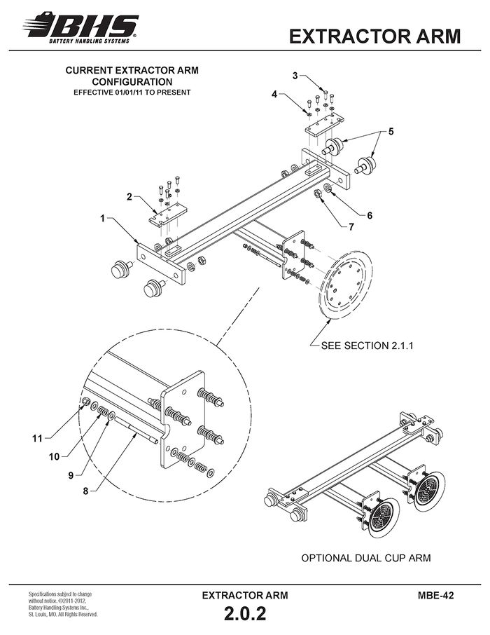
ITEM | BHS PART NUMBER | DESCRIPTION | REF. KIT NO. | NOTES | NO. REQ |
1 | 35055001 | EXTRACTOR ARM | STANDARD | 1 | |
35055002 | EXTRACTOR ARM-DUAL CUP | OPTIONAL | 1 | ||
2 | 35037002 | PLATE-CHAIN ATTACHMENT | USED 01/01/11 TO PRESENT | 2 | |
3 | HW0425 | BOLT-HHCS-3/8-16 X 1 1/4" | 8 | ||
4 | HW0107 | WASHER-LOCK-3/8" | 8 | ||
5 | 43026001 | BEARING-FLANGED LOAD-2 1/4" | 4 | ||
6 | HW0117 | WASHER-LOCK-7/8" | 4 | ||
7 | HW0025 | NUT-JAM-7/8-14 | 4 | ||
8 | HW0428 | STUD-VACUUM-3/8-16 X 5" | HW-KIT-2 | QTY. REQ'D PER VACUUM CUP | 4 |
9 | HW0108 | WASHER-FLAT-3/8"-SAE | HW-KIT-2 | QTY. REQ'D PER VACUUM CUP | 20 |
10 | HW1001 | SPRING-3/8" | HW-KIT-2 | QTY. REQ'D PER VACUUM CUP | 12 |
11 | HW0006 | NUT-NILN-3/8-16 | HW-KIT-2 | QTY. REQ'D PER VACUUM CUP | 4 |
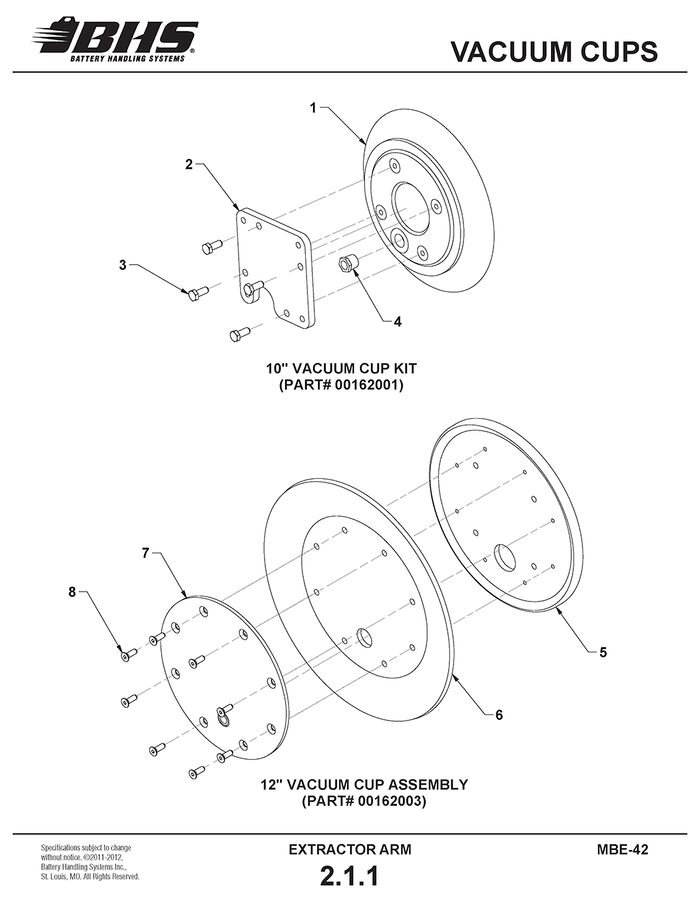
VACUUM CUPS
ITEM | BHS PART NUMBER | DESCRIPTION | REF. KIT NO. | NOTES | NO. REQ |
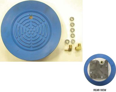
1 | N/A | VACUUM CUP-10" ROUND | 00162001 | † SOLD IN KIT ONLY | 1 |
2 | 00117059 | PLATE-VACUUM CUP ADAPTER | 00162001 | 1 | |
3 | HW0328 | BOLT-HHCS-5/16-18 X 3/4" | 00162001 | 4 | |
4 | P0505 | BUSHING-RED-#6 NPT X #4 NPTF-BRASS | 00162001 | 1 | |
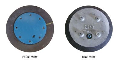
5 | 00166001 | CASTING-12" VACUUM CUP | 00162003 | 1 | |
6 | 00164001 | SEAL-RUBBER | 00162003 | 1 | |
7 | 00165001 | PLATE-FRONT | 00162003 | 1 | |
8 | HW0311 | BOLT-FHSCS-1/4-20 X 5/8" | 00162003 | 8 |
† ONE-PIECE CONSTRUCTION
PNEUMATICS
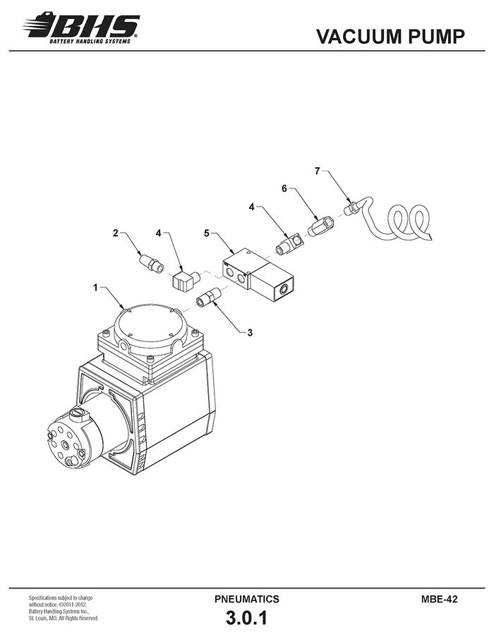
VACUUM PUMP
ITEM | BHS PART NUMBER | DESCRIPTION | REF. KIT NO. | NOTES | NO. REQ |
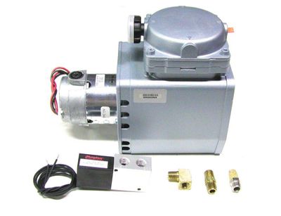
1 | P0002 | VACUUM PUMP-24VDC | 80062002 | 1 | |
2 | P0208 | FILTER-HIGH FLOW | 80062002 | 2 | |
3 | P0503 | NIPPLE-#4 NPT-BRASS | 80062002 | 1 | |
4 | P0506 | ELBOW-STR-90 DEG-#4 NPT-BRASS | 80062002 | 2 | |
5 | P0206 | VALVE-VACUUM RELEASE-24VDC | 80062002 | 1 | |
6 | P0111 | FILTER-VACUUM-IN LINE | 80062002 | 1 | |
7 | P0301-1 | HOSE-COIL-VACUUM | 1 | ||
8 | HW0212 | SCREW-RHMS-#10-24 X 1/2" | PUMP MOUNTING HARDWARE (NOT SHOWN) | 4 | |
9 | HW0101 | WASHER-LOCK-#10 | 4 |
HYDRAULICS
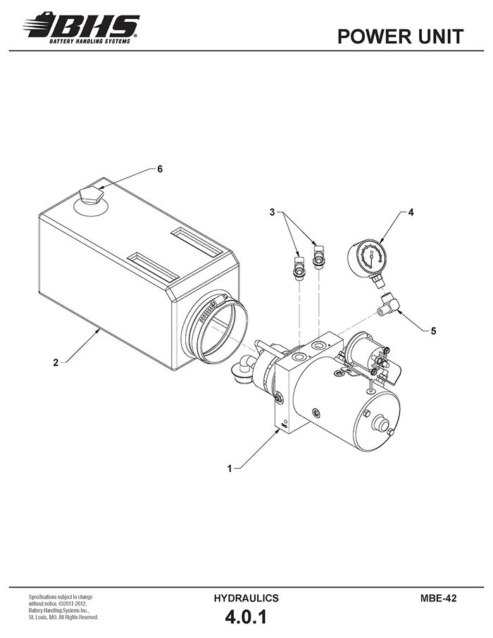
POWER UNIT
ITEM | BHS PART NUMBER | DESCRIPTION | REF. KIT NO. | NOTES | NO. REQ |
1 | HC0004-4 | POWER UNIT ASSEMBLY-24VDC | DOES NOT INCLUDE RESERVOIR | 1 | |
2 | 14168 | RESERVOIR | 1 | ||
3 | H1615 | ELBOW-90 DEG-#6 JICM X #6 SAEM | 2 | ||
4 | HC0318 | GUAGE-PRESSURE | INCL. WITH POWER UNIT | 1 | |
5 | H0300 | ELBOW-STR-90 DEG-#4 NPT | 1 | ||
6 | HC0238 | CAP-RESERVOIR | 1 | ||
7 | HW0401 | BOLT-HHCS-3/8-16 X 3/4" | MOUNTING HARDWARE (NOT SHOWN) | 2 | |
8 | HW0107 | WASHER-LOCK-3/8" | 2 | ||
9 | HW0108 | WASHER-FLAT-3/8"-SAE | 2 |
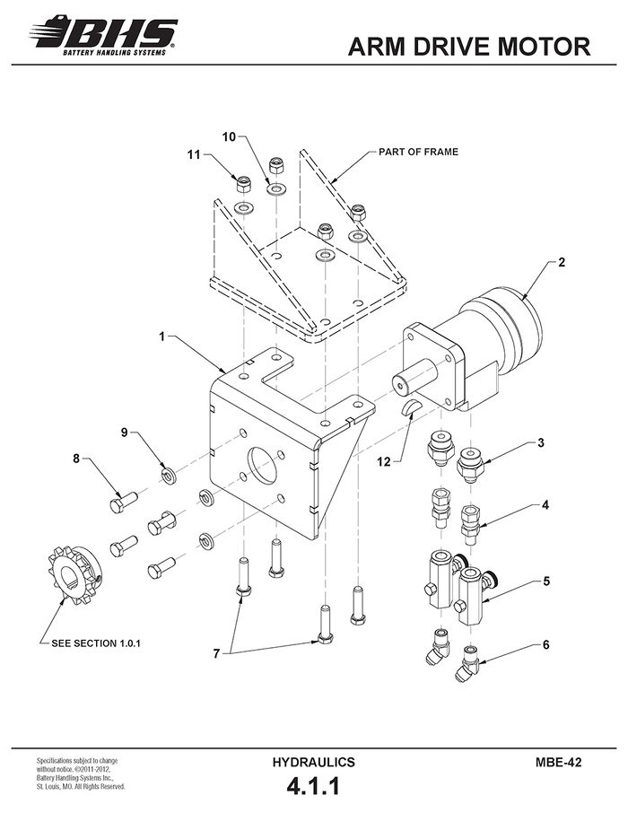
ARM DRIVE MOTOR
ITEM | BHS PART NUMBER | DESCRIPTION | REF. KIT NO. | NOTES | NO. REQ |
1 | 00145001 | MOUNT-MOTOR | 1 | ||
2 | HC0124 | MOTOR-HYDRAULIC-200CC | 1 | ||
3 | H1544 | ADAPTER-#6 JICM X #10 SAEM | 2 | ||
4 | H1587 | ADAPTER-#6 JICSW X #4 NPTM | 2 | ||
5 | HC0211 | VALVE-ADJUSTABLE FLOW CONTROL | 2 | ||
6 | H1565 | ELBOW-45 DEG-#6 JICM X #4 NPTM | 2 | ||
7 | HW0404 | BOLT-HHCS-3/8-16 X 1 1/2" | 4 | ||
8 | HW0402 | BOLT-HHCS-3/8-16 X 1" | 4 | ||
9 | HW0107 | WASHER-LOCK-3/8" | 4 | ||
10 | HW0108 | WASHER-FLAT-3/8"-SAE | 4 | ||
11 | HW0006 | NUT-NILN-3/8-16 | 4 | ||
12 | HW1071 | KEY-WOODRUFF-#808 STANDARD | SUPPLIED WITH MOTOR | 1 | |
13 | 08027002 | SHIM-THIN | .075" (NOT SHOWN) | A/R | |
14 | 08027003 | SHIM-THICK | .135" (NOT SHOWN) | A/R |
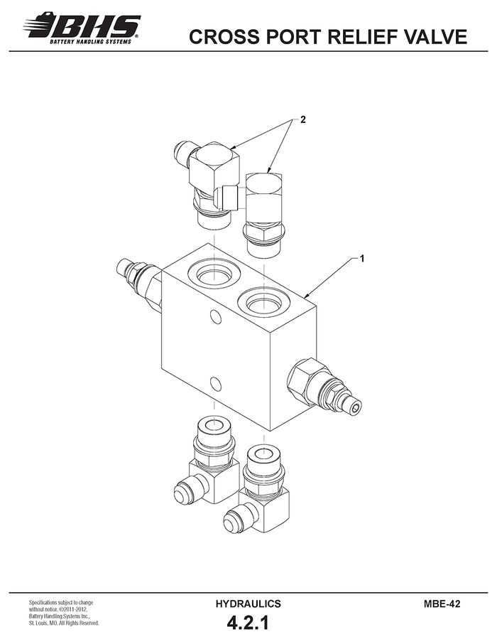
CROSS PORT RELIEF VALVE
ITEM | BHS PART NUMBER | DESCRIPTION | REF. KIT NO. | NOTES | NO. REQ |
1 | HC0262 | VALVE-CROSS PORT RELIEF | 1 | ||
2 | H1600 | ELBOW-90 DEG-#6 JICM X #10 SAEM | 4 | ||
3 | HW0308 | BOLT-HHCS-1/4-20 X 2 1/2" | MOUNTING HARDWARE (NOT SHOWN) | 2 | |
4 | HW0104 | WASHER-FLAT-1/4"-SAE | 4 | ||
5 | HW0002 | NUT-HEX-1/4-20 | 2 | ||
6 | HW0103 | WASHER-LOCK-1/4" | 2 |
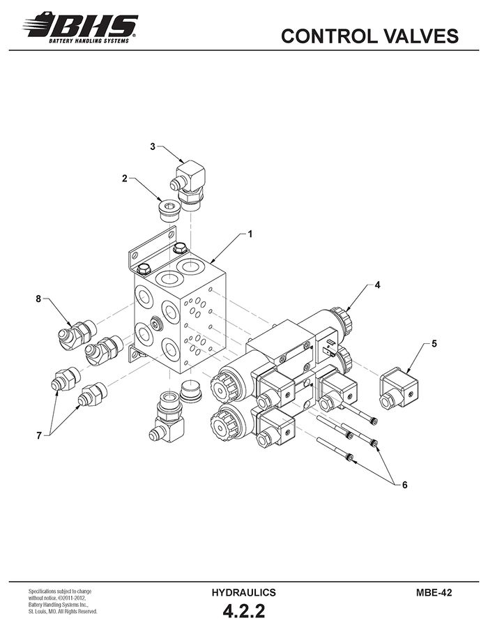
CONTROL VALVES
ITEM | BHS PART NUMBER | DESCRIPTION | REF. KIT NO. | NOTES | NO. REQ |
1 | HC0251 | MANIFOLD-2 BANK | 1 | ||
2 | H1641 | PLUG-#10 SAE | 2 | ||
3 | H1605 | ELBOW-90 DEG-#8 SAEM X #6 JICM | 2 | ||
4 | HC0222 | VALVE-SOLENOID-24VDC | 2 | ||
5 | HC0222-A | CONNECTOR-SOLENOID | 4 | ||
6 | HC0222-B | BOLT KIT-SOLENOID VAVLE | 4 BOLTS PER KIT | 2 | |
7 | H1546 | ADAPTER-#8 SAEM X #6 JICM | 2 | ||
8 | H1617 | ELBOW-45 DEG-#8 SAEM X #6 JICM | 2 | ||
9 | HW0303 | BOLT-HHCS-1/4-20 X 1" | MANIFOLD MOUNTING HARDWARE (NOT SHOWN) | 4 | |
10 | HW0104 | WASHER-FLAT-1/4 | 4 | ||
11 | HW0103 | WASHER-LOCK-1/4 | 4 | ||
12 | HW0002 | NUT-HEX-1/4-20 | 4 |
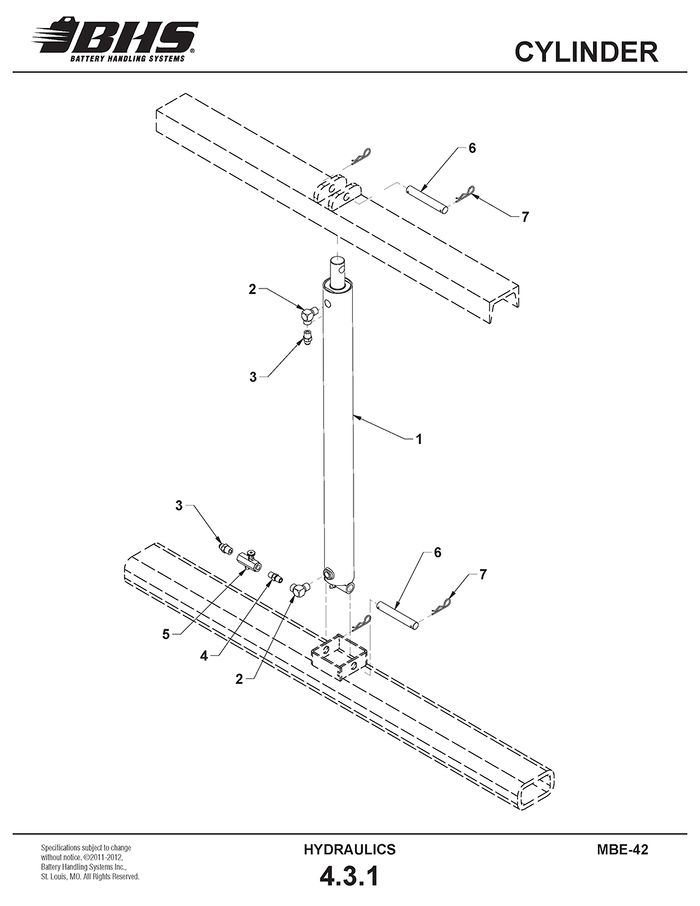
CYLINDER
ITEM | BHS PART NUMBER | DESCRIPTION | REF. KIT NO. | NOTES | NO. REQ |
1 | HC0404 | CYLINDER-LIFT | 1 | ||
2 | H0302 | ELBOW-STR-90 DEG-#6 NPT | 2 | ||
3 | H1504 | ADAPTER-#6 JICM X #4 NPTM | 2 | ||
4 | H0002 | NIPPLE-RED-#6 NPT X #4 NPT | 1 | ||
5 | HC0211 | VALVE-ADJUSTABLE FLOW CONTROL | 1 | ||
6 | 00197035 | PIN-CYLINDER | 2 | ||
7 | HW1058 | PIN-HITCH | 4 |
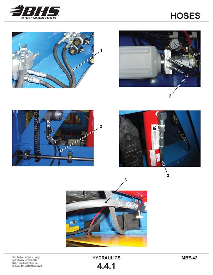
HOSES
ITEM | BHS PART NUMBER | DESCRIPTION | REF. KIT NO. | NOTES | NO. REQ |
1 | 00142001-92 | HOSE ASSEMBLY-1/4" X 15" | #6 JIC HOSE ENDS | 2 | |
2 | 00142001-24 | HOSE ASSEMBLY-1/4" X 36" | #6 JIC HOSE ENDS | 4 | |
3 | 00142001-45 | HOSE ASSEMBLY-1/4" X 108" | #6 JIC HOSE ENDS | 2 |
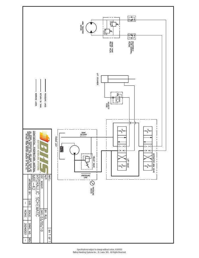
HYDRAULIC SCHEMATIC
ELECTRICAL
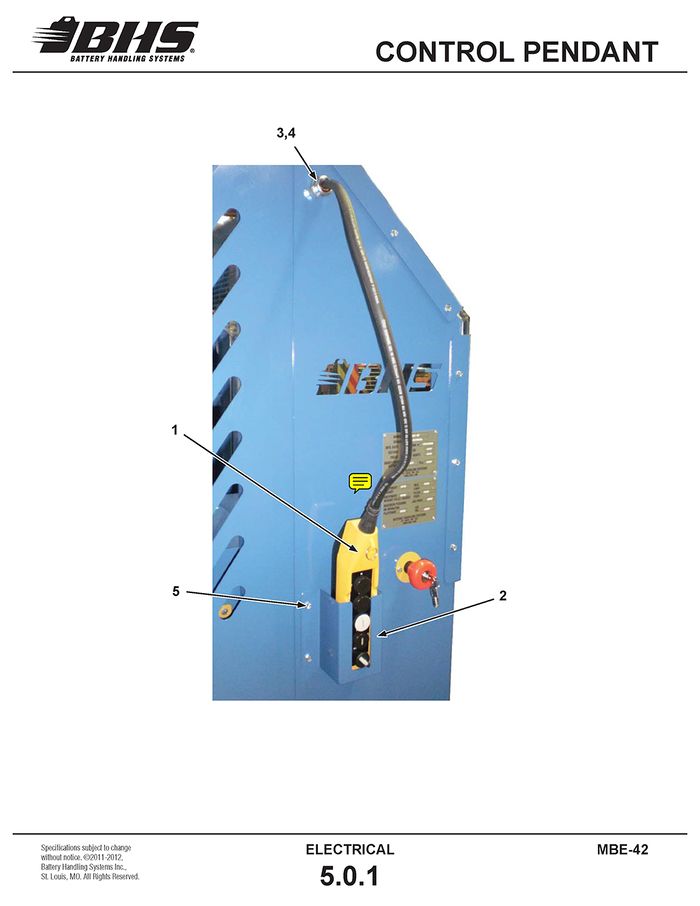
CONTROL PENDANT
ITEM | BHS PART NUMBER | DESCRIPTION | REF. KIT NO. | NOTES | NO. REQ |
1 | E0818 | PENDANT | 1 | ||
2 | 35017076-2 | MOUNT-PENDANT | 1 | ||
3 | E0618 | LOCKNUT-CONDUIT-3/4" | 1 | ||
4 | E0613 | RESTRAINT-3/4" | GRIP SIZE .500" TO .625" | 1 | |
5 | HW0301 | BOLT-SELF-TAP “F”-1/4-20 X 1/2" | 4 | ||
6 | E0819 | SWITCH-VACUUM | REPLACEMENT SWITCH | A/R |
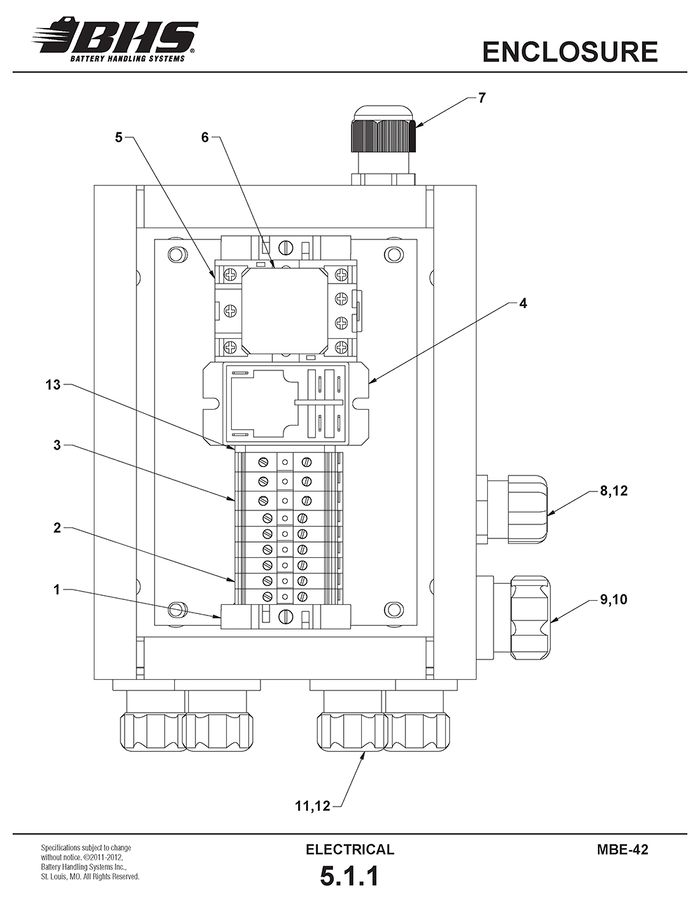
ENCLOSURE
ITEM | BHS PART NUMBER | DESCRIPTION | REF. KIT NO. | NOTES | NO. REQ |
1 | YE0406 | END STOP | 2 | ||
2 | YE0401 | TERMINAL BLOCK-SMALL | 6 | ||
3 | YE0402 | TERMINAL BLOCK-MEDIUM | 3 | ||
4 | YE0206 | RELAY-30A | 1 | ||
5 | YE0607 | BASE-RELAY | 1 | ||
6 | YE0307 | RELAY-POWER | 1 | ||
7 | 83F3335 | RESTRAINT-1/2" | 1 | ||
8 | E0622 | RESTRAINT-1/2" | GRIP SIZE .450" TO .560" | 1 | |
9 | E0613 | RESTRAINT-3/4" | GRIP SIZE .500" TO .625" | 1 | |
10 | E0618 | LOCKNUT-CONDUIT-3/4" | NOT SHOWN | 1 | |
11 | E0616 | RESTRAINT-1/2" | GRIP SIZE .250" TO .375" | 4 | |
12 | E0617 | LOCKNUT-CONDUIT-1/2” | NOT SHOWN | 5 | |
13 | YE0405 | END BARRIER | 1 |
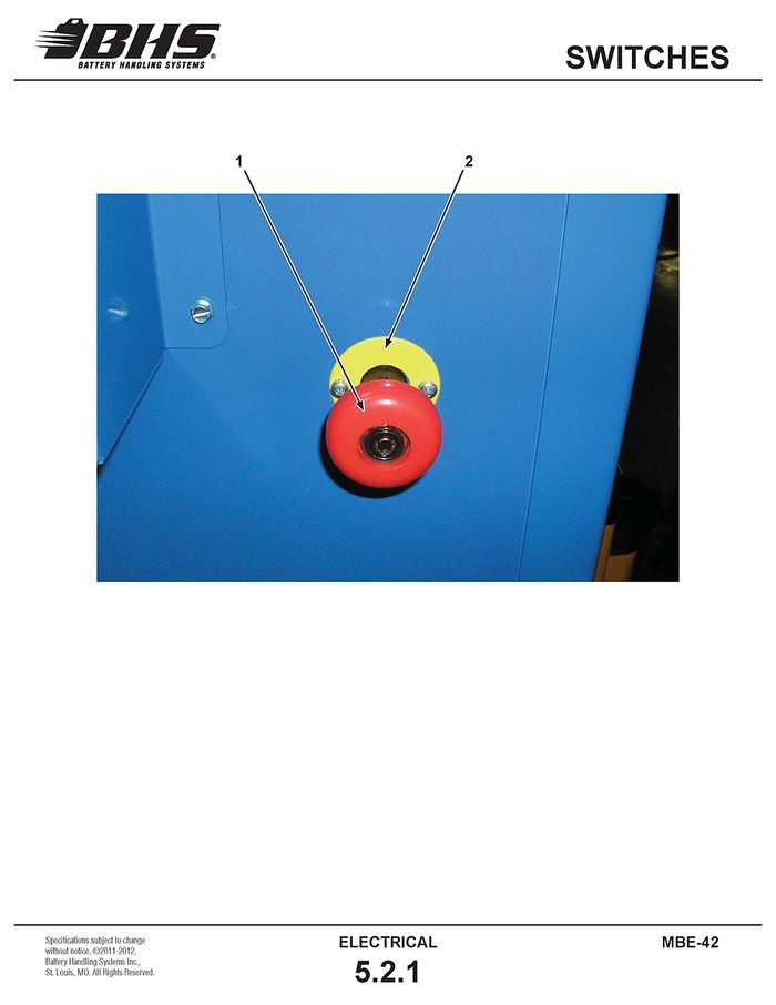
SWITCHES
ITEM | BHS PART NUMBER | DESCRIPTION | REF. KIT NO. | NOTES | NO. REQ |
1 | 800113380 | SWITCH-EMERGENCY STOP | INCL. MOUNTING HARDWARE | 1 | |
2 | 35037001 | LEGEND PLATE - EMERGENCY STOP | 1 | ||
3 | E0361 | KEY-EMERGENCY STOP | SET OF 2 (NOT SHOWN) | A/R |
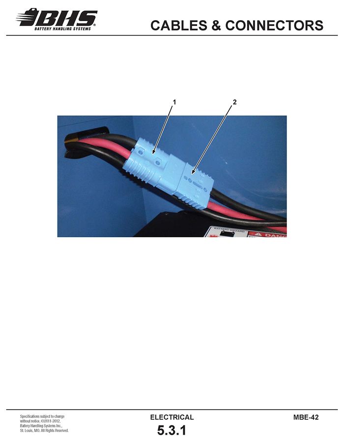
CABLES & CONNECTORS
ITEM | BHS PART NUMBER | DESCRIPTION | REF. KIT NO. | NOTES | NO. REQ |
1 | 35032002 | CABLE ASSEMBLY-BATTERY SIDE | 1 | ||
2 | 35032003 | CABLE ASSEMBLY-EXTRACTOR SIDE | 1 |
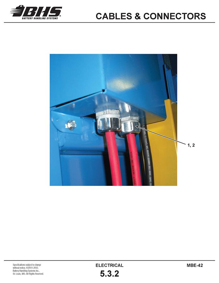
ITEM | BHS PART NUMBER | DESCRIPTION | REF. KIT NO. | NOTES | NO. REQ |
1 | E0634 | RESTRAINT-3/4" | GRIP SIZE .375" TO .500" | 2 | |
2 | E0618 | LOCKNUT-CONDUIT-3/4" | 2 |
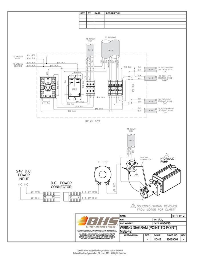
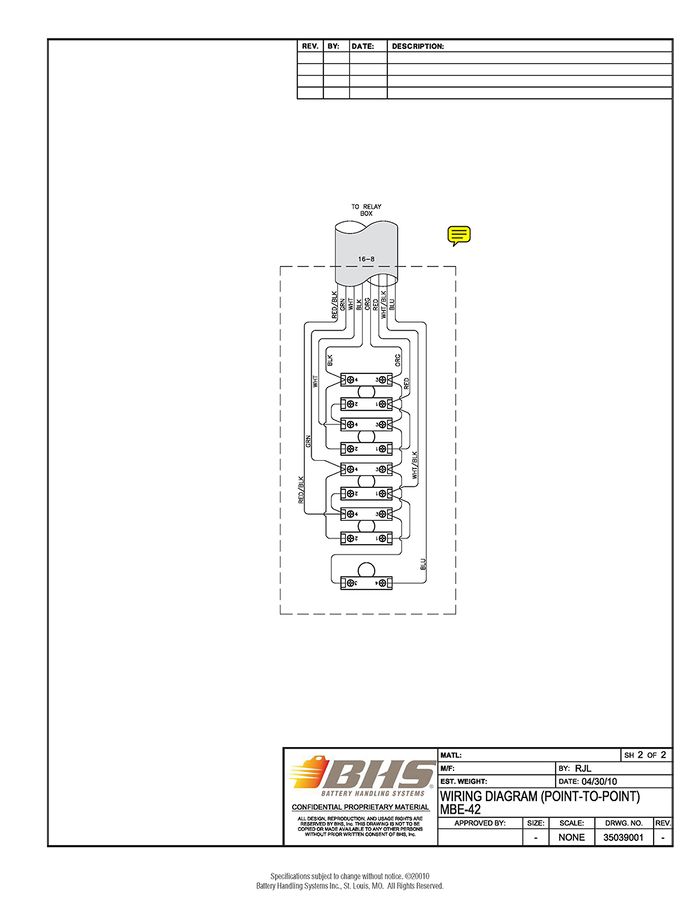
ELECTRICAL SCHEMATIC
PARTS KITS
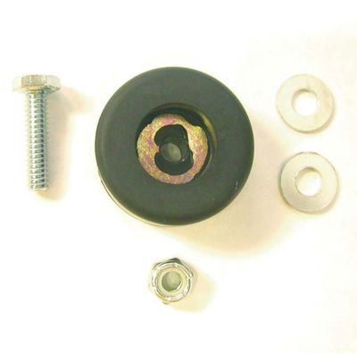
RUBBER BUMPER KIT
P/N: 80092001
QTY |
PART# |
DESCRIPTION |
1 | HW1037 | BUMPER-RUBBER-RECESSED |
2 | HW0104 | WASHER-FLAT-1/4”-SAE |
1 | HW0003 | NUT-NILN-1/4-20 |
1 | HW0303 | BOLT-HHCS-1/4-20 X 1” |
BATTERY EXTRACTOR
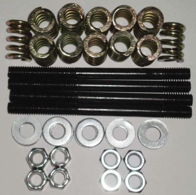
VACUUM STUD SPRING KIT
P/N: HW-KIT-2
|
QTY |
PART# |
DESCRIPTION |
|
4 |
HW0006 |
NUT-NILN-3/8-16 |
20 |
HW0108 |
WASHER-FLAT-3/8"-SAE |
4 |
HW0428 |
STUD-3/8-16 X 5" |
12 |
HW1001 |
SPRING-3/8" |
4 |
HW0424 |
NUT-JAM-3/8-16 |
10" VACUUM CUP ASSEMBLY
P/N: 00162001
|
QTY |
PART# |
DESCRIPTION |
|
1 |
N/A |
10" VACUUM CUP |
1 |
00117059 |
PLATE-ADAPTER-VACUUM CUP |
4 |
HW0328 |
BOLT-HHCS-5/16-18 X 3/4" |
1 |
P0505 |
BUSHING-RED-#6 NPT X #4 FNPT-BRASS |
1 |
P0506 |
ELBOW-STR-90 DEG-#4 NPT-BRASS |
1 |
P0401 |
ELBOW-#4 NPTM X 1/4" BARB-BRASS |
24 |
HW0108 |
WASHER-FLAT-3/8"-SAE |
BATTERY EXTRACTOR
12" VACUUM CUP ASSEMBLY
P/N: 00162003
|
QTY |
PART# |
DESCRIPTION |
|
1 |
00166001 |
CASTING-12" VACUUM CUP |
1 |
00165001 |
FRONT PLATE-12" VACUUM CUP |
1 |
00164001 |
RUBBER PAD-12" VACUUM CUP |
8 |
HW0311 |
BOLT-FHSCS-1/4-20 X 3/4" |
ATC VACUUM PUMP KIT (24V)
P/N: 80062002
QTY |
PART# |
DESCRIPTION |
1 | P0503 | NIPPLE-#4 NPT-BRASS |
1 | P0506 | ELBOW-STR-90 DEG-#4 NPT-BRASS |
1 | P0208 | FILTER |
1 | P0205 | SOLENOID-12V |
1 | P0002 | VACUUM PUMP-24V |
STATEMENT OF WARRANTY
Statement of Warranty
Click here for details on BHS' Statement of Warranty.
