IOP-146 PGC-PDC
Looking for a specific replacement part? Ctrl-F (or Command-F for Mac users) brings up your browsers search panel and can search any text on the entire web page. Find parts by searching a part # or part description.
Register your equipment with BHS Optima, BHS's free app.
California Residents: WARNING: This product contains chemicals known to the State of California to cause cancer and/or reproductive harm, and birth defects or other reproductive harm. Learn more here.
Power Drive Gantry Crane (PGC-PDC) Parts & Service Manual
TP-603 - SAFETY AND DE-ENERGIZATION PROCEDURES
GENERAL SAFETY
- Read and understand all instructions and warnings before using or servicing this equipment.
- Keep these instructions for future reference.
- For the purpose of this document, Portable Gantry Crane (PGC) will refer to the gantry structure as well as the hoist, functioning as one unit.
- Refer to the hoist manufacturer’s operating and maintenance instructions for proper operation and service procedures before operating or performing any service or maintenance to the PGC.
- PGC units shall only be used to handle industrial lead-acid batteries using a manufacturer approved battery lifting attachment.
- PGC units shall only be used indoors in an industrial setting on a hard, nonslip, and level floor without defects including but not limited to: holes, gouges, cracks, drains or obstacles.
- A licensed structural engineer should be consulted prior to installing a PGC on any building level other than the ground floor.
- PGC units are not designed to be shipped or transported after initial delivery.
- PGC units that do not travel on a designated guidance track should be maneuvered by two operators - one at each end of the PGC.
- Perform system and safety check before operating.
- Failure to follow these instructions and warnings may result in property damage, personal injury or death.
WORK AREA
- Keep work area clean and well lit. Cluttered work areas and poor lighting can lead to accidents.
- Clean up/contain any fluid spills immediately to prevent slips or falls.
- Be aware of potential hazards when performing any service or maintenance to the unit.
SERVICE & MAINTENANCE
Service personnel shall wear Personal Protective Equipment (PPE) appropriate for the task being performed.
LOCKOUT/TAGOUT
Lockout/tagout the PGC per your corporate policy, if PGC is damaged or not functioning properly. Lockout/tagout and de-energize all systems prior to performing any maintenance or service to PGC.
LEAD-ACID BATTERIES-EXPLOSION HAZARD
Do not allow open flames or sparks of any kind near a battery. Highly explosive gas is generated when charging a battery that can remain in battery cells for extended periods of time after charging is complete.
- Always wear appropriate PPE including rubber apron, gloves, boots and full face shield when performing service or maintenance to any lead-acid batteries.
- Do not place metal or other conductive objects on top of battery. Arcing may occur causing damage to the battery and/or serious personal injury or death.
- Use only chargers matching the voltage and amperage of the battery being charged. Overcharging a battery can cause damage to the battery, charger and/or serious personal injury or death.
- Turn off charger before disconnecting battery from charger. Arcing between battery and charger connectors can cause damage to the connectors and/or serious personal injury or death.
OPERATIONAL SAFETY
OPERATIONAL SAFETY
- Only personnel trained in the proper and safe operation of PGC units may operate or service the PGC.
- Operators shall wear appropriate PPE suitable for working with industrial lead-acid batteries while operating the PGC (see prior page).
- All data plates, warning labels, placards, etc. shall be in place and legible at all times. Contact BHS for replacement data plates, warning labels, placards or instructions.
- All users and service personnel shall be familiar with the meaning and risks associated with all data plates, warning labels, etc.
- All operators and service personnel shall be aware of potential crush and shear points while operating or servicing the PGC.
- PGC shall be operated in an area with ambient light levels of at least 50 lux.
- Keep at least a straight arms length distance from battery while transporting a battery.
- Avoid abrupt changes in direction when transporting a battery on the PGC to prevent loss of the battery and/ or loss of control of the PGC unit.
- Watch for personnel, batteries, charger cables or other obstructions in the PGC travel path.
- Remove the PGC from service if the PGC or hoist is damaged, defective, or operating improperly (or becomes such while operating) until repairs can be made to correct any problem(s).
DO’s AND DON’T’s
- DO NOT exceed the maximum capacity of lowest rated component of a PGC unit.
- DO NOT modify or fit the PGC with attachments without prior, written approval from BHS.
- DO NOT perform any maintenance or service to the PGC with a battery loaded on the PGC.
- DO NOT use the PGC to lift, support or transport people.
- DO NOT operate the PGC with any guard or cover removed unless required for maintenance or repair.
- DO NOT operate the PGC with the electrical enclosure door open. Keep door latches secure.
- DO NOT change any program parameter on the Variable Frequency Drive (VFD).
- Use only BHS, Inc. programmed replacement Electronic Programming Modules (EPM’s).
- DO NOT run the PGC into the end stops.
- DO NOT try to push or maneuver a battery while in motion.
- DO NOT use your body weight to guide battery in or out of position.
- DO NOT operate the PGC if disengaged from the guidance track.
- DO NOT propel the PGC, battery and/or lifting device into equipment or personnel.
- Ensure the lift truck mast clears the lowest point of the PGC prior to driving the truck into the designated battery changing area.
- DO NOT use the PGC in a manner for which it is not intended. Some examples of prohibited use are but not limited to:
- As a vehicle jack
- To lift loads greater than its rated load capacity
- Where unintentional movement may exist
- Having direct contact with foodstuffs
- Always travel with the battery as low as possible.
- DO NOT use PGC with a twisted, kinked, damaged or worn load chain.
- DO NOT lift batteries over people.
- DO NOT step under a suspended battery.
- DO NOT operate PGC unless all persons are (and remain) clear of the suspended battery and moving gantry structure travel path.
- DO NOT operate PGC unless battery is centered under the hoist.
- DO NOT attempt to lengthen the load chain or repair a damaged load chain.
- Protect the PGC’s load chain from weld splatter* or other damaging contaminants.
- DO NOT use the load chain as a sling or wrap the load chain around a battery.
- DO NOT lift a battery unless the load chain is properly seated in the hoist’s chain wheel(s) or sprocket(s).
- DO NOT operate PGC beyond the limits of the load chain travel.
- DO NOT leave a battery suspended by the PGC unattended unless specific precautions have been taken.
- DO NOT allow the load chain or hook to be used as an electrical or welding ground*.
- DO NOT allow the load chain to be touched by a live welding electrode*.
- DO NOT operate PGC unless the approved battery lifting attachment is properly sized, properly seated in the load hook saddle and the load hook latch is closed.
- Lift battery carefully. Make sure battery is balanced, lifting device is properly engaged, and load holding action is secure before continuing.
- Ensure hoist limit switches function properly.
- Warn personnel of an approaching PGC or battery.
- Maintain a firm footing or be otherwise secure when operating the PGC.
- Check the hoist brake function by tensioning the hoist prior to each lift operation.
- Ensure there are no obstacles in the travel path that could present a trip hazard prior to operating the PGC.
- Ensure the hook latch is closed and not supporting any part of the battery lifting attachment.
- Ensure the battery is free to move and will clear all obstructions.
- Avoid swinging the battery, lifting device and/or load hook.
- Inspect the PGC regularly. Replace damaged or worn parts and keep appropriate records of service and maintenance.
- Use only manufacturer’s recommended parts when repairing the PGC.
- DO NOT use the hoist load limiting or warning device to measure a battery weight.
- DO NOT use the limit switches as routine operating stops unless expressly authorized by the manufacturer. Limit switches are emergency devices only.
- DO NOT allow your attention to be diverted from operating the PGC.
*NEVER weld inside a battery room. See LEAD-ACID BATTERIES-EXPLOSION HAZARD.
LIFTING DEVICE SAFETY
DO’s AND DON’T’s
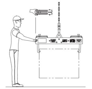
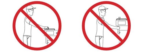
- Always maneuver the battery at a straight arm’s length with your hand at the end of the beam.
- DO NOT place hands or fingers on or near hooks when handling a battery.
- Inspect the lifting device for damage or wear prior to each use and keep appropriate records of service and maintenance.
- Ensure the battery lifting device is properly seated in the load hook saddle and the load hook latch is closed.
- Ensure the battery lifting device hooks are properly engaged prior to lifting a battery.
- Ensure the battery lifting device is (and remains) level at all times when handling a battery.
- DO NOT leave the battery lifting device attached to the load hook when not in use. (See OSHA regulation B30.20-203.)
CORRECT HAND PLACEMENT FOR MANEUVERING A MOTIONLESS BATTERY
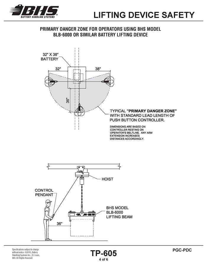
NOTE: When maneuvering a battery, the operator is within the “PRIMARY DANGER ZONE” and should use extreme caution.
INCORRECT HAND PLACEMENT FOR MANEUVERING A BATTERY
DE-ENERGIZATION
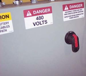
- To de-energize components external to the electrical enclosure, turn the disconnect switch on the enclosure to the “OFF” position. See Figure 1.
- To de-energize the entire PGC, including the electrical enclosure, disconnect power to the PGC or shut off the electrical branch circuit breaker.
- Wait 3 minutes before performing any service to the unit to allow the capacitors in the motor drive circuit to fully discharge.
FIGURE 1
GENERAL INFORMATION
SPECIFICATIONS
PGC-PDC Specifications - Imperial / Metric
PGC-10PDC | PGC-12PDC | PGC-14PDC | PGC-16PDC | PGC-18PDC | PGC-20PDC | |
Capacity | 4,000 lbs / 1814 kg | 4,000 lbs / 1814 kg | 4,000 lbs / 1814 kg | 4,000 lbs / 1814 kg | 4,000 lbs / 1814 kg | 4,000 lbs / 1814 kg |
Clear Between “A” Frame | 10’ / 3050 mm | 12’ / 3660 mm | 14’ / 4270 mm | 16’ / 4880 mm | 18’/ 5490 mm | 20’ / 6100 mm |
Overall Beam Length | 12’ / 3660 mm | 14’ / 4270 mm | 16’ / 4880 mm | 18’ / 5490 mm | 20’ / 6100 mm | 22’ / 6710 mm |
Overall Length Dimension | 12’ 9” / 3890 mm | 14’ 9” / 4500 mm | 16’ 9” / 5110 mm | 18’ 9” / 5720 mm | 20’ 9” / 6320 mm | 22’ 9” / 6930 mm |
Overall System Length 1 | 14’ / 4270 mm | 16’ / 4880 mm | 18’ / 5490 mm | 20’ / 6100 mm | 22’ / 6710 mm | 24’ / 7320 mm |
Nominal Track / Wheel Distance 2 | 11 ’5” / 3480 mm | 13’ 5” / 4090 mm | 15’ 5” / 4700 mm | 17’ 5” / 5310 mm | 19’ 5” / 5920 mm | 21 ’5” / 6530 mm |
Overall Height 3 | 11’ 1” / 3380 mm | 11’ 1” / 3380 mm | 11’ 3” / 3430 mm | 11’ 3” / 3430 mm | 11’ 5” / 3480 mm | 11’ 5” / 3480 mm |
I-Beam Size | 8” x 23# / 203.2 mm x 10.43 kg | 8” x 23# / 203.2 mm x 10.43 kg | 10” x 25.4# / 254.0 mm x 11.52 kg | 10” x 25.4# / 254.0 mm x 11.52 kg | 12” x 31.8# / 304.8 mm x 14.42 kg | 12” x 31.8# / 304.8 mm x 14.42 kg |
Weight | 1,260 lbs / 571.53 kg | 1,285 lbs / 582.87 kg | 1,320 lbs / 598.74 kg | 1,345 lbs / 610.08 kg | 1,425 lbs / 646.37 kg | 1,490 lbs / 678.85 kg |
Under Beam Clearance Height | 10’ 5” / 3170 mm | 10’ 5” / 3170 mm | 10’ 5” / 3170 mm | 10’ 5” / 3170 mm | 10’ 5” / 3170 mm | 10’ 5” / 3170 mm |
Under Chain Container Clearance Height | 8’ 5” / 2570 mm | 8’ 5” / 2570 mm | 8’ 5” / 2570 mm | 8’ 5” / 2570 mm | 8’ 5” / 2570 mm | 8’ 5” / 2570 mm |
Max A.C. Amp Draw with Hoist at 480V / 3Ph / 60Hz4 | 5.2 Amp | 5.2 Amp | 5.2 Amp | 5.2 Amp | 5.2 Amp | 5.2 Amp |
Travel Speed | 45 FPM / .2286 MPS | 45 FPM / .2286 MPS | 45 FPM / .2286 MPS | 45 FPM / .2286 MPS | 45 FPM / .2286 MPS | 45 FPM / .2286 MPS |
A-Frame Base Width | 68” / 1727.20 mm | 68” / 1727.20 mm | 68” / 1727.20 mm | 68” / 1727.20 mm | 68” / 1727.20 mm | 68” / 1727.20 mm |
3PGC-PDC Specifications - Imperial / Metric
3PGC-10PDC | 3PGC-12PDC | 3PGC-14PDC | 3PGC-16PDC | 3PGC-18PDC | 3PGC-20PDC | |
Capacity | 6,000 lbs / 2721.55 kg | 6,000 lbs / 2721.55 kg | 6,000 lbs / 2721.55 kg | 6,000 lbs / 2721.55 kg | 6,000 lbs / 2721.55 kg | 6,000 lbs / 2721.55 kg |
Clear Between “A” Frame | 10’ / 3050 mm | 12’ / 3660 mm | 14’ / 4270 mm | 16’ / 4880 mm | 18’ / 5490 mm | 20’ / 6100 mm |
Overall Beam Length | 12’ / 3660 mm | 14’ / 4270 mm | 16’ / 4880 mm | 18’ / 5490 mm | 20’ / 6100 mm | 22’ / 6710 mm |
Overall Length Dimension | 12’ 9” / 3890 mm | 14’ 9” / 4500 mm | 16’ 9” / 5110 mm | 18’ 9” / 5720 mm | 20’ 9” / 6320 mm | 22’ 9” / 6930 mm |
Overall System Length 1 | 14’ / 4270 mm | 16’ / 4880 mm | 18’ / 5490 mm | 20’ / 6100 mm | 22’ / 6710 mm | 24’ / 7320 mm |
Nominal Track / Wheel Distance 2 | 11’ 5” / 3480 mm | 13’ 5” / 4090 mm | 15’ 5” / 4700 mm | 17’ 5” / 5310 mm | 19’ 5” / 5920 mm | 21’ 5” / 6530 mm |
Overall Height 3 | 11’ 1” / 3380 mm | 11’ 1” / 3380 mm | 11’ 3” / 3430 mm | 11’ 3” / 3430 mm | 11’ 5” / 3480 mm | 11’ 5” / 3480 mm |
I-Beam Size | 8” x 23# / 203.2 mm x 10.43 kg | 10” x 25.4# / 254.0 mm x 11.52 kg | 10” x 25.4# / 254.0 mm x 11.52 kg | 12” x 31.8# / 304.8 mm x 14.42 kg | 15” x 42.9# / 381.0 mm x 19.46 kg | 15” x 42.9# / 381.0 mm x 19.46 kg |
Weight | 1,260 lbs / 571.53 kg | 1,320 lbs / 598.74 kg | 1,370 lbs / 621.42 kg | 1,455 lbs / 659.98 kg | 1,511 lbs / 685.38 kg | 1,627 lbs / 737.99 kg |
Under Beam Clearance Height | 10’ 5” / 3170 mm | 10’ 5” / 3170 mm | 10’ 5” / 3170 mm | 10’ 5” / 3170 mm | 10’ 5” / 3170 mm | 10’ 5” / 3170 mm |
Under Chain Container Clearance Height | 8’ 5” / 2570 mm | 8’ 5” / 2570 mm | 8’ 5” / 2570 mm | 8’ 5” / 2570 mm | 8’ 5” / 2570 mm | 8’ 5” / 2570 mm |
Max A.C. Amp Draw with Hoist at 480V / 3Ph / 60Hz4 | 6.8 Amp | 6.8 Amp | 6.8 Amp | 6.8 Amp | 6.8 Amp | 6.8 Amp |
Travel Speed | 45 FPM / .2286 MPS | 45 FPM / .2286 MPS | 45 FPM / .2286 MPS | 45 FPM / .2286 MPS | 45 FPM / .2286 MPS | 45 FPM / .2286 MPS |
A-Frame Base Width | 68” / 1727.20 mm | 68” / 1727.20 mm | 68” / 1727.20 mm | 68” / 1727.20 mm | 68” / 1727.20 mm | 68” / 1727.20 mm |
INSTALLATION
The Powered Gantry System you have purchased was tested and left the factory in top condition. Inspect unit for any freight damages before starting installation.
Your unit has been pre-assembled and pre-wired for your convenience. The following steps should be followed to ensure proper and safe operation. Area of installation should be cleared and uncluttered so a forklift and personnel can safely work in the area.
1) Lay "I" beam on floor in direction it is to be used. Remove "A" frame legs from shipping tees and locate which side of system control box will be mounted to and put that leg on the appropriate side. Gussets of "A" frames should point inward toward each other.
2) Install the 1/2" bolts through beam mounting pad and into legs. Lightly snug bolts - do not tighten at this point.
3) After bolts are in place, make sure legs are perpendicular to floor and parallel to each other. To accomplish this, measure the distance from center-to-center of wheels on top and bottom of "A" frames. Then cross square by measuring diagonally from wheel center to wheel center. Cross square dimensions should be within 1/4" of each other.
4) After unit is in a squared position, tighten up the beam mounting bolts and recheck squareness. Beam bolts should be torqued to approximately 75 - 90 lb/ft
5) While unit is still lying down, use beam clamps supplied to route cable for #2 drive motor assembly across top flange of beam. Cable ties or electrical tape should be used to attach cable up side of "A" frames so as not to have any hang points.
6) Unit can now be stood upright by positioning forklift under center of "I" beam and slowly raising. The assistance of one or two men on each leg is advisable to keep the unit stabilized and counteract any over swinging which could damage wheel assemblies.
7) Mark location of one side of track by using a chalk line to keep marks straight. Layout one section at a time and visually inspect to make certain each piece is straight. Minor bows can be adjusted by anchoring each end then forcing in bowed area and anchoring. (6 - 3/8" concrete anchors are supplied for each 10' section of track.
8) There are two ways the second track (if required) can be installed.
OPTION #1:
Measure center-to-center on wheels of gantry, then position second track 1/8" - 1/4" wider than this dimension to allow for beam and leg deflection while under load.
OPTION #2:
Wait until hoist and trolley are mounted and "A" frame wiring is connected, then pick up approximately 1/2 of maximum load being handled and then anchor the outboard track as system is powered down the track at 5' intervals.
NOTE: Refer to hoist manual for proper set-up and adjustment procedures.
OPERATION
Read and understand all instructions and warnings, including TP-605 - Safety and De-energization Procedures, prior to operating this equipment.
The following instructions will guide you through the basic steps necessary to operate and change batteries with a PGC-PDC equipped with a BHS model BLB-6000 lifting beam.
NOTE: Deviation from the following procedure may be required due to variation of particular battery room design and/or layout.
- If not already in place, position industrial truck (pallet or lift truck) which requires a battery change in the appropriate staging area.
- Disconnect the battery leads and remove any battery restraints. Refer to the lift truck manual for proper procedure.
- Position the hoist to the side (horizontally on the beam) on which the battery is to be extracted from the lift truck.
- Move the PGC into position over the lift truck, aligning the hoist lift chain with the slot in the overhead guard of the lift truck.
- Position the lifting beam in the direction the battery will be removed (typically parallel with the battery) and adjust the height to allow the lifting beam to be positioned over the battery.
- Lower the lifting beam and engage the lifting beam hooks into the battery lifting eyes.
- Ensure both hooks are fully engaged in the battery lifting eyes and carefully lift the battery a sufficient distance to clear any structure of the lift truck battery compartment. Observe the clearance of the hoist block and overhead guard.
- Move the battery out of the battery compartment until completely clear of the lift truck.
- Move the PGC to an open position on the battery stands and align the battery with the open slot ensuring sufficient clearance on both sides of the battery.
- Adjust the height of the battery sufficient to clear the 11. battery stand deck.
- Move the battery completely into the open position while observing the clearance of the lifting beam and hook block with battery stand charger shelf.
- Lower the battery onto the battery stand deck until the lifting beam hooks disengage from the battery lifting eyes. NOTE: It may be necessary to manually disconnect the lifting hooks if the lifting beam is equipped with locking-style hooks.
- Maneuver the lifting beam as required by lifting and turning the beam so the hooks are clear of any batteries and battery/charger cables. Ensure the lifting beam and/or hook block is clear of the charger shelf and any battery/charger cables.
- Move the lifting beam away from the battery.
- Move the PGC into position with the charged battery to be installed into the lift truck and disconnect the battery from the charger.
- The above process can be used to remove a charged battery from the battery stand and install it into the lift truck.
- If accessible, use a lift truck of sufficient capacity along with a pallet to carefully lift the battery such that the lifting device can be disconnected from the battery. If the battery is too low to allow a pallet to be placed under it, lift the battery directly by the lift truck forks.
- Lower the battery for safe travel and slowly transport the battery out of the immediate area so repairs can be made
- Check all bolts on wheels, drive motor mounts and I-Beam for tightness. #Check drive wheels chains for proper tension and lubricate with light machine oil or spray chain lubricant.
- Hoist lift chain should be wiped with a towel saturated with light machine oil.
- The two drive wheels and two idler casters are equipped with grease fittings. A sufficient amount of grease should be pumped into grease fittings until grease just starts coming out of axle washers inside of forks.
- Inspect lift chain for excessive wear, damaged or twisted links. #Inspect gear boxes for leakage.
Refer to the lifting attachment manual for proper hook engagement and operating procedures.
DO NOT allow the hook block to come in contact with the overhead guard. Damage to the hook block and or overhead guard may occur.
DO NOT place hands or fingers on or near hooks when handling a battery. A sudden unexpected shift of the battery or lifting beam could crush or sever hands and fingers. Refer to Safety and De-energization Procedures TP-605 for proper handling of a BHS lifting beam and battery.
DO NOT allow the hook block to come in contact with the overhead guard. Damage to the hook block and or overhead guard may occur.
DO NOT allow the lifting beam or hook block to come in contact with or become entangled with the charger shelf or battery/charger cables. Damage to the lifting beam, charger shelf, and battery/chargers may occur.
ALWAYS be sure charging has been completed and charger is not still charging battery. Dangerous sparking/arcing can occur if battery is unplugged from charger while charging.
DO NOT drive the PGC into the travel path end stops. The end stops are designed to prevent the PGC from accidentally traveling beyond its designated travel path. Driving the PGC into the end stops could cause damage to the end stop and/or the PGC.
Driving the PGC into the end stops with a battery suspended form the hoist will cause the battery to swing which could cause the battery to fall. Serious personal injury or death may occur.
MANUAL UNLOADING
Lockout/tagout and de-energize all equipment prior to manually unloading any battery.
In the event of power loss or an operational malfunction of the PGC and/or hoist not allowing a battery to be unloaded using normal operating procedures, it is recommended to unload the battery from the hoist using a lift truck.
Should the status of the PGC/hoist not permit access to or not allow for safe, manual unloading, only repairs required to safely maneuver the PGC/hoist to a position allowing for safe unloading should be made. Once the battery is safely unloaded, any remaining repairs can be made.
Extreme care should be taken when working around a suspended load as well as equipment suspending a load. Unexpected movement of the equipment could cause the load and/or equipment to shift, possibly causing the load to fall. Serious personal injury or death may occur.
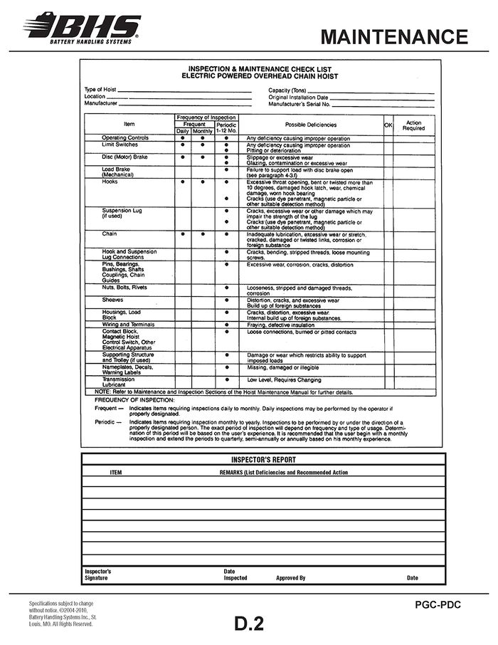
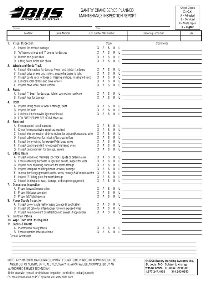
MAINTENANCE
Every effort has been made in design and manufacturing of this unit to make it as trouble free and low maintenance as possible. The gear boxes are lifetime lubricated and require no service. The following are a few steps to be taken on a regular basis dependent upon environment and application. A good starting point is every 60 days then adjust your schedule as conditions require.
GANTRY CRANE SERIES PLANNED MAINTENANCE INSPECTION REPORT
SPARE PARTS
The following items are recommended by the factory to have on hand for PGC-PDC models to minimize any downtime due to minor breakdown that may occur under normal operating conditions.
BHS PART NUMBER | DESCRIPTION | QTY | REFERENCE SECTION | NOTES |
HW0306 | BOLT-FHSCS-1/4-20 X 1" | 8 | 2.0.1 | |
14024010 | SPROCKET-36T | 1 | 2.0.1 | |
14026007 | WHEEL-POLY- MODIFIED | 1 | 2.0.1 | VERIFY TYPE PRIOR TO ORDERING |
14026006 | WHEEL-V-GROOVE-MODIFED | 1 | ||
E1219 | FUSE | 1 | 3.0.1 | 0.8A (ALL UNITS) |
E0340 | FUSE | 3 | 10A (208/240/480V UNITS) | |
E0339 | FUSE | 3 | 12A (ALL UNITS) | |
X350004 | FUSE | 3 | 12A (575V UNITS) |
Use only BHS approved replacement parts.
BHS recommends that a full maintenance inspection report similar to the one provided be done at least once a month.
Any parts found to be excessively worn or damaged should promptly be replaced unless said parts pose a safety risk to the operator and/or extractor, in which case the unit should be removed from service until the problem(s) are remedied (See Operator’s Daily Checklist.)
GANTRY CRANE SERIES PLANNED MAINTENANCE INSPECTION REPORT
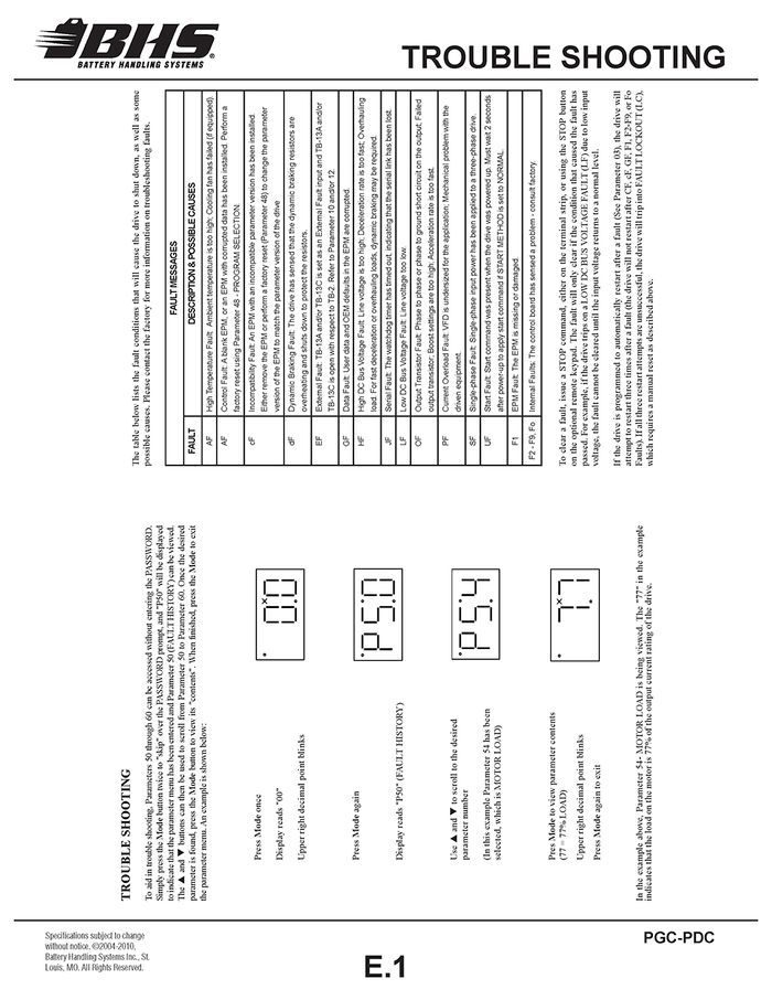
TROUBLE SHOOTING
PARTS SECTIONS
CHASSIS
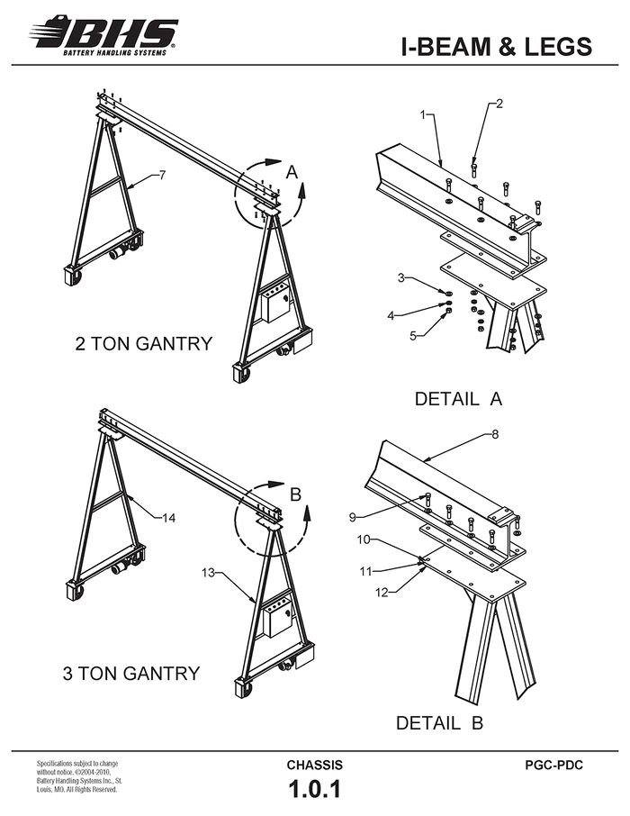
I-BEAM & LEGS
ITEM | BHS PART NUMBER | DESCRIPTION | NOTES | NO. REQ |
1 | PGC-BEAM-10 | I-BEAM-12’ X 8”-23#-6 HOLE | 2-TON | 1 |
PGC-BEAM-12 | I-BEAM-14’ X 8”-23#-6 HOLE | 2-TON | 1 | |
PGC-BEAM-14 | I-BEAM-16’ X 10”-25.4#-6 HOLE | 2-TON | 1 | |
PGC-BEAM-16 | I-BEAM-18’ X 10”-25.4#-6 HOLE | 2-TON | 1 | |
PGC-BEAM-18 | I-BEAM-20’ X 12”-31.8#-6 HOLE | 2-TON | 1 | |
PGC-BEAM-20 | I-BEAM-22’ X 12"-31.8#-8 HOLE | 2-TON | 1 | |
2 | HW0504 | BOLT-HHCS-1/2-13 X 2 | 12 | |
3 | HW0111 | WASHER-FLAT-1/2-SAE | 24 | |
4 | HW0110 | WASHER-LOCK-1/2 | 12 | |
5 | HW0007 | NUT-HEX-1/2-13 | 12 | |
6 | 14015001 | 2-TON LEG FRAME | PANEL SIDE | 1 |
7 | 14015002 | 2-TON LEG FRAME | NON-PANEL SIDE | 1 |
8 | 3PGC-BEAM-12 | I-BEAM-14’ X 10”-25.4#-8 HOLE | 3-TON | 1 |
3PGC-BEAM-14 | I-BEAM-16’ X 10”-25.4#-8 HOLE | 3-TON | 1 | |
3PGC-BEAM-16 | I-BEAM-18’ X 12”-31.8#-8 HOLE | 3-TON | 1 | |
3PGC-BEAM-18 | I-BEAM-20' X 15”-42.9#-8 HOLE | 3-TON | 1 | |
9 | HW0504 | BOLT-HHCS-1/2-13 X 2 | 16 | |
10 | HW0111 | WASHER-FLAT-1/2-SAE | 32 | |
11 | HW0110 | WASHER-LOCK-1/2 | 16 | |
12 | HW0007 | NUT-HEX-1/2-13 | 16 | |
13 | 15015001 | 3-TON LEG FRAME | PANEL SIDE | 1 |
14 | 15015002 | 3-TON LEG FRAME | NON-PANEL SIDE | 1 |
DRIVE & IDLER WHEELS
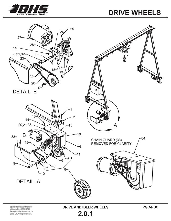
DRIVE WHEELS
ITEM | BHS PART NUMBER | DESCRIPTION | NOTES | NO. REQ |
1 | HW0511 | BOLT-HHCS-1/2-13 X 3 3/4 | 8 | |
2 | HW0111 | WASHER-FLAT-1/2-SAE | 16 | |
3 | 14025001 | PGC DRIVE WHEEL MOUNT | PANEL SIDE | 1 |
14025003 | PGC DRIVE WHEEL MOUNT | NON-PANEL SIDE | 1 | |
4 | HW0306 | BOLT-FHSCS-1/4-20 X 1 | 16 | |
5 | 14024010 | SPROCKET-GANTRY POWER DRIVE | 36 TOOTH (SEE NOTES) | 2 |
6 | 14027008 | SPACER-SPROCKET/WHEEL | 2 | |
7 | 14026006 | WHEEL-MODIFIED-V-GROOVE | 2 | |
14026007 | WHEEL-MODIFIED-POLY | 2 | ||
8 | 14022014 | V-GROOVE WHEEL ASSEMBLY | W/ 36 TOOTH SPROCKET (SEE NOTES) | 1 |
14022013 | POLY WHEEL ASSEMBLY | W/ 36 TOOTH SPROCKET (SEE NOTES) | 1 | |
9 | HW0701 | BOLT-HHCS-3/4-10 X 5 1/2 | 2 | |
10 | HW0119 | WASHER-FLAT-1-SAE | 2 | |
11 | HW0017 | NUT-HEX-3/4-10 | 2 | |
12 | C0090-1 | SPANNER-BEARING-DRIVE WHEEL | 2 | |
13 | HW0402 | BOLT-HHCS-3/8-16 X 1 1/4 | 12 | |
14 | HW0108 | WASHER-FLAT-3/8-SAE | 4 | |
15 | HW0110 | WASHER-LOCK-1/2 | 8 | |
16 | HW0007 | NUT-HEX-1/2-13 | 8 | |
17 | HW0107 | WASHER-LOCK-3/8 | 8 | |
18 | HW0108 | WASHER-FLAT-3/8-SAE | 8 | |
19 | HW0328 | BOLT-HHCS-5/16-18 X 3/4 | 8 | |
20 | HW0106 | WASHER-FLAT-5/16-SAE | 16 | |
21 | HW0004 | NUT-HEX-5/16-18 | 8 | |
22 | PT0003-1 | SPROCKET-41 PITCH-13T-3/4 | 2 | |
23 | PT0005 | LINK-CONNECTING-#41 | 2 | |
24 | 14027009-2 | MOUNT-GEARBOX | 4 | |
25 | PT0100 | GEAR BOX-30:1 | 2 | |
26 | 00158001-21 | CHAIN-DRIVE-#41 | FOR USE W/ 40 TOOTH SPROCKET (SEE NOTES) | 2 |
00158001-26 | CHAIN-DRIVE-#41 | FOR USE W/ 36 TOOTH SPROCKET (SEE NOTES) | 2 | |
27 | E0121-1 | MOTOR-1/2 HP | 56C-1750RPM INV RATED TS | 2 |
28 | HW0103 | WASHER-LOCK-1/4 | 8 | |
29 | HW0329 | BOLT-HHCS-6MM X 12MM | 8 | |
30 | - | SHAFT | INCLUDED WITH PT0100 | 2 |
31 | - | WASHER | INCLUDED WITH PT0100 | 2 |
32 | - | RETAINING RING | INCLUDED WITH PT0100 | 2 |
33 | 14017015-2 | GUARD-CHAIN | 2 | |
34 | 14022003 | DRIVE WHEEL ASSEMBLY - V GROOVE | NON-PANEL SIDE | 1 |
14022005 | DRIVE WHEEL ASSEMBLY - V GROOVE | PANEL SIDE | 1 | |
14022004 | DRIVE WHEEL ASSEMBLY - POLY OPTION | NON-PANEL SIDE | 1 | |
14022006 | DRIVE WHEEL ASSEMBLY - POLY OPTION | PANEL SIDE | 1 | |
35 | HW0105 | WASHER-LOCK-5/16 | 8 | |
36 | 00197017 | KEY-3/16 X 1 | FOR ITEM 22 (NOT SHOWN) | 1 |
NOTE: 40 TOOTH SPROCKETS NO LONGER AVAILABLE. MUST CONVERT SPROCKETS AND CHAIN TO 36 TOOTH.
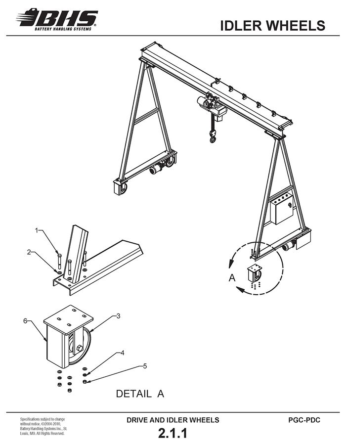
IDLER WHEELS
ITEM | BHS PART NUMBER | DESCRIPTION | NOTES | NO. REQ |
1 | HW0511 | BOLT-HHCS-1/2-13 X 3 3/4 | 8 | |
2 | HW0111 | WASHER-FLAT-1/2-SAE | 16 | |
3 | C0040 | CASTER-10 X 3 | FOR USE W/ V-GROOVE OPTION | 2 |
C0095 | CASTER-10 X 3-POLY | FOR USE W/ POLY WHEEL OPTION | 2 | |
4 | HW0110 | WASHER-LOCK-1/2 | 16 | |
5 | HW0007 | NUT-HEX-1/2-13 | 16 | |
6 | 14025002 | MOUNT-CASTER | 2 |
ELECTRICAL
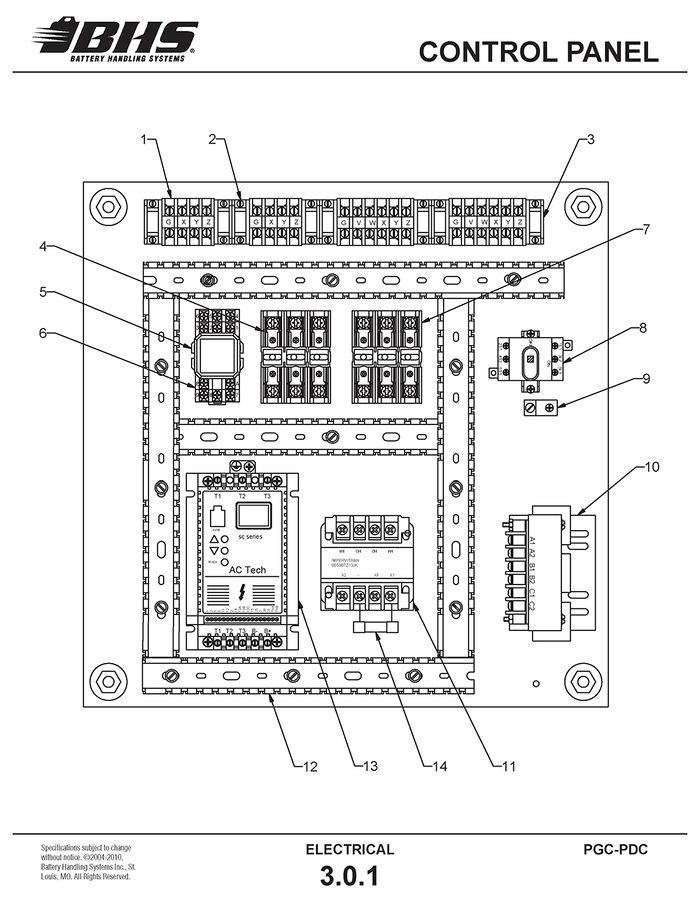
CONTROL PANEL
ITEM | BHS PART NUMBER | DESCRIPTION | NOTES | NO. REQ |
1 | E1020 | BLOCK-TERMINAL-LARGE-EA1 | 20 | |
2 | E1040 | BARRIER-TERMINAL-END-LARGE | 4 | |
3 | E0908 | TRACK-MOUNTING | 1 | |
4 | E0340 | FUSE-ATMR10 | 10A | 3 |
X350004 | FUSE | 12A-FAST ACTING | 3 | |
5 | E1012 | RELAY | 11 PIN | 1 |
6 | E1013 | SOCKET-RELAY-11 PIN | 1 | |
7 | E0339 | FUSE-FLQ-12 | 12A, 600V | 3 |
8 | E0122-1 | BASE-DISCONNECT | † SEE NOTES | 1 |
9 | E0341 | CLIP-GROUNDING | 1 | |
10 | RM0004N30 | LINE REACTOR | FOR USE WITH 208/240V | 1 |
RM0002M12 | LINE REACTOR | FOR USE WITH 480V | 1 | |
X350003 | LINE REACTOR - 575 VOLT | FOR USE WITH 575V | 1 | |
11 | E1212 | TRANSFORMER | 240/480V TO 120V | 1 |
E0208 | TRANSFORMER | 208V TO 120V | 1 | |
X350000 | TRANSFORMER | 575V TO 120V | 1 | |
12 | E1023 | WIREWAY | AR | |
13 | E0015 | VARIABLE FREQUENCY DRIVE (VFD) | FOR USE WITH 208/240V | 1 |
E0014 | VARIABLE FREQUENCY DRIVE (VFD) | FOR USE WITH 480V | 1 | |
X350002 | VARIABLE FREQUENCY DRIVE (VFD) | FOR USE WITH 575V | 1 | |
14 | E1219 | FUSE | 0.8A, 240/480V | 1 |
15 | E0123-1 | HANDLE-DISCONNECT | † SEE NOTES (NOT SHOWN) | 1 |
16 | E0124-2 | SHAFT-DISCONNECT | †† SEE NOTES (NOT SHOWN) | 1 |
17 | E0128 | ADAPTER-SHAFT | † SEE NOTES (NOT SHOWN) | 1 |
† FOR UNITS BUILT PRIOR TO 01/12/10, A SHAFT ADAPTER (ITEM# 17) IS REQUIRED WHEN REPLACING EITHER ITEM #8 OR ITEM #15.
† † FOR UNITS BUILT PRIOR TO 01/12/10, ITEM #’S 8 AND 15 MUST BE REPLACED IF REPLACING ITEM #16.
IF THERE IS ANY QUESTION AS TO THE THE ITEMS NEEDED WHEN ORDERING A NEW DISCONNECT BASE, SHAFT OR HANDLE, PLEASE CONTACT BHS TECH SUPPORT WITH THE MANUFACTURER’S PART NUMBER OF THE DISCONNECT BASE AND HANDLE.
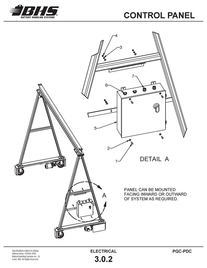
ITEM | BHS PART NUMBER | DESCRIPTION | NOTES | NO. REQ |
1 | HW0402 | BOLT-HHCS 3/8-16 X 1 | 4 | |
2 | HW0108 | WASHER-FLAT 3/8 SAE | 8 | |
3 | HW0107 | WASHER-LOCK 3/8 | 4 | |
4 | HW0005 | NUT-HEX 3/8-16 | 4 | |
5 | * | CONTROL PANEL | (SEE NOTE) | 1 |
6 | * | CONNECTOR | (SEE NOTE) | 2 |
7 | * | CONNECTOR | (SEE NOTE) | 2 |
NOTE: MODEL NUMBER, SERIAL NUMBER AND VOLTAGE REQUIREMENTS MUST BE SUPPLIED TO FACTORY FOR PROPER PART IDENTIFICATION.
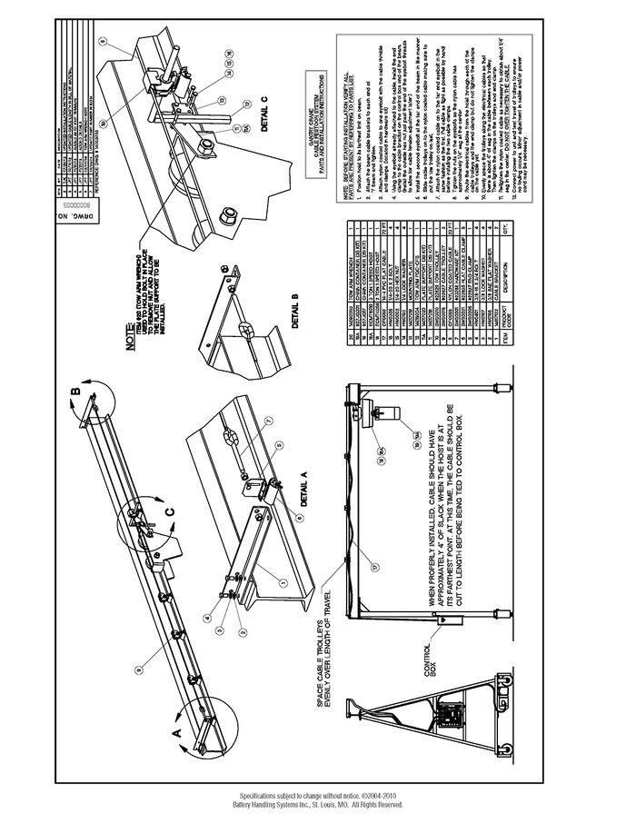
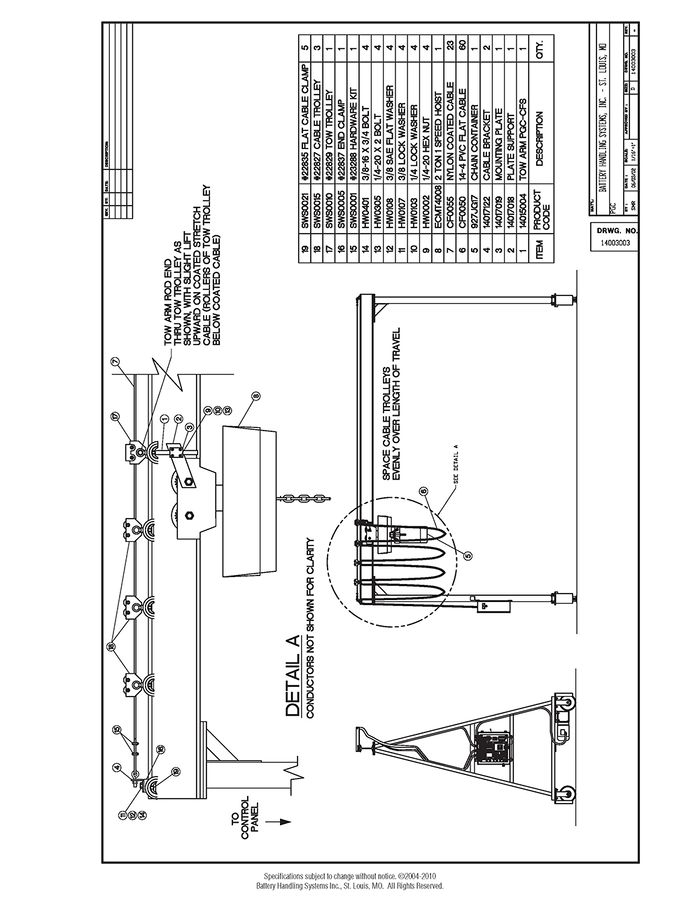
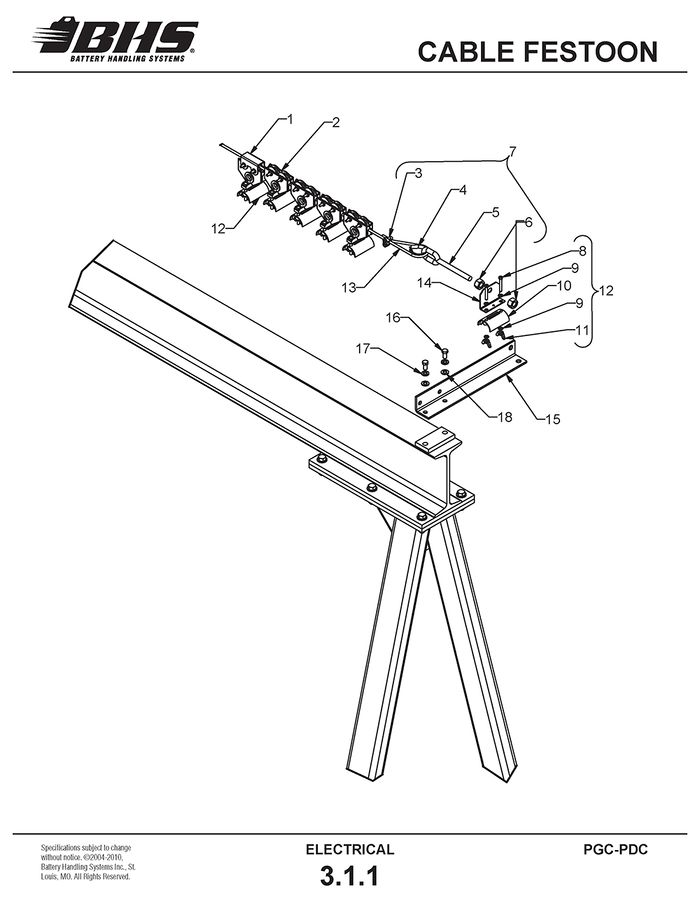
CABLE FESTOON
ITEM | BHS PART NUMBER | DESCRIPTION | NOTES | NO. REQ |
1 | SWS0010 | TROLLEY-CABLE-TOW | 1 | |
2 | SWS0015 | TROLLEY-CABLE | 4 | |
3 | CLAMP-CABLE | INCLUDED WITH SWS0001 | 2 | |
4 | EYELET | INCLUDED WITH SWS0001 | 2 | |
5 | EYE-BOLT | INCLUDED WITH SWS0001 | 2 | |
6 | NUT | INCLUDED WITH SWS0001 | 4 | |
7 | SWS0001 | HARDWARE KIT | 1 | |
8 | BOLT | INCLUDED WITH SWS0021 | 2 | |
9 | FLAT WASHER | INCLUDED WITH SWS0021 | 4 | |
10 | CLAMP | INCLUDED WITH SWS0021 | 1 | |
11 | WING NUT | INCLUDED WITH SWS0021 | 2 | |
12 | SWS0021 | CLIP-CABLE | 6 | |
13 | CF0055 | CABLE | NYLON COATED | AR |
14 | SWS0005 | CLAMP-END-FIXED | 1 | |
15 | 14617122 | BRACKET-CABLE | 2 | |
16 | HW0401 | BOLT-HHCS-3/8-16 X 3/4 | 2 | |
17 | HW0107 | WASHER-LOCK3/8 | 4 | |
18 | HW0108 | WASHER-FLAT-3/8-SAE | 4 |
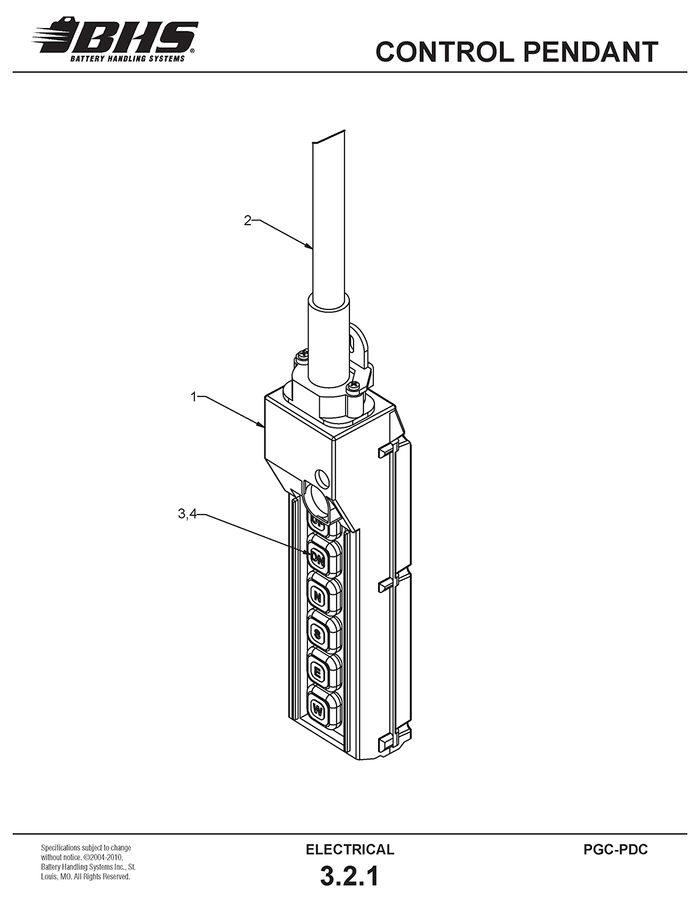
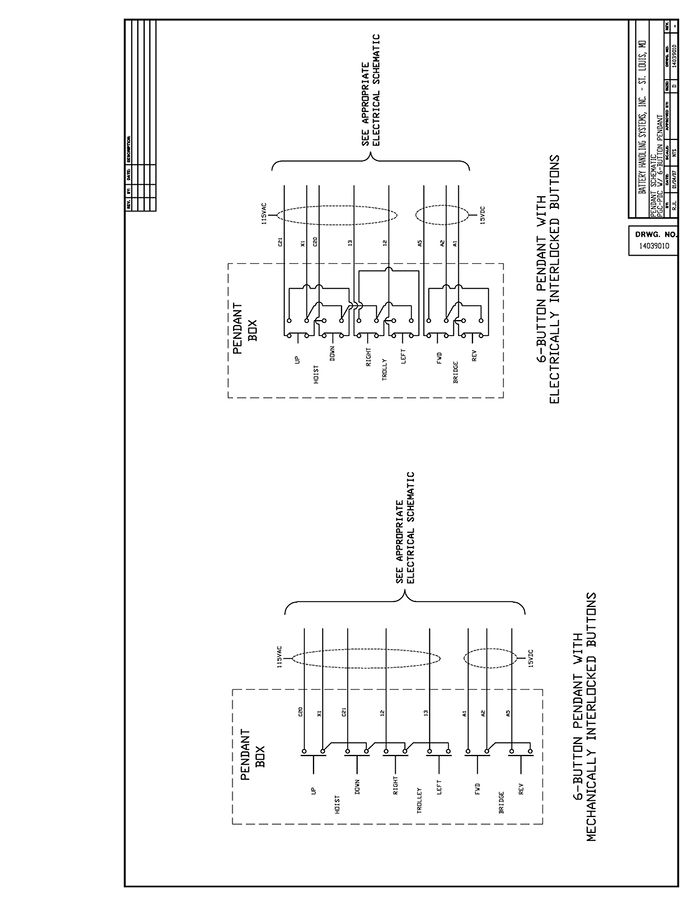
CONTROL PENDANT
ITEM | BHS PART NUMBER | DESCRIPTION | NOTES | NO. REQ |
1 | E0814 | PENDANT-6 BUTTON (YELLOW) | WITH 6' CORD | 1 |
2 | E0518 | 16-10 SO CORD | A/R | |
3 | PB358 | PUSH BUTTON | 6 | |
4 | 536K50 | CONTACT BLOCK | 6 |
ITEM | BHS PART NUMBER | DESCRIPTION | NOTES | NO. REQ |
1 | N/A | PENDANT-6 BUTTON (ORANGE) | DISCONTINUED - MUST ORDER E0814 | - |
2 | E0518 | 16-10 SO CORD | A/R | |
3 | 550-041 | BUTTON COVER W/ LEGEND PLATE KIT | INCL. ALL 6 POSITIONS | 1 |
4 | 550-039 | SWITCH-2 BUTTON-1 SPEED | 3 |
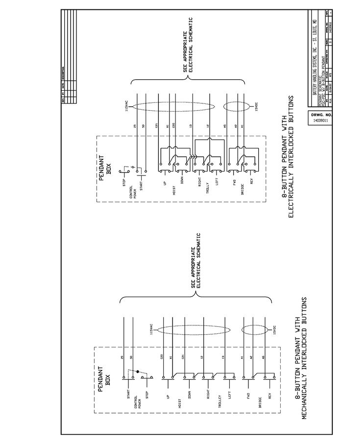
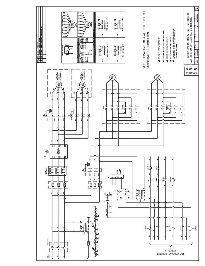
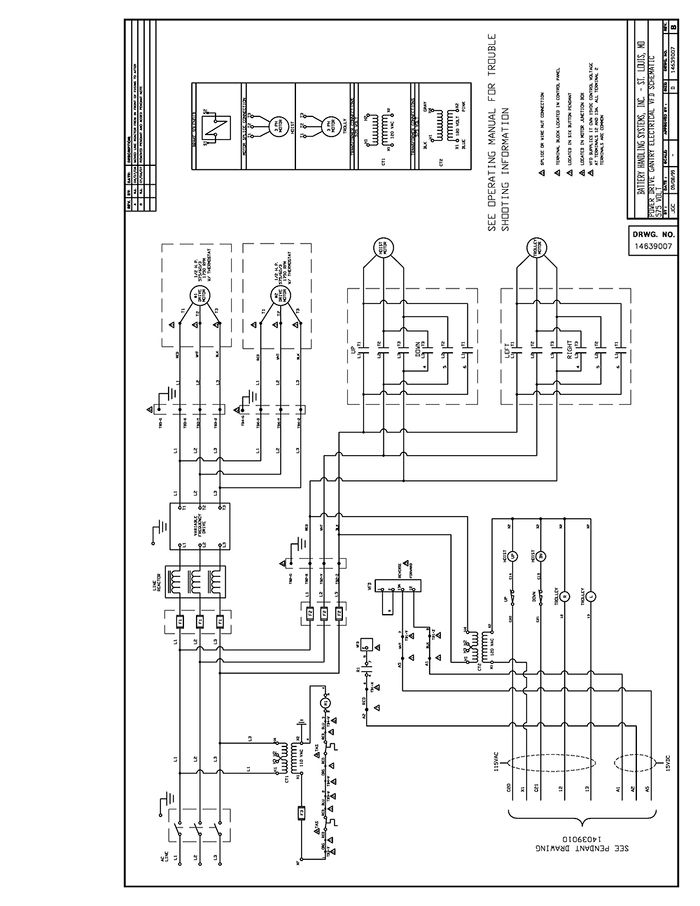
ELECTRICAL SCHEMATICS
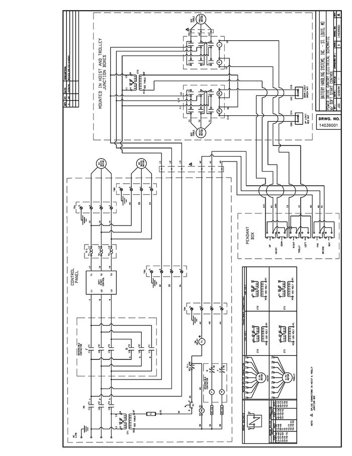
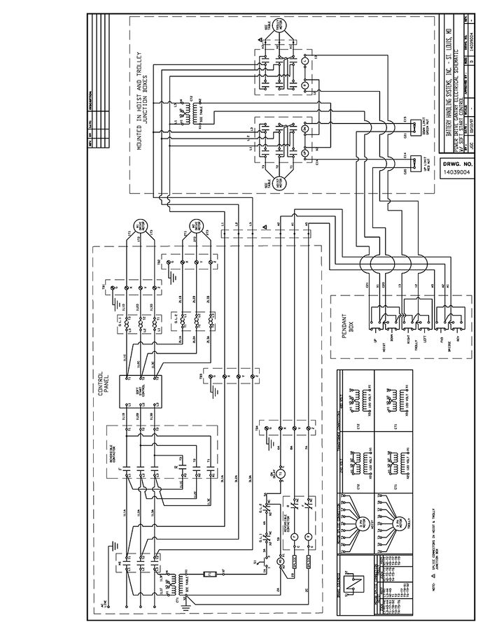
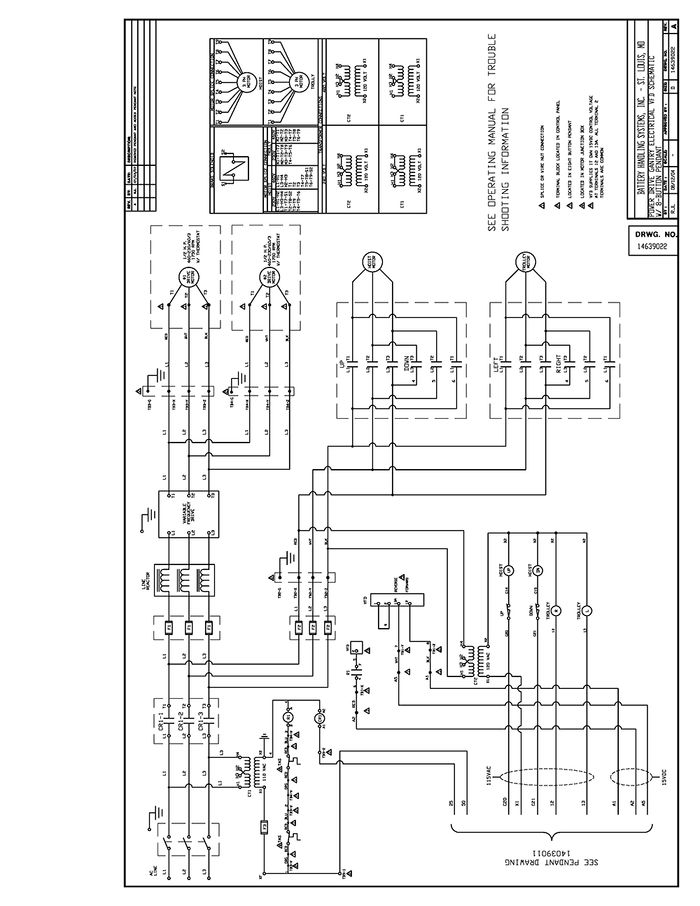
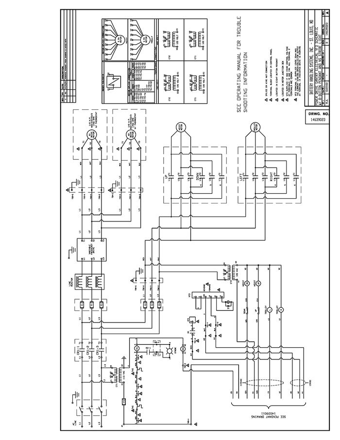
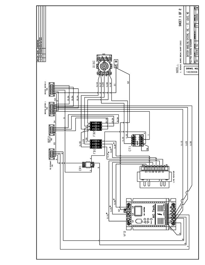
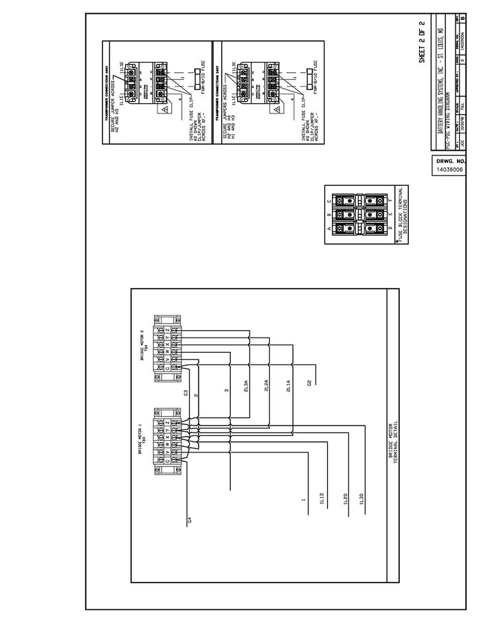
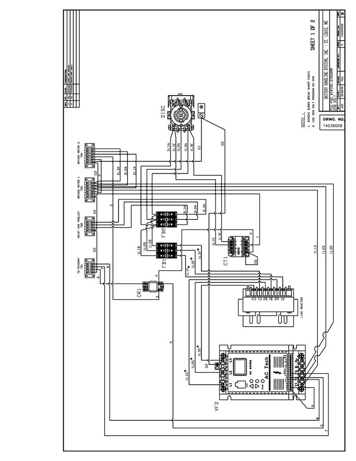
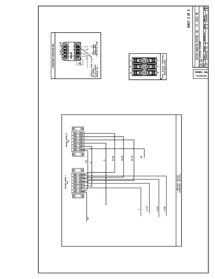
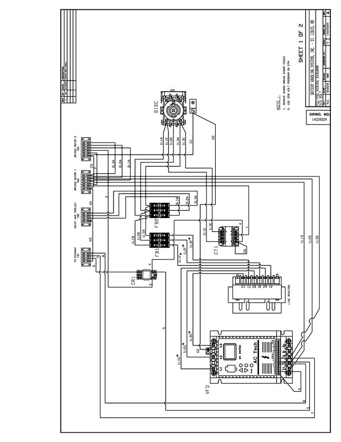
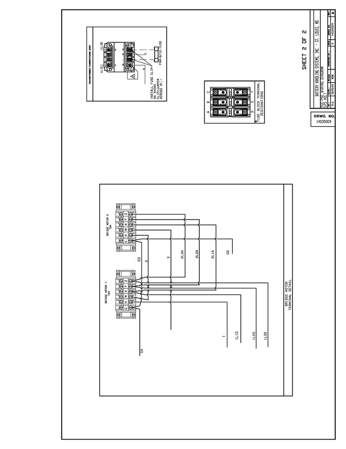
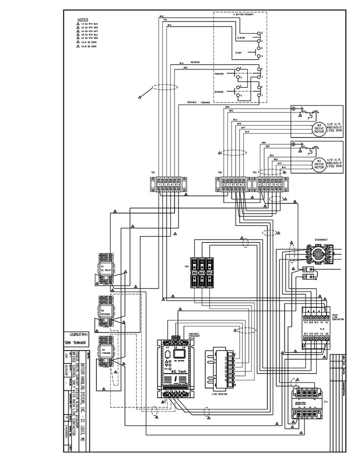
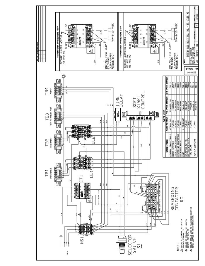
ELECTRICAL WIRING DIAGRAMS
STATEMENT OF WARRANTY
Statement of Warranty
Click here for details on BHS' Statement of Warranty.
