IOM-421 BWC-1
Looking for a specific replacement part? Ctrl-F (or Command-F for Mac users) brings up your browsers search panel and can search any text on the entire web page. Find parts by searching a par t# or part description.
Register your equipment with BHS Optima, BHS's free app.
California Residents: WARNING: This product contains chemicals known to the State of California to cause cancer and/or reproductive harm, and birth defects or other reproductive harm. Learn more here.
Battery Wash Cabinet with Manual Door & Gravity Feed Rollers (BWC-1) Parts & Service Manual
TP-603 - SAFETY AND DE-ENERGIZATION PROCEDURES
GENERAL SAFETY
- Read and understand all instructions and warnings before using or servicing this equipment.
- Keep these instructions for future reference.
- Follow all federal, state and local requirements for handling and treatment of battery wash cabinet effluent.
- Battery Wash Cabinet (BWC) units are not designed to be shipped or transported after initial delivery.
- A licensed structural engineer should be consulted prior to installing a BWC on any building level other than the ground floor.
- Perform system and safety check before operating.
- Failure to follow these instructions and warnings may result in property damage, personal injury or death.
WORK AREA
- Keep work area clean and well lit. Cluttered work areas and poor lighting can lead to accidents.
- Clean up/contain any fluid spills immediately to prevent slips or falls.
- Be aware of potential hazards when performing any service or maintenance to the unit.
SERVICE & MAINTENANCE
Service personnel shall wear Personal Protective Equipment (PPE) appropriate for the task being performed.
LOCKOUT/TAGOUT
Lockout/tagout the BWC per your corporate policy, if damaged or not functioning properly. Lockout/tagout and deenergize all systems prior to performing any maintenance or service to unit.
LEAD-ACID BATTERIES-EXPLOSION HAZARD
Do not allow open flames or sparks of any kind near a battery. Highly explosive gas is generated when charging a battery that can remain in battery cells for extended periods of time after charging is complete.
- Always wear appropriate PPE including rubber apron, gloves, boots and full face shield when performing service or maintenance to any lead-acid batteries.
- Do not place metal or other conductive objects on top of battery. Arcing may occur causing damage to the battery and/or serious personal injury or death.
- Use only chargers matching the voltage and amperage of the battery being charged. Overcharging a battery can cause damage to the battery, charger and/or serious personal injury or death.
- Turn off charger before disconnecting battery from charger. Arcing between battery and charger connectors can cause damage to the connectors and/or serious personal injury or death.
BATTERY WASH WATER HAZARDS
HEAVY METALS:
Battery wash water contains heavy metals including (but not limited to) lead and antimony, which through prolonged exposure can lead to serious, long-term, adverse health conditions.
EXTREME pH LEVELS:
Highly acidic (low pH) as well as highly alkaline/ basic (high pH) solutions can cause severe burns, release toxic fumes, and cause violent chemical reactions when mixed with water or when mixed together.
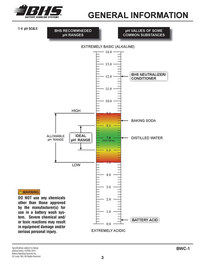
- pH values outside of the BHS allowable range of 5 to 9 should be treated as “extreme” and caution should be taken to avoid direct contact with such solutions.
- Always wear appropriate PPE including rubber apron, gloves, boots and full face shield when working in contact with any battery wash water.
TREATMENT CHEMICALS:
Use of chemicals not approved by BHS to treat wash water may result in the release of toxic fumes.
OPERATIONAL SAFETY
OPERATIONAL SAFETY
- Only personnel trained in the proper and safe operation of BWC units may operate or service the BWC.
- Operators shall wear appropriate PPE suitable for working with industrial lead-acid batteries while operating the BWC (see prior pages).
- All data plates, warning labels, placards, etc. shall be in place and legible at all times. Contact BHS for replacement data plates, warning labels, placards or instructions.
- All users and service personnel shall be familiar with the meaning and risks associated with all data plates, warning labels, etc.
- All operators and service personnel shall be aware of potential crush and shear points while operating or servicing the BWC.
- Keep hands and arms out of the battery compartment while operating the BWC.
- Secure the door in the raised position by way of the door retaining pins prior to performing any service inside the BWC.
- Remove the BWC from service if it is found to be dam-aged, defective, or operating in a hazardous manner (or becomes such while operating) until repairs can be made to correct any problem(s).
DO’s AND DON’T’s
- Disconnect the power before attempting to perform any service or maintenance to the BWC.
- DO NOT exceed the maximum capacity of the BWC.
- DO NOT modify or fi t the BWC with attachments without prior, written approval from BHS.
- DO NOT perform any maintenance or service to the BWC with a battery loaded in the BWC.
- DO NOT allow anyone to enter the BWC at any time unless proper de-energization and lockout/tagout procedures have been performed.
- DO NOT operate the BWC with any guard or cover removed unless required for maintenance or repair.
- DO NOT use the BWC to wash anything other than industrial lead-acid batteries.
- DO NOT use foaming type detergents in conjunction with the BWC.
- DO NOT use soda ash or similar types of neutralizers.
- Use only fully liquefied neutralizers.
- DO NOT use the BWC in a manner for which it is not intended. Some examples of prohibited use are but not limited to:
- As a safety shower
- As a parts washer
- As a storage cabinet
- As a waste water dump from other equipment
- As a battery maintenance/repair station
DE-ENERGIZATION
- Disconnect power to or turn off the RNS supplying the BWC. NOTE: If the BWC is connected directly to a plant water supply, turn the water supply valve off.
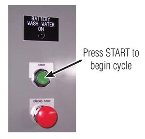
- Cycle the BWC through one complete wash cycle to release the water pressure. See Figure 1.
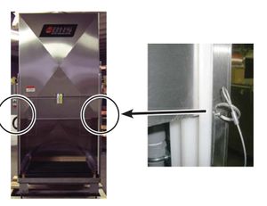
- Raise the door and install the retaining pins to prevent the door from closing. See Figure 2.
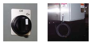
- Turn off and disconnect power to the BWC. See Figure 3.
FIGURE 1
FIGURE 2
FIGURE 3
NOTE: Some acidic water will remain in the BWC sump area as the sump pump will not activate with the RNS power switched off. Refer to BATTERY WASH WATER HAZARDS from above.
GENERAL INFORMATION
FEATURES
- Adjustable wash down timer
- Manual operated automatic door
- Battery drip dry - no air blow-off
AVAILABLE OPTIONS
NC - Neutralizing Cycle at beginning of wash down
FUNCTIONAL DESCRIPTION
CONSTRUCTION:
- Constructed of 304/316 stainless steel sheet and structural shapes.
- All hardware stainless steel or bright galvanized finish.
- All seams welded or sealed for water tight design.
- All welding conforms to all applicable AWS specifications.
- All plumbing components are CPVC Sch 80, brass, nylon, or similar corrosive resistant materials.
WASH CYCLE:
Battery wash down is accomplished via eight, round-pattern spray nozzles mounted on two adjustable height manifolds to accommodate a wide variety of batteries. The wash down is a low pressure - high volume flood wash that removes most dirt, debris and acid residue left on top of the battery from charging. A battery wash cabinet equipped with a neutralizing cycle includes a timed injection of conditioner preset to inject 1.5 oz. of conditioner in 25 seconds. Monitoring the pH of the effluent is required to obtain the optimum timer setting. The recommended pH range is from 5 to 9 with 6 to 8 being ideal.
SPECIFICATIONS
Product Specifications - Imperial / Metric
Frame Construction | 304/316 Stainless Steel |
Air Inlet Size | N/A |
Air Supply Required | N/A |
Air Compressor Required (Minimum Dedicated Use) | N/A |
Air Blow Off Cycle Time | N/A |
Air Nozzle Adjustment | N/A |
No. Air Nozzles | N/A |
Water Inlet Size | 3/4” NPTF |
Water Supply Type Required | 50-80 PSI @ 10 GPM Delivery 3.5 - 5.5 Bar @ 38 LPM Delivery |
Water Nozzle Adjustment | Angle & Height |
No. Water Jets | 8 |
Air Blow Off & Water Line | CPVC Sch 80 Pipe |
Sump Outlet Size | 1” NPTF |
Drain Plug Size | 1” NPTF |
Drain Base Capacity | 36 Gallons / 136 Liters |
Conveyor Drain Base Capacity | N/A |
Input Voltage Required | 120V / 1Ph / 60Hz |
System AMP Draw | <1 Amp |
Control Voltage | 24 Vac |
Door Raise / Lower Mechanism | Manual - Hand Operated |
Wash Cycle Length (Variable Timer) | 10 Sec - 99 Hrs |
No. Rollers Inside Wash Cabinet | 6 Non-Powered Gravity |
Roller Frame Type | Rock Maple Laminate w/ Sealant |
No. Conveyor Rollers | N/A |
Max. Weight Capacity | 4,000 lbs / 1810 kg |
Overall Depth | 62.5” / 1588 mm |
Overall Width | 58.25” / 1480 mm |
Overall Height | 80.125” / 2035 mm Door Lowered 123.75” / 3143 mm Door Raised |
Height from Floor to Top of Roller Bed | 14.75 ± .75” / 375 mm ± 19 mm |
Battery Length | 24” Min / 42” Max 610 mm Min / 1067 mm Max |
Battery Width | 6” Min / 39” Max 152 mm Min / 991 mm Max |
Battery Height | 16” Min / 36” Max 406 mm Min / 914 mm Max |
pH SCALE
INSTALLATION
GENERAL
The following paragraphs provide installation instructions for the BWC. Instructions provided include: unpacking, positioning, power and water installation.
The following tools and materials will be required for system installation:
- Channel-Lock Pliers
- Screw Driver (Standard, 1/4” Blade)
- Adjustable Wrench (12”)
- Measuring Tape (12’ min)
- Level (12”)
- Liquid Neutralizing Conditioner (LNC) (two gallons supplied)
- Ratchet
- 1/2” Socket (to unbolt unit from skid)
Optional:
- Heat Gun (to aid in hose attachment)
UNPACKING
A.) Place packaged system in general area of its operating location. Location considerations should be: within proximity to water supply, electrical power supply, vehicle entrance, battery station locations and applicable building and electrical codes.
B.) Carefully cut and remove the shrink wrap from the unit. Be careful not to scratch, cut or bend any components on system while unpacking.
C.) Inspect the system components for any signs of damage. Take particular note of any evidence of rough handling in transit. Immediately report any damage to shipping agent.
D.) Unbolt the unit from the shipping skid(s).
E.) CAREFULLY lift the BWC from its shipping skids and remove the skid(s) from the area.
F.) Carefully lift the door open using two people and secure the door in the open position using the door support pins. Remove all items shipped inside the BWC, some of which will be used during installation. Once everything has been removed from inside the cabinet, carefully remove the door support pins and lower the door back to the closed position.
POSITIONING
The unit should be positioned to allow adequate clearance in the rear of the cabinet for water and neutralizer (if equipped) connections. Clearance should also be allowed on the left side of the cabinet for electrical hook-up and servicing. The following steps provide instructions for anchoring the BWC.
A.) Move BWC into position allowing clearances previously stated.
B.) Adjust cabinet legs to give the unit a 1/4” rearward pitch to ensure proper wash water drainage to sump area.
C.) Anchor cabinet at each leg.
POWER CABLE CONNECTION
The AC power line must be connected to the unit’s electrical enclosure assembly. The connection should be made by a certified electrician. Ensure that electrical work meets all applicable electrical codes and requirements. See Section 1-3 for BWC power requirements. NOTE: Electrical connections should be appropriate for a wet environment and compliant with a NEMA 12 rating.
NEUTRALIZING CONDITIONER JUG (IF EQUIPPED)
The neutralizer pump must be primed prior to use.
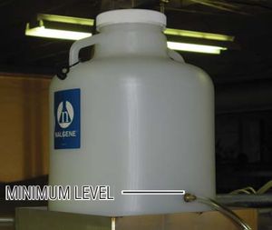
A.) Place the supplied neutralizing conditioner jug on the top, rear of the BWC. See Figure 2-1.
B.) Connect the clear neutralizing conditioner line to the outlet nipple of the conditioner jug. See Figure 2-1.
C.) Fill the jug with conditioner to at least a minimum level of just over the nipple in the jug. See Figure 2-1.
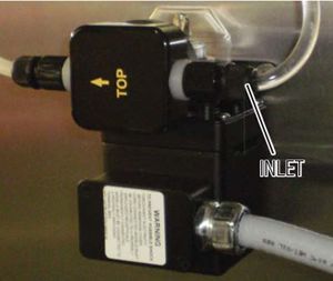
Figure 2-1 D.) Disconnect the conditioner line at the inlet of the neutralizer pump and place the end into a bucket or similar container until conditioner flows from the line. See Figure 2-2
E.) Reconnect the line to the pump inlet and wipe up any spilled neutralizer. See Figure 2--2
Figure 2-2
OPERATION:
- Prepare battery for loading into BWC. Position the extractor so the battery is centered left-to-right with the BWC.
- Align roller height of battery extractor to the height of the BWC rollers.
- Slowly move the battery from the extractor into the BWC.
- Move the extractor away from the BWC.
- Close the BWC door, depress and release the “Start” button. The “Battery Wash Water On” indicator light will illuminate indicating the wash cycle has begin. If the unit is equipped with the “NC” option, neutralizer will be added automatically. The wash cycle will last for approximately 45 seconds and the indicator light will go out indicating the end of the wash cycle.
- Allow the battery to drip dry for a sufficient amount of time to allow all water on the battery case to run off.
- Open the BWC door and reposition the battery extractor with the BWC as done in steps 1 & 2.
- Slowly remove the battery from the BWC onto the battery extractor. NOTE: The longer a battery is allowed to remain inside the BWC after the wash cycle is complete, the more water will be allowed to drain from between the battery cells and out of the bottom of the case. This will reduce the amount of water that will drip on the floor and the extractor.
Ensure the battery cables are positioned on top of the battery so they do not catch on the door or sides of the cabinet when loading and unloading the battery.
PLANT WATER & DRAIN CONNECTION
If the BWC is not being used with an RNS unit (see sect. 2-7), plant If the BWC is not being used with an RNS unit (see sect. 2-7), plant water should be connected via the 3/4” NPTF inlet (located at the water should be connected via the 3/4” NPTF inlet (located at the top-center in the rear of the cabinet). If connections are made to top-center in the rear of the cabinet). If connections are made to plant drains, be sure ALL applicable requirements are met for waste plant drains, be sure ALL applicable requirements are met for waste water treatment prior to discharging effluent. water treatment prior to discharging effluent.
CLOSED-LOOP RECIRCULATION & NEUTRALIZATION SYSTEM (RNS) CONNECTION
Refer to installation instructions supplied with RNS unit (such as BHS models RNS-1, RNS-3-SS or RNS-4-SS) for connections to the BWC.
OPERATION
CONTROLS
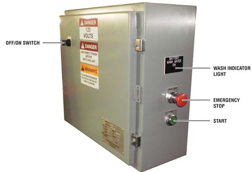
The BWC-1 is operated via controls mounted on the electrical enclosure.
ON/OFF SWITCH - Activates power to the BWC.
START - Initiates the wash cycle.
WASH INDICATOR LIGHT - Illuminates to indicate wash cycle in progress.
EMERGENCY STOP - Immediately stops all functions in the event of a problem.
FIGURE 3-1
OPERATING PROCEDUR
The following procedures will guide the operator through the battery wash process.
OPERATIONAL PRE-CHECK:
The following items should be verified prior to every wash cycle:
- Control panel switch is in the “ON” position.
- Emergency stop is in the reset (pulled out) position.
- Water supply is available:
- If using an RNS system, verify the RNS unit is in the proper mode for use with a BWC unit. Refer to the manual supplied with the RNS unit for the proper operational procedures for that unit.
- If the water supply is connected to plant water, verify the plant water supply valve is open, providing water to the BWC.
- Neutralizer container has at least 1” of solution (if equipped with NC option).
- BWC door is fully open and cabinet has fully drained from previous wash cycle.
NOTE: A small amount of water (1” or less) will remain in the sump area after drainage is complete.
- Sump screen is clear of debris and is properly positioned so that no gaps exist that would allow any debris into the sump area.
OPERATION:
- Prepare battery for loading into BWC. Position the extractor so the battery is centered left-to-right with the BWC.
- Align roller height of battery extractor to the height of the BWC rollers.
- Slowly move the battery from the extractor into the BWC.
- Move the extractor away from the BWC.
- Close the BWC door, depress and release the “Start” button. The “Battery Wash Water On” indicator light will illuminate indicating the wash cycle has begin. If the unit is equipped with the “NC” option, neutralizer will be added automatically. The wash cycle will last for approximately 45 seconds and the indicator light will go out indicating the end of the wash cycle.
- Allow the battery to drip dry for a sufficient amount of time to allow all water on the battery case to run off.
- Open the BWC door and reposition the battery extractor with the BWC as done in steps 1 & 2.
- Slowly remove the battery from the BWC onto the battery extractor. NOTE: The longer a battery is allowed to remain inside the BWC after the wash cycle is complete, the more water will be allowed to drain from between the battery cells and out of the bottom of the case. This will reduce the amount of water that will drip on the floor and the extractor.
Ensure the battery cables are positioned on top of the battery so they do not catch on the door or sides of the cabinet when loading and unloading the battery.
MAINTENANCE
PERIODIC MAINTENANCE & INSPECTION
It is imperative that all equipment be inspected and maintained on a regular basis to ensure proper operation of the BWC.
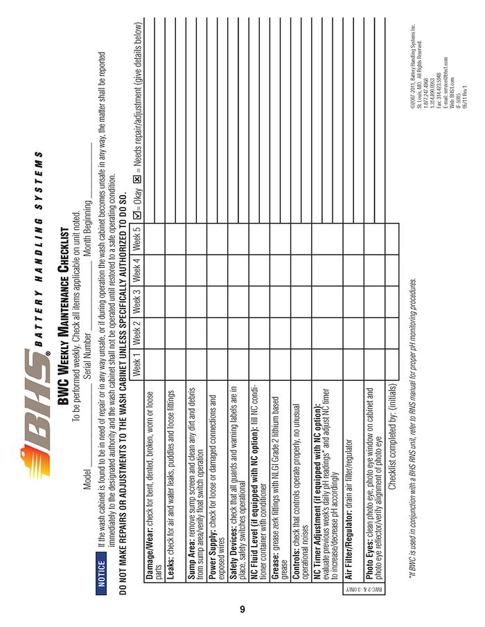
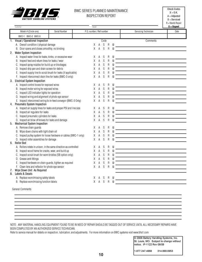
BHS recommends the BWC be inspected and serviced once per week. Use the included form IF-5015 (BWC WEEKLY MAINTENANCE CHECKLIST) as a guide. A complete Preventative Maintenance (P.M.) inspection and servicing should be performed every 3 months. Use the included form IF-1122 (BWC SERIES PLANNED MAINTENANCE INSPECTION REPORT) as a guide.
NOTE: The inspection/maintenance intervals recommended by BHS should be evaluated and adjusted (if needed) based on the actual usage of the wash system as well as the condition of the batteries being serviced.
WEEKLY MAINTENANCE CHECKLIST
PLANNED MAINTENANCE INSPECTION REPORT
TROUBLESHOOTING
SYMPTOM PROBABLE CAUSE CORRECTIVE ACTION | ||
Wash cycle does not be- gin when “START” button is depressed |
|
|
No wash water is being supplied during wash cycle |
|
|
Wash water effluent has consistently too low or too high pH |
|
|
Sump area does not drain |
|
|
STATEMENT OF WARRANTY
Statement of Warranty
Click here for details on BHS' Statement of Warranty.
