(BE-TS) Triple Stack Operator Aboard Battery Extractors – Parts & Service Manual (IOP-401)
Looking for a specific replacement part? Ctrl-F (or Command-F for Mac users) brings up your browsers search panel and can search any text on the entire web page. Find parts by searching a part # or part description.
Register your equipment with BHS Optima, BHS's free app.
California Residents: WARNING: This product contains chemicals known to the State of California to cause cancer and/or reproductive harm, and birth defects or other reproductive harm. Learn more here.
Preface
TP-606 – Safety & De-Energization Procedures
General Safety

|
|
- Battery Extractor (BE) units shall only be operated by suitable persons of at least 18 years of age, who have been trained in the proper and safe operation of the BE and expressly certified/charged, in writing, by the user or their representative.
- Only one person is permitted to travel on the BE at any time.
- BE units shall only be used indoors in an industrial setting on a hard, nonslip, and level floor without defects including but not limited to holes, gouges, cracks, drains or obstacles comprised of concrete or other suitable industrial material meeting the minimum requirements specified by BHS as well as any local requirements.
- A licensed structural engineer should be consulted prior to installing a BE on any building level other than the ground floor.
- BE units are not designed to be shipped or transported after initial delivery.
- Failure to follow these instructions and warnings may result in property damage, personal injury or death.
Work Area
- Keep work area clean and well lit. Cluttered work areas and poor lighting can lead to accidents.
- Clean up/contain any fluid spills immediately to prevent slips or falls.
- Be aware of potential hazards when performing any service or maintenance to the unit.
Service & Maintenance
Service personnel shall wear Personal Protective Equipment (PPE) appropriate for the task being performed.
Operational Safety
- Only personnel trained in the proper and safe operation of BE units may operate or service the BE.
- Operators shall wear appropriate PPE suitable for working with industrial lead-acid batteries while operating the BE (See Lead-Acid Battery Explosion Hazard section).
- All data plates, warning labels, placards, etc. shall be in place and legible at all times. Contact BHS for re-placement data plates, warning labels, placards or instructions.
- All users and service personnel shall be familiar with the meaning and risks associated with all data plates, warning labels, etc.
- All operators and service personnel shall be aware of potential crush and shear points while operating or servicing the BE.
- Keep hands and arms inside the operator compartment while operating the BE.
- Remove BE from service if damaged, defective, or operating improperly (or becomes such while operating) until repairs can be made to correct any problem(s).
- All operators shall be aware of the location of the end stops in the travel path to prevent driving the BE into the end stops.
Do's and Don'ts
- DO NOT exceed the maximum capacity of the BE.
- DO NOT modify or fit the BE with attachments without prior, written approval from BHS.
- DO NOT perform any maintenance or service to the BE with a battery loaded on the BE.
- DO NOT allow anyone to ride in or on the BE.
- DO NOT operate the BE with any guard or cover removed unless required for maintenance or repair.
- Disconnect the BE from all power sources before attempting to perform service or maintenance to the unit.
- DO NOT drive the BE into the end stops.
- DO NOT operate the BE if disengaged from the guidance track.
- DO NOT allow a battery to exit the BE when a lift truck or battery stand is not present to accept the battery.
- DO NOT rotate the arm onto a battery such that any part of the extractor arm, vacuum cup or magnet contacts the top of the battery.
- DO NOT allow anyone to enter the area under the carriage without the service stands properly installed.
- DO NOT use the BE in a manner for which it is not intended. Some examples of prohibited use are but not limited to:
- To transport people
- As a vehicle jack
- To lift loads greater than its rated load capacity
- Where unintentional movement may exist
- Having direct contact with foodstuffs
- In a potentially explosive atmosphere
De-Energization
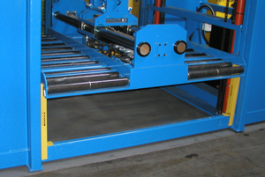
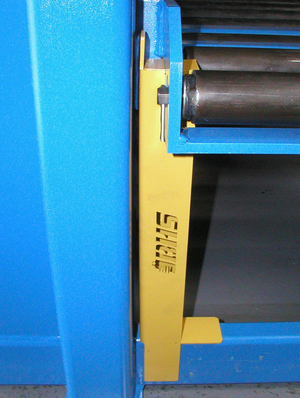
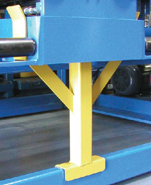
1. Fully lower the BE roller bed or position the roller bed on service stands if service requires the bed be raised. See Figures 1 & 2.
| Failure to properly support the roller bed when performing service under the BE could result in injury from the roller bed lowering unexpectedly. |
|---|
2. Turn key on dashboard to the “OFF” position. See Figure 3.
3. Disconnect power to the extractor or shut off the electrical branch circuit breaker.
| Failure to disconnect electrical power to the BE could result in electrical shock. Serious personal injury or death will occur. |
4. Actuate all hydraulic levers in both directions to re-lease any stored hydraulic pressure. See Figure 4.
Failure to release any stored hydraulic pres-sure could result in injury from:
|
Labels & Placards
Operators should be familiar with the meaning of the following labels and placards found on the BE to ensure proper and safe operation.
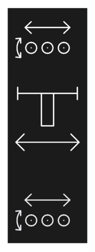
|
Far Power Rollers |
|---|---|
| Arm Travel | |
| Near Power Rollers |

| ||
|---|---|---|
| Drive Forward/Reverse | Platform Raise/Lower | Arm Rotation Near/Far |

|
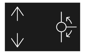
| |
|---|---|---|
| Platform Raise/Lower | Drive Foward/Reverse | Arm Rotation Near/Far |
General Information
Specification Data
| BE-24-2-TS | BE-36-2-TS | BE-42-2-TS | ||
|---|---|---|---|---|
| A | Overall Length | 156.5" | 180.5" | 192.5" |
| B | Overall Width | 72" | 72" | 72" |
| C | Overall Height (Lowered) | 158.188" | 158.188" | 160.688" |
| Overall Height (Raised w/ Overhead Guard) | 182.375" | 182.375" | 182.375" | |
| Overall Height (Raised w/ Strobe & Alarm) | 191.75" | 191.75" | 191.75" | |
| D | Wheel Base | 98" | 122" | 134" |
| E | Drive Wheel Center line | 51" | 51" | 51" |
| F | Battery Compartment Width | 24" | 36" | 42" |
| G | Ground Clearance | .625" | .625" | .625" |
| H | Minimum Roller Height | 6.5" | 6.5" | 6.5" |
| I | Maximum Roller Height | 96" | 96" | 96" |
| J | Operator Platform Height (Lowered/Raised) | 11" / 103" | 11" / 103" | 11" / 103" |
UNITS WITH 10 HP POWER UNIT USED PRIOR TO DECEMBER, 2014
| BE-24-2-TS | BE-36-2-TS | BE-42-2-TS | |
|---|---|---|---|
| Travel Speed | 0 to 190 ft/min / 0 to 0.97 m/s | 0 to 190 ft/min / 0 to 0.97 m/s | 0 to 190 ft/min / 0 to 0.97 m/s |
| Raise - Lower Speed | 0 to 26 ft/min / 0 to 0.13 m/s | 0 to 26 ft/min / 0 to 0.13 m/s | 0 to 26 ft/min / 0 to 0.13 m/s |
| Powered Roller Speed | 0 to 37 ft/min / 0 to 0.19 m/s | 0 to 37 ft/min / 0 to 0.19 m/s | 0 to 37 ft/min / 0 to 0.19 m/s |
| Arm Traverse Speed | 0 to 20 ft/min / 0 to 0.10 m/s | 0 to 20 ft/min / 0 to 0.10 m/s | 0 to 20 ft/min / 0 to 0.10 m/s |
| Arm Rotation Time | 6 s to 8 s | 6 s to 8 s | 6 s to 8 s |
| Draw Bar Pull / Vacuum
(12" / 305 mm Round Cup) |
1,000 lb / 454 kg | 1,000 lb / 454 kg | 1,000 lb / 454 kg |
| Draw Bar Pull Magnet* | 800 lb to 1,200 lb / 363 to 544 kg | 800 lb to 1,200 lb / 363 to 544 kg | 800 lb to 1,200 lb / 363 to 544 kg |
| Vacuum Attach Time | < 1 s | < 1 s | < 1 s |
| Vacuum Release Time | < 1 s | < 1 s | < 1 s |
| Input Voltage | 480 V / 3 ph / 60Hz | 480 V / 3 ph / 60Hz | 480 V / 3 ph / 60Hz |
| AC Current Draw | 16.5 A | 16.5 A | 16.5 A |
| Control Circuit Voltage | 120 V ac | 120 V ac | 120 V ac |
| Hydraulic Power Unit | 10 hp / 7.46 kW | 10 hp / 7.46 kW | 10 hp / 7.46 kW |
| Hydraulic Pump | 16 gal/min / 61 L/min | 16 gal/min / 61 L/min | 16 gal/min / 61 L/min |
| Power Unit | Hydraulic, Variable Displacement | Hydraulic, Variable Displacement | Hydraulic, Variable Displacement |
| Operating Pressure | 1,500 psi / 103 bar | 1,500 psi / 103 bar | 1,500 psi / 103 bar |
| Vacuum Pump | 1/3 hp / 0.25 kW | 1/3 hp / 0.25 kW | 1/3 hp / 0.25 kW |
| Vacuum | 21" Hg / 711 mbar | 21" Hg / 711 mbar | 21" Hg / 711 mbar |
| Full Load Capacity | 10,000 lb / 4535 kg | 10,000 lb / 4535 kg | 10,000 lb / 4535 kg |
| Weight (Empty) | 8,000 lb / 3629 kg | 8,300 lb / 3765 kg | 8,600 lb / 3901 kg |
| Total Compartment Rollers / Powered | 11/5 | 11/5 | 11/5 |
| Guide Track | 3" x 2.5" Angle
76 mm x 64 mm |
3" x 2.5" Angle
76 mm x 64 mm |
3" x 2.5" Angle
76 mm x 64 mm |
| Overall Dimensions (L x W x H) | 156.5" x 72" x 158.188"
3975 mm x 1829 mm x 4018 mm |
180.5" x 72" x 158.188"
4585 mm x 1829 mm x 4018 mm |
192.5" x 72" x 160.688"
4890 mm x 1829 mm x 4081 mm |
| Vacuum Arm Reach | 4.5" to 14" / 114 mm to 356 mm | 4.5" to 14" / 114 mm to 356 mm | 4.5" to 14" / 114 mm to 356 mm |
| Vacuum Arm Reach (Hydraulic Extension) | 9" to 23" / 229 mm to 584 mm | 9" to 23" / 229 mm to 584 mm | 9" to 23" / 229 mm to 584 mm |
| Magnet Arm Reach (Hydraulic Extension) Truck Side | 14" to 22" / 355 mm to 559 mm | 14" to 22" / 355 mm to 559 mm | 14" to 22" / 355 mm to 559 mm |
| Wheel Base | 98" / 2489 mm | 122" / 3099 mm | 134" / 3404 mm |
| Drive Wheel Center Line | 51" / 1295 mm | 51" / 1295 mm | 51" / 1295 mm |
| Battery Compartment Width | 24" / 610 mm | 36" / 915 mm | 42" / 1067 mm |
| Maximum Battery Dimensions
(L x W x H) |
48" x 23" x 34"
1219 mm x 584 mm x 864 mm |
48" x 35" x 34"
1219 mm x 889 mm x 864 mm |
48" x 41" x 34"
1219 mm x 1041 mm x 864 mm |
| Minimum Battery Width
(with vacuum / magnet) |
12" / 305 mm
6" / 152 mm |
12" / 305 mm
6" / 152 mm |
12" / 305 mm
6" / 152 mm |
| Minimum Battery Height | 17.75" / 451 mm | 17.75" / 451 mm | 17.75" / 451 mm |
| Ground Clearance | 0.63" / 16 mm | 0.63" / 16 mm | 0.63" / 16 mm |
| Roller Height | 6.5" Min / 96" Max
165 mm Min / 2438 mm Max |
6.5" Min / 96" Max
165 mm Min / 2438 mm Max |
6.5" Min / 96" Max
165 mm Min / 2438 mm Max |
| NOTES | |||
| Specifications may vary ± 5% because of temperature, floor considerations, and operator efficiency. Values represented under normal operating conditions. | |||
| * Varies with battery case thickness and condition. | |||
UNITS WITH 20 HP POWER UNIT USED DECEMBER, 2014 TO PRESENT
| BE-24-2-TS | BE-36-2-TS | BE-42-2-TS | |
|---|---|---|---|
| Travel Speed | 0 to 240 ft/min / 0 to 1.22 m/s | 0 to 240 ft/min / 0 to 1.22 m/s | 0 to 240 ft/min / 0 to 1.22 m/s |
| Raise - Lower Speed | 0 to 26 ft/min / 0 to 0.13 m/s | 0 to 26 ft/min / 0 to 0.13 m/s | 0 to 26 ft/min / 0 to 0.13 m/s |
| Powered Roller Speed | 0 to 37 ft/min / 0 to 0.19 m/s | 0 to 37 ft/min / 0 to 0.19 m/s | 0 to 37 ft/min / 0 to 0.19 m/s |
| Arm Traverse Speed | 0 to 20 ft/min / 0 to 0.10 m/s | 0 to 20 ft/min / 0 to 0.10 m/s | 0 to 20 ft/min / 0 to 0.10 m/s |
| Arm Rotation Time | 6 s to 8 s | 6 s to 8 s | 6 s to 8 s |
| Draw Bar Pull / Vacuum
(12" / 305 mm Round Cup) |
1,000 lb / 454 kg | 1,000 lb / 454 kg | 1,000 lb / 454 kg |
| Draw Bar Pull Magnet* | 800 lb to 1,200 lb / 363 to 544 kg | 800 lb to 1,200 lb / 363 to 544 kg | 800 lb to 1,200 lb / 363 to 544 kg |
| Vacuum Attach Time | < 1 s | < 1 s | < 1 s |
| Vacuum Release Time | < 1 s | < 1 s | < 1 s |
| Input Voltage | 480 V / 3 ph / 60Hz | 480 V / 3 ph / 60Hz | 480 V / 3 ph / 60Hz |
| AC Current Draw | 35 A | 35 A | 35 A |
| AC Current Draw w/ Electric Drive Option | 42 A | 42 A | 42 A |
| Control Circuit Voltage | 120 V ac | 120 V ac | 120 V ac |
| Hydraulic Power Unit | 20 hp / 14.9 kW | 20 hp / 14.9 kW | 20 hp / 14.9 kW |
| Hydraulic Power Unit w/ Electric Drive Option | 25 hp / 18.7 kW | 25 hp / 18.7 kW | 25 hp / 18.7 kW |
| Hydraulic Pump | 22 gal/min / 83 L/min | 22 gal/min / 83 L/min | 22 gal/min / 83 L/min |
| Power Unit | Hydraulic, Variable Displacement | Hydraulic, Variable Displacement | Hydraulic, Variable Displacement |
| Operating Pressure | 1,500 psi / 103 bar | 1,500 psi / 103 bar | 1,500 psi / 103 bar |
| Vacuum Pump | 1/3 hp / 0.25 kW | 1/3 hp / 0.25 kW | 1/3 hp / 0.25 kW |
| Vacuum | 21" Hg / 711 mbar | 21" Hg / 711 mbar | 21" Hg / 711 mbar |
| Full Load Capacity | 10,000 lb / 4535 kg | 10,000 lb / 4535 kg | 10,000 lb / 4535 kg |
| Weight (Empty) | 8,000 lb / 3629 kg | 8,300 lb / 3765 kg | 8,600 lb / 3901 kg |
| Total Compartment Rollers / Powered | 11/5 | 11/5 | 11/5 |
| Guide Track | 3" x 2.5" Angle
76 mm x 64 mm |
3" x 2.5" Angle
76 mm x 64 mm |
3" x 2.5" Angle
76 mm x 64 mm |
| Overall Dimensions (L x W x H) | 156.5" x 72" x 158.188"
3975 mm x 1829 mm x 4018 mm |
180.5" x 72" x 158.188"
4585 mm x 1829 mm x 4018 mm |
192.5" x 72" x 160.688"
4890 mm x 1829 mm x 4081 mm |
| Vacuum Arm Reach | 4.5" to 14" / 114 mm to 356 mm | 4.5" to 14" / 114 mm to 356 mm | 4.5" to 14" / 114 mm to 356 mm |
| Vacuum Arm Reach (Hydraulic Extension) | 9" to 23" / 229 mm to 584 mm | 9" to 23" / 229 mm to 584 mm | 9" to 23" / 229 mm to 584 mm |
| Magnet Arm Reach (Hydraulic Extension) Truck Side | 14" to 22" / 355 mm to 559 mm | 14" to 22" / 355 mm to 559 mm | 14" to 22" / 355 mm to 559 mm |
| Wheel Base | 98" / 2489 mm | 122" / 3099 mm | 134" / 3404 mm |
| Drive Wheel Center Line | 51" / 1295 mm | 51" / 1295 mm | 51" / 1295 mm |
| Battery Compartment Width | 24" / 610 mm | 36" / 915 mm | 42" / 1067 mm |
| Maximum Battery Dimensions
(L x W x H) |
48" x 23" x 34"
1219 mm x 584 mm x 864 mm |
48" x 35" x 34"
1219 mm x 889 mm x 864 mm |
48" x 41" x 34"
1219 mm x 1041 mm x 864 mm |
| Minimum Battery Width
(with vacuum / magnet) |
12" / 305 mm
6" / 152 mm |
12" / 305 mm
6" / 152 mm |
12" / 305 mm
6" / 152 mm |
| Minimum Battery Height | 17.75" / 451 mm | 17.75" / 451 mm | 17.75" / 451 mm |
| Ground Clearance | 0.63" / 16 mm | 0.63" / 16 mm | 0.63" / 16 mm |
| Roller Height | 6.5" Min / 96" Max
165 mm Min / 2438 mm Max |
6.5" Min / 96" Max
165 mm Min / 2438 mm Max |
6.5" Min / 96" Max
165 mm Min / 2438 mm Max |
| NOTES | |||
| Specifications may vary ± 5% because of temperature, floor considerations, and operator efficiency. Values represented under normal operating conditions. | |||
| * Varies with battery case thickness and condition. | |||
Pre-Installation Check
Floor Conditions
The floor is the single most critical area of the battery room. A bad floor can cause significant issues with the installation as well as downtime and maintenance problems with the extractor. The floor should be verified as to its minimum thickness and strength with user. As noted on the drawing, the specific requirement of flatness for your particular type of system is listed. Below is a chart stating floor requirements. If possible, especially on double stack and higher systems, a digital level should be used to shoot the grade for compliance with the specification. The floor should also be inspected for severe cracks or excessively wide expansion joints in the travel path of the machine. If floor drains are present, they must not have a grade to the opening that encroaches into the travel path.
F-min is a rating method used to evaluate the flatness and levelness of a floor designated as "defined travel path". For example, an F-min rating of 60 means that there is no more than .129" of variation in the transverse axis (wheels left to right) and .287" variation in the longitudinal axis (front to back) on the equipment.
To avoid potential damage to drive wheel assemblies, guide track, structural components, guide rollers and issues with the inner frame equalization the "defined travel path" of the Battery Extractor should meet or exceed the recommended F-min specification. See chart below for the model specifications.
| Model | F-Min | +/- Longitudinal | +/- Transverse | Slope Defect |
|---|---|---|---|---|
| SL, DS | 40 | .287" | .192" | .096" |
| TS | 60 | .186" | .129" | .066" |
| QS | 85 | .131" | .091" | .047" |
Operating Controls & Instructions
Operator Console
NOTE: Safety devices for the machine and the machine operating area SHALL NOT be rendered inoperable or misused.
Typical BE-TS operator console shown above. Position of optional controls may vary from that shown depending on age of unit and/or combination of optional controls present.
HMI display standard on units shipped after February, 2020 for Industrial Internet of Things (IIoT) package.
Safety Features
Key Switch – Located on the dash (see above). Primary on/off switch to prevent unauthorized personnel from operating the BE.
Emergency Stop – Located on the dash (see above). Will stop all functions immediately, locking all hydraulics in place. To use, press down on the red button. The machine key must be used to reset the emergency stop.
Foot Switch – Must be depressed to operate the BE. Stepping off the foot switch will stop all functions immediately, locking all hydraulics in place. To resume use, depress the foot switch.
Gate Switch – The gate must be fully closed for the BE to operate.
Extractor Arm Switch – Does not permit the machine to move forward or backward unless the extractor arm is located in the center of the carriage between the indicating arrows located on the arm guard.
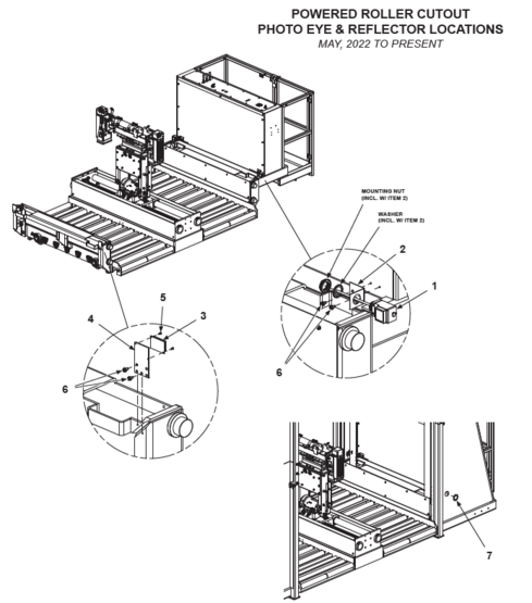
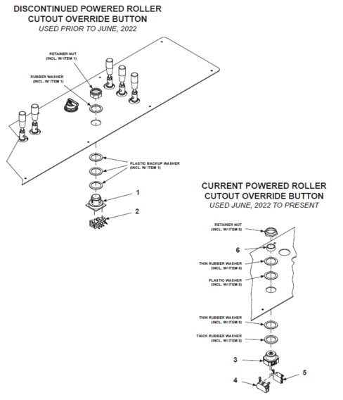
Powered Roller Cutout (PRC-1 or PRC-2) (if equipped) – Disengages the powered roller function when the photo eye positioned on the edge of the BE battery compartment is disrupted by a battery, requiring additional input from the operator. Pressing the "Power Roller Cutout" override button (see above) on the dash will resume powered roller operation when loading or unloading batteries from the BE carriage.
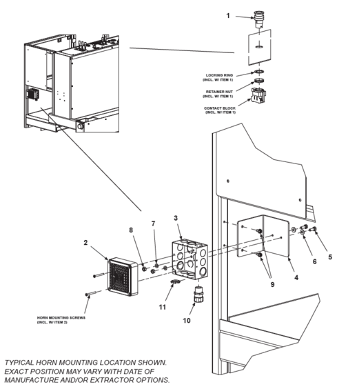
Horn (If equipped) – Button located on the dash (see above). Used to alert personnel before moving the BE.
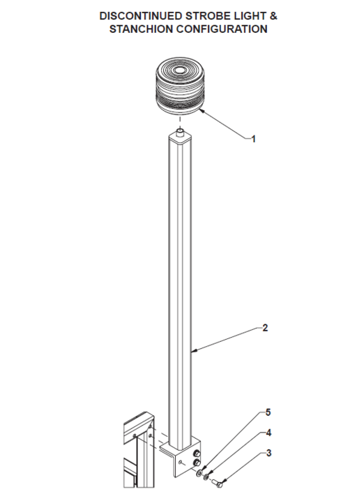
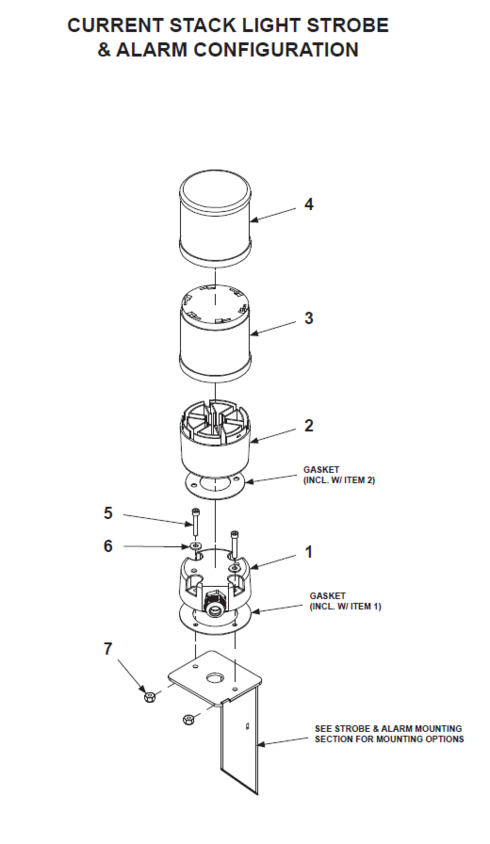
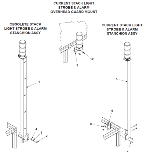
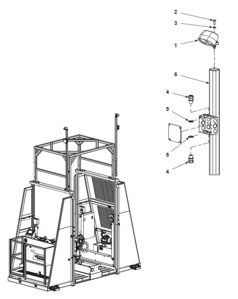
Strobe Light (If equipped) – Located on a vertical stanchion mounted to the right rear of the operator compartment. For units equipped with optional overhead guard (OHG), the beacon is located above of the operator compartment. Beacon automatically flashes when the BE is switched on to visually notify the BE is in use.
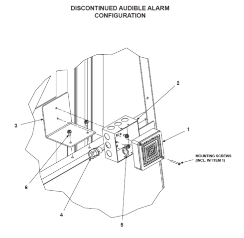
Audible Alarm (if equipped) – Mounted in the same location as the Strobe Light. Automatically sounds when the BE is switched on to notify personnel that the BE is in use.
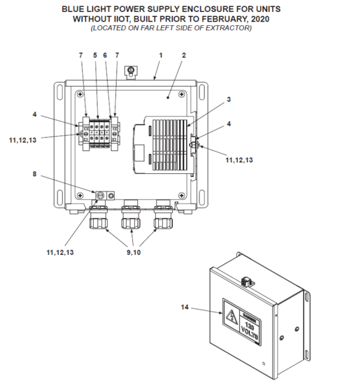
Blue Light (if equipped) - Mounted at an elevated position on either end of the extractor which project a bright, highly concentrated blue beam pattern on the ground visually alerting personnel to the direction the extractor is moving.
Operation Overview
- All operators should be familiar with the operator console of the extractor before performing any battery changes. The controls of the console are simple and well marked. It consists of six, manually operated, hydraulic control valves and a three position selector switch which controls the left and right vacuum cups (or optional magnets).
- The operator shall make certain there are no persons or obstacles in the extractor path prior to traveling forward or reverse.
- All manual valves are moved in the direction of the function travel which it controls with exception of the lift/lower valve, which is pulled toward the operator for "up" and pushed away for "down."
- In the event of any failure or malfunction, step off the dead-man switch or press the E-stop button and all functions will stop immediately, locking all hydraulics in place.
- The extractor arm must be in the center of the carriage or the unit will not travel forward or reverse.
- To ensure smooth operation, all valve movements should be made in a slow, deliberate motion.
- Only one key should be provided to operate the extractor.
- When leaving the machine, the operator shall turn off the key switch, remove the key and logout out of the IIoT (if equipped) to prevent unauthorized use
- Ensure all the batteries and cables are properly stored in the battery stands prior to moving the BE.
- The BE is designed to carry only one battery in each compartment on the carriage.
- When loading the BE, position the batteries in the center of the compartments on the powered rollers to prevent any battery movement when transporting.
- Ensure there are no projections outside of the carriage before moving the BE.
Operating Instructions
Pre-Change Out Preparation
1. Position lift truck for change out in designated area.
2. Remove all battery restraints and disconnect battery cables following manufacturers guidelines. (Be sure to position battery cables so as not to be damaged by the battery during change out.)
3. Board battery extractor and close safety gate. (Gate must be fully closed or unit will not operate.)
4. Turn key switch to "ON" position.
5. Log in on the HMI display (if equipped with BE-IIoT package).
6. Depress foot pedal.
Discharged Battery Removal
1. Move extractor forward or reverse to position center of empty compartment with center of lift truck battery compartment. (Lead roller of extractor is equipped with a centering groove. Users may find it beneficial to mark center of lift truck compartment to aid in alignment.)
2. Align extractor's roller compartment height with lift truck's battery compartment.
3. Rotate extractor arm into battery compartment aligned in Step 2.
4. Move extractor arm toward battery until vacuum cup/magnet contacts battery.
![]() DO NOT force cup/magnet into battery after initial contact with battery is made.
DO NOT force cup/magnet into battery after initial contact with battery is made.
5. Energize vacuum/magnet by turning selector switch to proper direction, left or right.
6. Move extractor arm away from lift truck toward center of extractor roller bed, removing discharged battery. (Battery should be pulled past first three idler rollers onto first or second powered roller.)
7. Turn off vacuum/magnet and move extractor arm away from battery 1" to 2".
8. Rotate extractor arm out of battery compartment into opposite compartment (if empty) and center arm in carriage.
9. Move battery into center of compartment using powered rollers.
Charged Battery Retrieval
1. Locate charged battery for appropriate type of lift truck being changed.
2. Raise battery extractor roller compartment to proper level to gain access as needed to disconnect desired battery from its charger and disengage battery safety stop.
![]() ALWAYS be sure charging has been completed and charger is not still charging battery. Dangerous sparking/arcing can occur if battery is unplugged from charger while charging.
ALWAYS be sure charging has been completed and charger is not still charging battery. Dangerous sparking/arcing can occur if battery is unplugged from charger while charging.
3. Move extractor to appropriate rack position and align empty roller compartment with the center of the battery storage rack compartment. (The battery safety stop of each compartment is the center of that compartment and should be used for alignment with the groove in the lead roller of the battery extractor compartment.)
4. Rotate arm into empty compartment (if not already positioned there.)
5. Move extractor arm toward battery until vacuum cup/magnet contacts battery.
6. Energize vacuum cup/magnet by turning selector switch to proper direction, left or right.
![]() DO NOT force cup/magnet into battery after initial contact with battery is made.
DO NOT force cup/magnet into battery after initial contact with battery is made.
7. Move extractor arm away from battery rack toward center of extractor roller bed, removing charged battery. (Battery should be pulled past first three idler rollers onto first or second powered roller.)
8. Turn off vacuum/magnet and move extractor arm away from battery 1" to 2".
9. Rotate extractor arm out of battery compartment into fully vertical position.
10. Move battery into center of compartment using powered rollers.
Discharged Battery Return
1. If required, adjust extractor compartment height to battery rack level with open battery compartment. Drive extractor to align roller compartment containing discharged battery with open battery compartment.
2. Return discharged battery to battery rack using powered rollers.
NOTE: In most instances, batteries can be deposited into battery racks in one motion using only powered rollers. When this does not work, the battery may need slight assistance from extractor arm. To do this, rotate arm into compartment such as one would if removing battery from rack. If extractor is vacuum equipped, position top edge of cup slightly higher than edge of battery (or over lifting eye if so equipped) to prevent cup from adhering to battery - No vacuum/magnet is necessary for pushing. DO NOT activate vacuum/magnet switch. Slowly push battery into rack until fully into compartment.
3. Engage battery safety stop and connect battery to charger as required.
Charged Battery Installation
1. Lower extractor to fully lowered position.
2. Drive extractor back to lift truck and align roller compartment containing charged battery as performed in steps 1 and 2 of "Discharged Battery Removal".
3. Move charged battery toward lift truck compartment by using powered rollers, verifying precise battery alignment.
![]() Many batteries are a tight fit into lift truck battery compartments. Care MUST be taken to ensure alignment is precise to avoid damage to battery, lift truck, and/or battery extractor.
Many batteries are a tight fit into lift truck battery compartments. Care MUST be taken to ensure alignment is precise to avoid damage to battery, lift truck, and/or battery extractor.
4. Adjust extractor vertically as well as horizontally, if needed
5. Insert battery into lift truck as far as possible using only the powered rollers.
6. Rotate extractor arm into compartment and SLOWLY push battery into lift truck. (Be sure to watch battery cables for interference.)
7. Return extractor arm to center of roller bed and lower extractor to fully lowered position. Drive extractor out of immediate area.
8. Turn off key switch, remove key from switch, log out on the HMI display (if equipped with BE-IIoT package) and carefully exit extractor.
9. Secure newly installed battery in lift truck and reconnect battery cables.
10. Return lift truck to service
Optional Powered Roller Cutout Operation
Units equipped with optional Powered Roller Cutout, the powered roller override button must be depressed in addition to actuating the hydraulic valve when a battery disrupts the photo eye(s) at the edge of the battery compartments while using the powered rollers to transfer batteries on and off of the battery extractor.
IIoT Equipped Units
Units shipped after February, 2020 are equipped with BE-IIoT (Industrial Internet of Things) package. Operators must log in to the BE-IIoT system using the HMI (Human Machine Interface) display located on the dashboard to operate the extractor.
When finished operating the extractor, the operator should log out of the BE-IIoT to prevent unauthorized access and/or operation of the extractor.
Manual Unloading
Lockout/tagout and de-energize all equipment prior to manually unloading any battery.
In the event of power loss or an operational malfunction of the BE not allowing a battery to be unloaded using normal operating procedures, it is recommended a battery be removed from the BE using certified and approved vertical extraction methods and devices.
| Read, understand and observe all safety warnings and procedures related to the vertical extraction device(s) being used. |
Should the status of the BE not allow for safe vertical extraction (due to position in the battery aisle or level of the inner carriage), only repairs required to safely maneuver the BE to a position allowing for safe vertical extraction should be made. Once any batteries are safely unloaded, any remaining repairs can be made.
Spare Parts List
Use only BHS approved replacement parts.
Refer to the appropriate Spare Parts Kit (vacuum equipped units - Pt# BE-SPKV-TS, magnet equipped units - Pt# BE-SPKM-TS) for the list of items recommended by BHS to have on hand for BE-TS models to minimize any downtime due to minor breakdowns that may occur under normal operating conditions.
BHS offers many replacement parts kits containing relevant or related parts when replacing certain individual parts or replacing any obsolete / upgraded parts.
BHS also offers a supplement hose kit (Pt# 80342003) which contains an assortment of hoses allowing any hose on the extractor to be replaced immediately with a temporary hose of equal length or longer. After the extractor is back up and running, the failed hose can be taken to have an exact replacement made. Once the new hose is made and installed, the temporary hose can be returned to the kit for future use.
Go to www.bhs1.com and click "Parts" for all the latest parts kits and corresponding installation instructions (if applicable).
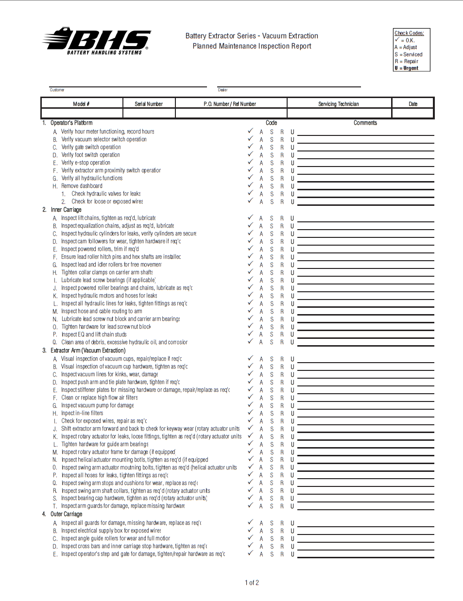
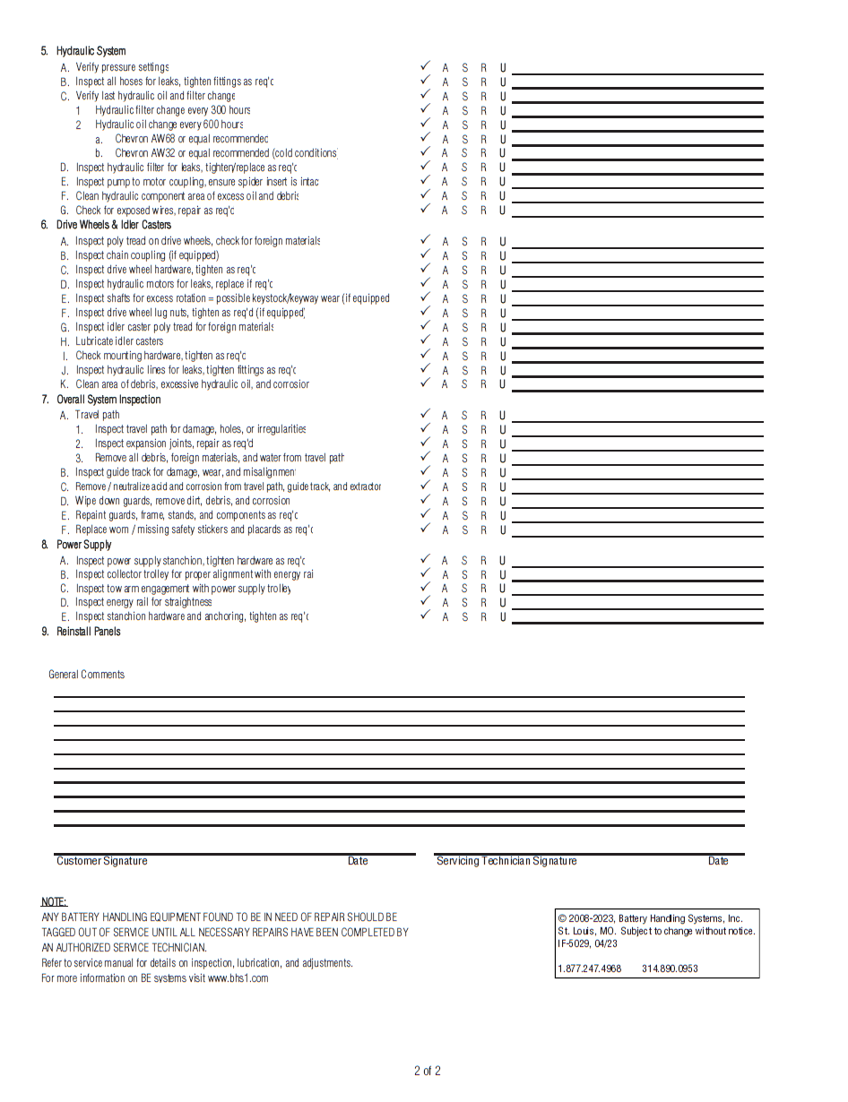
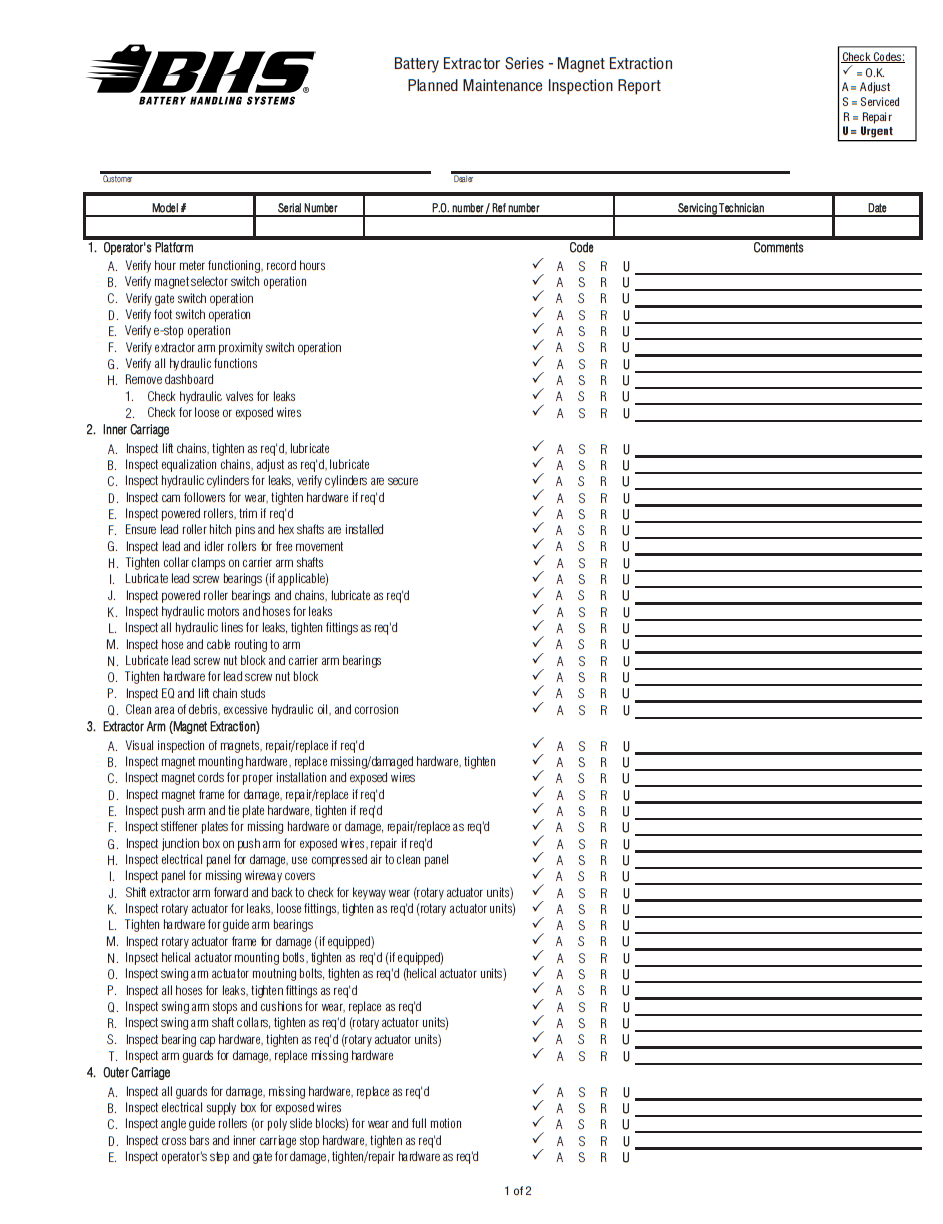
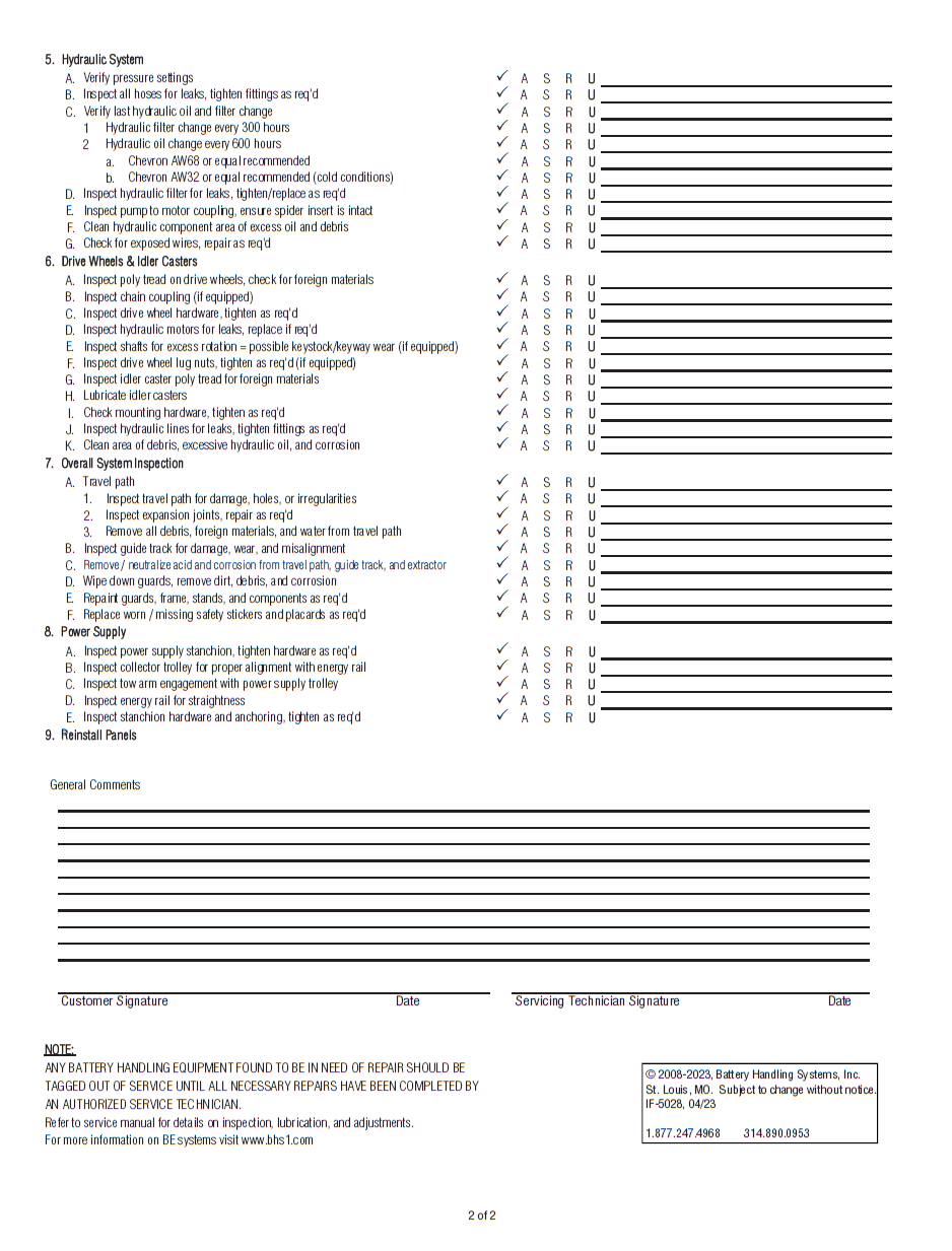
BHS recommends that a full maintenance inspection report similar to the one provided be done at least once a month.
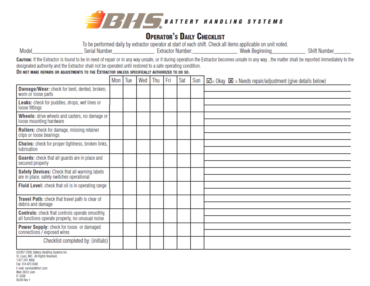
Any parts found to be excessively worn or damaged should promptly be replaced unless said parts pose a safety risk to the operator and/or extractor, in which case the unit should be removed from service until the problem(s) are remedied (See
Operator's Daily Checklist.)
Note: Spare parts kits contain parts for the most current machine design/configuration. Due to continuous design and manufacturing updates and improvements, not all the parts in the spare parts kits may be compatible with older units. Consult factory when ordering spare or replacement parts for existing units in the field to ensure part compatibility.
Parts Sections
Chassis
Equalization Components
| ITEM | BHS PART NUMBER | DESCRIPTION | REF. KIT NO. | NOTES | NO. REQ |
|---|---|---|---|---|---|
| 1 | PT0222-1 | LINK-CONNECTING-#60 | 8 | ||
| 2 | HW0017 | NUT-HEX-3/4-10 | 8 | ||
| 3 | HW0115 | WASHER-LOCK-3/4" | 4 | ||
| 4 | 43097001 | STUD-ANCHOR-5" | Upper | 4 | |
| 5 | HW0020 | NUT-JAM-3/4-10 | 4 | ||
| 6 | 43097002 | STUD-ANCHOR-2" | Lower | 4 | |
| 7 | 00158001-14 | CHAIN-ROLLER-#60 | 4 |
| ITEM | BHS PART NUMBER | DESCRIPTION | REF. KIT NO. | NOTES | NO. REQ |
|---|---|---|---|---|---|
| 1 | PT0416 | COLLAR-SHAFT-1 1/2" | 4 | ||
| 2 | 43097006 | KEY-3/8" X 2 3/4" | 4 | ||
| 3 | PT0224 | SPROCKET-60B12 X 1 1/2" | Keyed in line | 8 | |
| 4 | PT0405 | FLANGE BEARING-2 BOLT-1 1/2" | 4 | ||
| 5 | HW0502 | BOLT-HHCS-1/2-13 X 1 1/4" | 8 | ||
| 6 | HW0110 | WASHER-LOCK-1/2" | 8 | ||
| 7 | 43127001 | SHAFT-EQUALIZATION-81.75" | BE-24-2-TS | 2 | |
| 43327001 | SHAFT-EQUALIZATION-105.75" | BE-36-2-TS | 2 | ||
| 44327001 | SHAFT-EQUALIZATION-117.75" | BE-42-2-TS | 2 | ||
| 44527001 | SHAFT-EQUALIZATION-75.75" | BE-42-1-TS | 2 | ||
| 8 | PT0503 | BEARING-FLANGED LOAD-2 1/4" | Used after December 2003 | 8 | |
| 43026001 | BEARING-FLANGED LOAD-2 1/4" (MACHINED) | Used prior to December 2003 | 8 | ||
| 9 | HW0025 | NUT-JAM-7/8-14 | 8 | ||
| 10 | HW0117 | WASHER-LOCK-7/8" (NOT SHOWN) | Used prior to August 2002 | 8 |
Bridge & Cross Bar
| ITEM | BHS PART NUMBER | DESCRIPTION | REF. KIT NO. | NOTES | NO. REQ |
|---|---|---|---|---|---|
| 1 | HW0502 | BOLT-HHCS-1/2-13 X 1 1/4" | 12 | ||
| 2 | HW0110 | WASHER-LOCK-1/2" | 20 | ||
| 3 | HW0112 | WASHER-FLAT-1/2"-SAE | 20 | ||
| 4 | HW0515 | BOLT-HHCS-1/2-13 X 2" | Fully Threaded | 8 | |
| 5 | HW0007 | NUT-HEX-1/2-13 | 8 |
Lift Cylinder Connections
| ITEM | BHS PART NUMBER | DESCRIPTION | REF. KIT NO. | NOTES | NO. REQ |
|---|---|---|---|---|---|
| 1 | 00158001-13 | CHAIN-ROLLER-#80 | 4 | ||
| 2 | HW0014 | NUT-HEX-1-8 | 8 | ||
| 3 | 43897002 | STUD-LIFT-INNER FRAME | 4 | ||
| 4 | PT0204 | LINK-CONNECTING-#80 | 8 | ||
| 5 | 43897001 | STUD-LIFT-OUTER FRAME | 4 | ||
| 6 | 43815018 | BRACKET-CYLINDER SUPPORT | 4 | ||
| 7 | SS0761 | U-BOLT-CYLINDER MOUNTING | 4 | ||
| 8 | HW0108 | WASHER-FLAT-3/8"-SAE | 12 | ||
| 9 | HW0107 | WASHER-LOCK-3/8" | 12 | ||
| 10 | HW0005 | NUT-HEX-3/8-16 | 8 | ||
| 11 | HW0514 | BOLT-HHCS-1/2-13 X 2 1/2" | Idler caster end of unit | 2 | |
| HW0504 | BOLT-HHCS-1/2-13 X 2" | Drive wheel end of unit | 2 | ||
| 12 | HW0110 | WASHER-LOCK-1/2" | 4 | ||
| 13 | HW0112 | WASHER-FLAT-1/2"-SAE | 4 | ||
| 14 | HW0402 | BOLT-HHCS-3/8-16 X 1" | 4 | ||
| 15 | 43822002 | CLEVIS ASSEMBLY | Sold as assembly only | 4 |
Guidance Arm
| ITEM | BHS PART NUMBER | DESCRIPTION | REF. KIT NO. | NOTES | NO. REQ | |
|---|---|---|---|---|---|---|
| 1 | 43015011 | GUIDE ARM WELDMENT, 2 ROLLER | 2 | - | ||
| 2 | 43017025 | SPACER-GUIDE ARM | † 1/2" thick | 4 | - | |
| 3 | 41215204 | GUIDE ARM WELDMENT, 4 ROLLER | - | 2 | ||
| 4 | 41217274 | SPACER-GUIDE ARM | - | 4 | ||
| 5 | 43012007 | CAM ROLLER-1 3/4" | 4 | 8 | ||
| 6 | HW0115 | WASHER-LOCK-3/4" | 4 | 8 | ||
| 7 | HW0011 | NUT-HEX-3/4-16 | 4 | 8 | ||
| 8 | HW0509 | BOLT-HHCS-1/2-13 X 4-1/2" | 4 | 6 | ||
| 9 | HW0112 | WASHER-FLAT-1/2"-SAE | 4 | 6 | ||
| 10 | HW0110 | WASHER-LOCK-1/2" | 4 | 6 | ||
| 11 | HW0007 | NUT-HEX-1/2-13 | 4 | 6 | ||
| 12 | 41215234 | GUIDE ARM WELDMENT (POLY) | 2 | - | ||
| 13 | 41217317 | POLY SLIDE MOUNTING BLOCK | 4 | - | ||
| 14 | 41217318 | POLY SLIDE | 4 | - | ||
| 15 | HW0501 | BOLT-HHCS-1/2-13 X 1" | 12 | - | ||
| 16 | HW0110 | WASHER-LOCK-1/2" | 12 | - | ||
| 17 | 91253A546 | BOLT FHSCS-1/4-20 X 1-1/2" | 8 | - | ||
| 18 | HW0003 | NUT-NILN-1/4-20 | 8 | - | ||
| NOTES | ||||||
| † Older units equipped with (1) 1" thick spacer per guide arm bracket. | ||||||
| †† Multiple styles of guide arms have been utilized on extractors. Refer to the parts diagrams for correct replacement parts. | ||||||
Roller Bed Componenets
Idler Rollers
| ITEM | BHS PART NUMBER | DESCRIPTION | REF. KIT NO. | NOTES | NO. REQ |
|---|---|---|---|---|---|
| 1 | 43182001 | LEAD ROLLER ASSEMBLY-24" | With alignment groove | 4 | |
| 43382001 | LEAD ROLLER ASSEMBLY-36" | With alignment groove | 4 | ||
| 43482001 | LEAD ROLLER ASSEMBLY-42" | With alignment groove | 4 | ||
| 2 | 43182002 | IDLER ROLLER ASSEMBLY-24" | 8 | ||
| 43382002 | IDLER ROLLER ASSEMBLY-36" | 8 | |||
| 43482002 | IDLER ROLLER ASSEMBLY-42" | 8 | |||
| 3 | 43187002 | SHAFT-HEX-.75" X 25.75" | 24" compartments | 8 | |
| 43387002 | SHAFT-HEX-.75" X 37.75" | 36" compartments | 8 | ||
| 43487002 | SHAFT-HEX-.75" X 43.75" | 42" compartments | 8 | ||
| 4 | 43187003 | SHAFT-HEX-.75" X 27.5" | 24" compartments | 4 | |
| 43387003 | SHAFT-HEX-.75" X 39.5" | 36" compartments | 4 | ||
| 43487003 | SHAFT-HEX-.75" X 45.5" | 42" compartments | 4 | ||
| 5 | HW1058 | PIN-HITCH | 24 |
Powered Rollers
| ITEM | BHS PART NUMBER | DESCRIPTION | REF. KIT NO. | NOTES | NO. REQ |
|---|---|---|---|---|---|
| 1 | 43182003 | POWERED ROLLER-24" | 10 | ||
| 43382003 | POWERED ROLLER-36" | 10 | |||
| 43485003 | POWERED ROLLER-42" | 10 | |||
| 2 | 43087001 | JOURNAL-POWERED ROLLER | 10 | ||
| 3 | PT0404 | FLANGE BEARING-3-BOLT-1" | 20 | ||
| 4 | HW0321 | BOLT-HHCS-5/16-18 X 1 1/4" | 60 | ||
| 5 | HW0105 | WASHER-LOCK-5/16" | 60 | ||
| 6 | HW0004 | NUT-HEX-5/16-18 | 60 | ||
| 7 | PT0033 | SPROCKET-35B18 X 1" | 16 | ||
| 8 | 00197028 | KEY-1/4" X 1 1/4" | 8 | ||
| 9 | 00158001-16 | CHAIN-ROLLER-#35 | 8 | ||
| 10 | PT0031 | LINK-CONNECTING-#35 | 8 | ||
| 11 | PT0418 | COLLAR-SHAFT-1" | 10 |
| ITEM | BHS PART NUMBER | DESCRIPTION | REF. KIT NO. | NOTES | NO. REQ |
|---|---|---|---|---|---|
| 1 | HC0120 | MOTOR-HYDRAULIC-160CC | 2 | ||
| 2 | HW1071 | KEY-WOODRUFF-#808 STD | Supplied with Item 1 | A/R | |
| 3 | H1544 | ADAPTER-#6 JICM X #10 SAEM | 4 | ||
| 4 | HW0402 | BOLT-HHCS-3/8-16 X 1" | 18 | ||
| 5 | HW0107 | WASHER-LOCK-3/8" | 18 | ||
| 6 | 43017004 | PLATE-MOTOR MOUNTING | 2 | ||
| 7 | PT0302-1 | COUPLING BODY-#40 X 1" | 4 | ||
| 8 | PT0301 | CHAIN-COUPLING-#40 | Includes connecting pin | 2 | |
| 9 | 00197026 | KEY-1/4" X 1" | 2 | ||
| 10 | 43097003 | KEY-1/4" X 5/8" | 2 |
Hose Carrier
| ITEM | BHS PART NUMBER | DESCRIPTION | REF. KIT NO. | NOTES | NO. REQ |
|---|---|---|---|---|---|
| 1 | PT0629 | CARRIER TRACK | 81 links required | 10' | |
| 2 | PT0631 | BRACKET-UPPER MOUNTING | 1 | ||
| 3 | HW0212 | SCREW-RHMS-#10-24 X 1/2" | 2 | ||
| 4 | HW0032 | NUT-NILN-#10-24 | 2 | ||
| 5 | PT0630 | BRACKET-LOWER MOUNTING | 1 | ||
| 6 | HW0301 | BOLT-SELF TAP "F"-1/4-20 X 1/2" | 6 | ||
| 7 | HW0303 | BOLT-HHCS-1/4-20 X 1" | 2 | ||
| 8 | HW0104 | WASHER-FLAT-1/4"-SAE | 2 | ||
| 9 | HW0103 | WASHER-LOCK-1/4" | 2 | ||
| 10 | HW0002 | NUT-HEX-1/4-20 | 2 | ||
| 11 | 43817056-2 | BRACKET-CARRIER TRACK MOUNTING | 1 | ||
| 12 | HW0401 | BOLT-HHCS-3/8-16 X 3/4" | 4 | ||
| 13 | HW0107 | WASHER-LOCK-3/8" | 4 | ||
| 14 | HW0108 | WASHER-FLAT-3/8"-SAE | 4 | ||
| 15 | 43817057 | PLATE-CARRIER TRACK SUPPORT | 1 | ||
| 16 | HW0504 | BOLT-HHCS-1/2-13 X 2" | 2 | ||
| 17 | HW0110 | WASHER-LOCK-1/2" | 2 | ||
| 18 | HW0112 | WASHER-FLAT-1/2"-SAE | 2 |
Cable Retractor
| ITEM | BHS PART NUMBER | DESCRIPTION | REF. KIT NO. | NOTES | NO. REQ |
|---|---|---|---|---|---|
| 1 | CCR-12HD | TAKE UP REEL-CARRIER TRACK | 1 | ||
| 2 | HW0403 | BOLT-HHCS-3/8-16 X 1 1/4" | 2 | ||
| 3 | HW0108 | WASHER-FLAT-3/8"-SAE | 4 | ||
| 4 | HW0107 | WASHER-LOCK-3/8" | 2 | ||
| 5 | HW0005 | NUT-HEX-3/8-16 | 2 |
Operator Gate
| ITEM | BHS PART NUMBER | DESCRIPTION | REF. KIT NO. | NOTES | NO. REQ |
|---|---|---|---|---|---|
| 1 | 43015004 | GATE-OPERATOR | 1 | ||
| 2 | HW0407 | BOLT-HHCS-3/8-16 X 2 3/4" | 1 | ||
| 3 | HW0108 | WASHER-FLAT-3/8"-SAE | 2 | ||
| 4 | HW0006 | NUT-NILN-3/8-16 | 1 |
| ITEM | BHS PART NUMBER | DESCRIPTION | REF. KIT NO. | NOTES | NO. REQ |
|---|---|---|---|---|---|
| 1 | 43017064-2 | LATCH-SWING GATE | 1 | ||
| 2 | HW0418 | BOLT-HHCS-3/8-16 X 2 1/4" | 1 | ||
| 3 | HW0031 | NUT-LOCK-3/8-16 | 1 | ||
| 4 | N/A | HINGE-SPRING | † See notes | 1 | |
| 5 | HW0301 | BOLT-SELF TAP "F"-1/4-20 X 1/2" | 3 | ||
| 6 | HW1037 | STOP-GATE | 1 | ||
| 7 | HW0303 | BOLT-HHCS-1/4-20 X 1" | 1 | ||
| 8 | HW0104 | WASHER-FLAT-1/4"-SAE | 1 | ||
| 9 | HW0003 | NUT-NILN-1/4-20 | 1 | ||
| 10 | N/A | TORSION SPRING | † See notes | 1 | |
| 11 | HW0816 | SCREW-HHCS-SELF DRILLING-#10 X 3/4" | 4 | ||
| 12 | 43806001 | ANTI-FATIGUE MAT | 1 | ||
| 13 | 43017058-2 | THRESHOLD | 1 | ||
| 14 | HW0402 | BOLT-HHCS-3/8-16 X 1" | 2 | ||
| 15 | HW0108 | WASHER-FLAT-3/8"-SAE | 4 | ||
| 16 | HW0107 | WASHER-LOCK3/8" | 2 | ||
| 17 | HW0005 | NUT-HEX-3/8-16 | 2 | ||
| 18 | HW9002 | GAS SPRING | 80292015 | 1 | |
| 19 | 43017086-2 | BRACKET-MOUNTING-SPRING | 80292015 | 2 | |
| 20 | HW0815 | SCREW-SELF DRILLING-#12-24 X 1" T-4 | 80292015 | 4 | |
| NOTES | |||||
| † Part Discontinued. Spring Hinge and Torsion Spring must be replaced with Gas Spring Kit. | |||||
Guarding
Outer Carriage Guards
1-Piece Outside Frame Guarding
| ITEM | BHS PART NUMBER | DESCRIPTION | REF. KIT NO. | NOTES | NO. REQ |
|---|---|---|---|---|---|
| 1 | 43817038 | GUARD-FAR END-TOP | 1 | ||
| 2 | 43817037 | GUARD-FAR END-MIDDLE | 1 | ||
| 3 | 43817035 | GUARD-FAR END-BOTTOM | 1 | ||
| 4 | HW0301 | BOLT-SELF TAP "F"-1/4-20 X 1/2" | 33 |
Split Outside Frame Guarding
| ITEM | BHS PART NUMBER | DESCRIPTION | REF. KIT NO. | NOTES | NO. REQ |
|---|---|---|---|---|---|
| 1 | 43817103 | GUARD-FAR END-TOP | 1 | ||
| 2 | 43817102 | GUARD-FAR END-MIDDLE | 1 | ||
| 3 | 43817101 | GUARD-FAR END-BOTTOM | 1 | ||
| 4 | HW0301 | BOLT-SELF TAP "F"-1/4-20 X 1/2" | 37 |
Inner Carriage Guards
Inner Carriage Guards (Rotary Actuator)
| ITEM | BHS PART NUMBER | DESCRIPTION | REF. KIT NO. | NOTES | NO. REQ |
|---|---|---|---|---|---|
| 1 | 43817041-2 | GUARD-FRONT-OPERATOR CONSOLE | 1 | ||
| 2 | 43817042-2 | GUARD-INNER-FRAME | 2 | ||
| 3 | 43014006-2 | GUARD-LINEAR DRIVE SCREW | 1 | ||
| 4 | 43017010-2 | GUARD-SIDE-ARM CARRIER SHAFT | 2 | ||
| 44517002-2 | GUARD-SIDE-ARM CARRIER SHAFT | † Single compartment units only | 1 | ||
| 5 | HW0301 | BOLT-SELF TAP "F"-1/4-20 X 1/2" | 34 | ||
| 6 | 43017009-2 | BRACKET-SCREW GUARD MOUNTING | 2 | ||
| 7 | HW0306 | BOLT-FHSCS-1/4-20 X 1" | 4 | ||
| 8 | HW0303 | BOLT-HHCS-1/4-20 X 1" | 4 | ||
| 9 | HW0104 | WASHER-FLAT-1/4"-SAE | 8 | ||
| 10 | HW0103 | WASHER-LOCK-1/4" | 8 | ||
| 11 | HW0002 | NUT-HEX-1/4-20 | 4 | ||
| NOTES | |||||
| † Single Compartment Guard replaces standard, Far Side Arm Carrier Shaft Guard. | |||||
Inner Carriage Guards (Helical Actuator)
| ITEM | BHS PART NUMBER | DESCRIPTION | REF. KIT NO. | NOTES | NO. REQ |
|---|---|---|---|---|---|
| 1 | 43817041-2 | GUARD-FRONT-OPERATOR CONSOLE | 1 | ||
| 2 | 43817042-2 | GUARD-INNER-FRAME | 2 | ||
| 3 | 43017081-2 | GUARD-SIDE-ARM CARRIER SHAFT | 2 | ||
| 44517003-2 | GUARD-SIDE-ARM CARRIER SHAFT | † Single compartment units only | 1 | ||
| 4 | 43017080-2 | BRACKET-SIDE GUARD MOUNTING | 2 | ||
| 5 | 43017082-3 | MOUNT-CHAIN GUARD-LEAD SCREW | 1 | ||
| 6 | 43017082-4 | MOUNT-CHAIN GUARD-LEAD SCREW | 1 | ||
| 7 | 43017083-2 | GUARD-CHAIN-LEAD SCREW | 1 | ||
| 8 | HW0303 | BOLT-HHCS-1/4-20 X 1" | 4 | ||
| 9 | HW0103 | WASHER-LOCK-1/4" | 8 | ||
| 10 | HW0104 | WASHER-FLAT-1/4"-SAE | 8 | ||
| 11 | HW0347 | BOLT-BHSCS-1/4-20 X 3/8" | 4 | ||
| 12 | HW0301 | BOLT-SELF TAP "F"-1/4-20 X 1/2" | 28 | ||
| NOTES | |||||
| † Single Compartment Guard replaces standard, Far Side Arm Carrier Shaft Guard. | |||||
Dash & Platform Guards
| ITEM | BHS PART NUMBER | DESCRIPTION | REF. KIT NO. | NOTES | NO. REQ |
|---|---|---|---|---|---|
| 1 | 41614004-2 | DASHBOARD-OPERATOR CONSOLE | 1 | ||
| 2 | 43817040 | KICK PLATE-OPERATOR CONSOLE | 41.5" high | 1 | |
| 3 | 43817086-2 | DASHBOARD-OPERATOR CONSOLE | 1 | ||
| 4 | 43817088 | KICK PLATE-OPERATOR CONSOLE | 33.5" high | 1 | |
| 5 | 43817110-2 | FRAME-DASHBOARD | 1 | ||
| 6 | A/R | PLATE-DASHBOARD | † See notes | 1 | |
| 7 | HW0060 | NUT-CLIP-#10-24 | 12 | ||
| 8 | SS0114 | BHSCS-#10-24 X 1/2"-SST | 12 | ||
| 9 | PL0602 | VINYL EDGING | At Foot Switch (Not shown) | 1' | |
| NOTES | |||||
| † Consult factory | |||||
Lift Cylinder Guards
| ITEM | BHS PART NUMBER | DESCRIPTION | REF. KIT NO. | NOTES | NO. REQ |
|---|---|---|---|---|---|
| 1 | 43815016 | GUARD-CLEVIS | Operator right / Far left | 2 | |
| 43815017 | GUARD-CLEVIS | Operator left / Far right | 2 | ||
| 2 | HW0301 | BOLT-SELF TAP "F"-1/4-20 X 1/2" | 8 |
Labels & Placards
| ITEM | BHS PART NUMBER | DESCRIPTION | REF. KIT NO. | NOTES | NO. REQ |
|---|---|---|---|---|---|
| 1 | 00196616 | LABEL-"NO RIDERS ALLOWED" | 1 | ||
| 2 | 00196210 | LABEL-WARNING-"OPERATION BY AUTHORIZED PERSONNEL ONLY" | 1 | ||
| 3 | 43696001 | PLACARD-OFF / ON | 1 | ||
| 4 | 43096018 | PLACARD-RACK LEVEL ASSIST | † If equipped | 1 | |
| 5 | 43096015 | PLACARD-PLATFORM RAISE / LOWER | 1 | ||
| 6 | 43096010 | PLACARD-HORN | † If equipped | 1 | |
| 7 | 43096016 | PLACARD-DRIVE / ARM ROTATION | 1 | ||
| 8 | 43096012 | PLACARD-VACUUM OFF / ON | Vacuum units only | 1 | |
| 43096011 | PLACARD-MAGNET OFF / ON | Magnet units only (Not shown) | 1 | ||
| 9 | 43096017 | PLACARD-POWERED ROLLER CUTOUT OVERRIDE | † If equipped | 1 | |
| 10 | 43096013 | PLACARD-POWERED ROLLERS / ARM TRAVERSE | 1 | ||
| 11 | 00196633 | LABEL-NOTICE-"IN LINE VACUUM FILTER..." | (1) per side (Vacuum units only) | 2 | |
| 12 | SM-1197 | LABEL-ARM POSITION ARROW | 2 | ||
| 13 | 00196609 | LABEL-NOTICE-"ARM MUST BE POSITIONED BETWEEN ARROWS..." | 1 | ||
| 14 | 00196602 | LABEL-NOTICE-"LUBRICATION POINTS ON UNDERSIDE" | 2 | ||
| 15 | 00196218 | LABEL-WARNING-"ELECTRICAL VOLTAGE HAZARD" | Magnet units only | 1 | |
| 16 | 00196238 | LABEL-WARNING-"STRONG MAGNETIC
FIELD/DO NOT USE WITH PACEMAKER" |
†† Magnet units only | 2 | |
| NOTES | |||||
| † Rack Level Assist (LAI), Horn and Powered Roller Cutout (PRC) are optional features. Not all units are equipped with these options. | |||||
| †† Pacemaker Warning Label takes the place of the discontinued, Triangular Magnetic Field Label. | |||||
| ITEM | BHS PART NUMBER | DESCRIPTION | REF. KIT NO. | NOTES | NO. REQ |
|---|---|---|---|---|---|
| 1 | 00196004 | LABEL-CAUTION-"WATCH FOR BATTERY AND CHARGER CABLES IN TRAVEL PATH" | 1 | ||
| 2 | 00196216 | LABEL-WARNING-"CHAIN ENTANGLEMENT
HAZARD" |
(1) per Clevis Guard | 4 | |
| 3 | 00196622 | LABEL-LIFT POINT | (2) each end | 4 | |
| 4 | 00196700 | DECAL-BHS-24" X 7.875" | Far end (Not shown) | 2 | |
| 5 | 00196630 | LABEL-NOTICE-HYD. OIL SPEC. (AW 68) | † See notes | 1 | |
| 00196645 | LABEL-NOTICE-HYD. OIL SPEC. (AW 32) | † See notes | 1 | ||
| NOTES | |||||
| † Most units shipped prior to December 2014 require AW 68 Hydraulic Oil. Some units shipped prior to December 2014 shipped with AW 32 for low temperature applications. | |||||
Extractor Arm
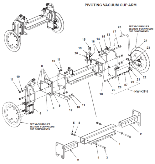
Vacuum Components & Swing Arms
Vacuum Arms (Rotary Actuator)
| ITEM | BHS PART NUMBER | DESCRIPTION | REF. KIT NO. | NOTES | NO. REQ |
|---|---|---|---|---|---|
| 1 | N/A | ARM-PUSH/PULL-30" | † Discontinued | 1 | |
| N/A | ARM-PUSH/PULL-36" | † Discontinued | 1 | ||
| 2 | HW0509 | BOLT-HHCS-1/2-13 X 4 1/2" | 3 | ||
| 3 | HW0112 | WASHER-FLAT-1/2"-SAE | 6 | ||
| 4 | HW0110 | WASHER-LOCK-1/2" | 3 | ||
| 5 | HW0007 | NUT-HEX-1/2-13 | 3 | ||
| 6 | P0505 | BUSHING-RED-#6 NPT X #4 FNPT-BRASS | 2 | ||
| 7 | P0402 | HOSE BARB-1/4 X #4 MNPT-BRASS | 2 | ||
| 8 | HW0428 | STUD-VACUUM-3/8-16 X 5" | HW-KIT-2 | 8 | |
| 9 | HW0108 | WASHER-FLAT-3/8"-SAE | HW-KIT-2 | 40 | |
| 10 | HW1001 | SPRING-3/8" | HW-KIT-2 | 24 | |
| 11 | HW0006 | NUT-NILN-3/8-16 | HW-KIT-2 | 8 | |
| 12 | HW0424 | NUT-JAM-3/8-16 | HW-KIT-2 | 8 | |
| REF | 43052006 | ADJUSTABLE PUSH/PULL ARM | Includes Items 13 through 17 | 1 | |
| 13 | 43057034 | ARM BASE | 1 | ||
| 14 | 43055008 | VACUUM CUP MOUNT | 2 | ||
| 15 | HW0523 | BOLT-HHCS-1/2-13 X 4" | 2 | ||
| 16 | HW0112 | WASHER-FLAT-1/2"-SAE | 4 | ||
| 17 | HW0008 | NUT-NILN-1/2-13 | 2 | ||
| NOTES | |||||
| † One-piece Arms no longer available. Must replace with Adjustable Arm. | |||||
Vacuum Cups
| ITEM | BHS PART NUMBER | DESCRIPTION | REF. KIT NO. | NOTES | NO. REQ |
|---|---|---|---|---|---|
| A/R | 00162004 | VACUUM CUP-10" 3-PC (STANDARD) | † Includes Items 1 through 4 | A/R | |
| 00162003 | VACUUM CUP-12" 3-PC (STANDARD) | † Includes Items 4 through 7 | |||
| 00162007 | VACUUM CUP-10" 3-PC, REINFORCED | Includes Items 1,3,4 & 8 | |||
| 00162005 | VACUUM CUP-12" 3-PC, REINFORCED | Includes Items 4,5,7 & 9 | |||
| 1 | 00164006 | CASTING-10" VACUUM CUP | 10" cup only | 1 | |
| 2 | 00164004 | SEAL-RUBBER-10" | 1 | ||
| 3 | 00165002 | PLATE-FRONT-10" | 1 | ||
| 4 | HW0311 | BOLT-FHSCS-1/4-20 X 3/4" | 8 | ||
| 5 | 00166001 | CASTING-12" VACUUM CUP | 12" cup only | 1 | |
| 6 | 00164001 | SEAL-RUBBER-12" | 1 | ||
| 7 | 00165001 | PLATE-FRONT-12" | 1 | ||
| 8 | 00164007 | SEAL-RUBBER-10"-REINFORCED | A/R | ||
| 9 | 00167003 | SEAL-RUBBER-12"-REINFORCED | A/R | ||
| NOTES | |||||
| † 10" and 12" 1-Piece Cups no longer available. Must replace with 3-Piece Cup. Verify required cup size prior to ordering. | |||||
Swing Arms (Rotary Actuator)
| ITEM | BHS PART NUMBER | DESCRIPTION | REF. KIT NO. | NOTES | NO. REQ |
| 1 | 45055001 | TIE PLATE-SWING ARM | BE-24-2-TS | 1 | |
| 45255001 | TIE PLATE-SWING ARM | BE-36-2-TS (NOT SHOWN) | 1 | ||
| 45355001 | TIE PLATE-SWING ARM | BE-42-2-TS (NOT SHOWN) | 1 | ||
| 2 | 43055004 | SWING ARM-RHS | † | NOT SOLD INDIVIDUALLY | 1 |
| 3 | 43055002 | SWING ARM-LHS | † | NOT SOLD INDIVIDUALLY | 1 |
| 4 | HW0603 | BOLT-FHSCS-5/8-11 X 2" | 4 | ||
| 5 | HW0113 | WASHER-LOCK-5/8" | 4 | ||
| 6 | HW0010 | NUT-JAM-5/8-11 | 4 | ||
| 7 | PT0413 | COLLAR-SHAFT-3" | 80252001 | 2 | |
| 8 | 43027001 | SHAFT-ROTARY ACTUATOR | 80252001 | 1 | |
| 9 | HW1013 | KEY-3/8" X 12" | 80252001 | 1 | |
| 10 | PT0419 | BEARING-SAE 841-2" I.D., 3" OD, 1/8" THICK | 80252001 | 3 | |
| 11 | 43052005 | CAP-BEARING | INCLUDES BEARING | 2 | |
| 12 | HW0303 | BOLT-HHCS-1/4-20 X 1" | 6 | ||
| 13 | HW0103 | WASHER-LOCK-1/4" | 6 | ||
| 14 | 43057014 | STANDOFF-WIRE | 1 | ||
| 15 | HW0312 | SCREW-SHSS-1/4-20 X 1"-CUP POINT | 1 | ||
| 16 | 43057003 | CUSHION-SWING ARM | 2 | ||
| 17 | HW0306 | BOLT-FHSCS-1/4-20 X 1" | 4 | ||
| 18 | 43055001 | STOP-SWING ARM | 2 | ||
| 19 | HW0403 | BOLT-HHCS-3/8-16 X 1 1/4" | 4 | ||
| 20 | HW0107 | WASHER-LOCK-3/8" | 4 | ||
| 21 | HW0108 | WASHER-FLAT-3/8"-SAE | 4 | ||
| 22 | H1565 | ADAPTER-45 DEG-#6 JICM X #4 MNPT | 2 | ||
| 23 | H1600 | ADAPTER-90 DEG-#6 JICM X #8 SAEM | 2 | ||
| NOTES | |||||
|---|---|---|---|---|---|
| † Included in multiple kits. | |||||
| See Single Compartment Swing Arm Stop for the the Single Compartment Swing Arm Stop. | |||||
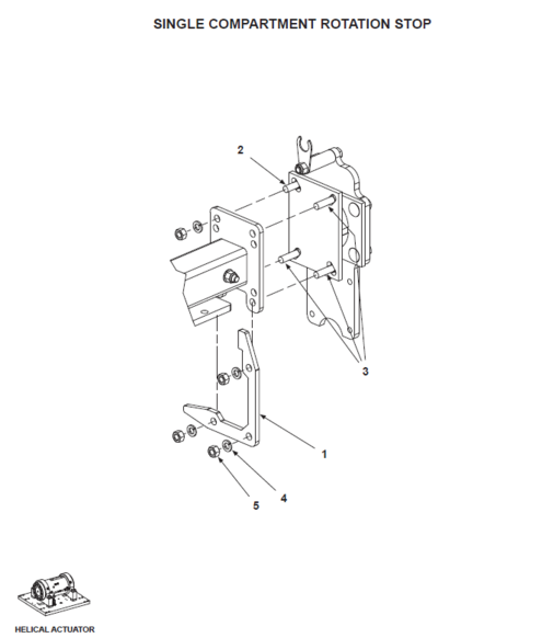
Vacuum Swing Arm Stop (Rotary Actuator)
| ITEM | BHS PART NUMBER | DESCRIPTION | REF. KIT NO. | NOTES | NO. REQ |
|---|---|---|---|---|---|
| 1 | 44555001 | STOP-SWING ARM | 1 | ||
| 2 | 43057003 | CUSHION-SWING ARM | 1 | ||
| 3 | 43057008 | SPACER-SWING ARM STOP | 1 | ||
| 4 | HW0306 | BOLT-FHSCS-1/4-20 X 1" | 2 | ||
| 5 | HW0403 | BOLT-HHCS-3/8-16 X 1 1/4" | 4 | ||
| 6 | HW0107 | WASHER-LOCK-3/8" | 4 |
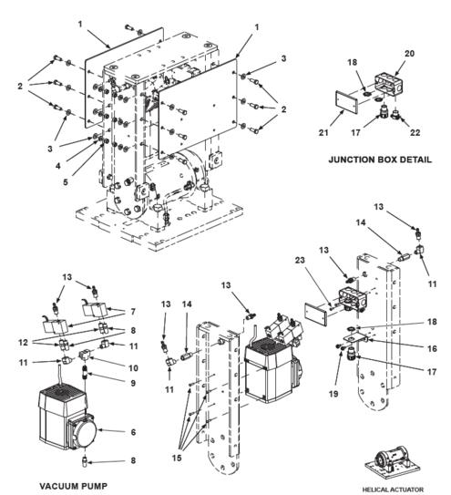
Vacuum Pump (Rotary Actuator)
| ITEM | BHS PART NUMBER | DESCRIPTION | REF. KIT NO. | NOTES | NO. REQ |
|---|---|---|---|---|---|
| 1 | P0005 | PUMP-VACUUM | 1 | ||
| 2 | P0208 | FILTER-HI FLOW | 3 | ||
| 3 | P0503 | NIPPLE-#4 NPT-BRASS | 3 | ||
| 4 | P0502 | TEE-#4 FNPT-BRASS | 1 | ||
| 5 | P0506 | ELBOW-STR-90 DEG-#4 NPT-BRASS | 4 | ||
| 6 | P0402 | HOSE BARB-1/4 X #4 NPTM-BRASS | 6 | ||
| 7 | P0207 | VALVE-VACUUM RELEASE | 2 | ||
| 8 | P0302 | HOSE-VACUUM-1/4" I.D. | Two 6" pieces | 1' | |
| 9 | P0302 | HOSE-VACUUM-1/4" I.D. | Short Arm side | 1' | |
| 10 | P0302 | HOSE-VACUUM-1/4" I.D. | Long Arm side | 2' | |
| 11 | E0611 | JUNCTION BOX-4" X 2" X 2" | 1 | ||
| 12 | E0612 | COVER-JUNCTION BOX | 1 | ||
| 13 | HW0212 | SCREW-RHMS-#10-24 X 1/2" | 2 | ||
| 14 | E0624 | CONNECTOR-1/2" | 1 | ||
| 15 | E0608-1 | RESTRAINT-1/2"-90 DEG | Grip size .450" to .560" | 1 | |
| 15a | E0617 | LOCKNUT-CONDUIT-1/2" | Not shown | 2 | |
| 16 | E0501 | CORD-14-4 SW/SOW | Withtout Ground Connection in Arm | 15' | |
| E0514 | CORD-16-5 SW/SOW | ||||
| 17 | 43057014 | STANDOFF-CABLE | 1 | ||
| 18 | HW0206 | SCREW-RHMS-#10-32 X 3/4" | 4 | ||
| 19 | HW0306 | BOLT-FHSCS-1/4-20 X 1" | 1 | ||
| 20 | 43057021 | PLATE-STIFFENER | † | 2 | |
| 21 | HW0402 | BOLT-HHCS-3/8-16 X 1" | † | 12 | |
| 22 | HW0107 | WASHER-LOCK-3/8" | † | 12 | |
| 23 | HW0005 | NUT-HEX-3/8-16 | † | 12 | |
| 24 | HW0108 | WASHER-FLAT-3/8"-SAE | † | Not shown | 24 |
| 25 | P0111 | FILTER-VACUUM-INLINE | Not shown | 2 | |
| NOTES | |||||
| † Included in multiple kits. | |||||
Rotary Actuator
| ITEM | BHS PART NUMBER | DESCRIPTION | REF. KIT NO. | NOTES | NO. REQ |
|---|---|---|---|---|---|
| 1 | 43046001 | ROTARY ACTUATOR | 1 | ||
| 2 | 80000002 | ROTARY ACTUATOR BASE ASSEMBLY | Without Actuator | 1 | |
| 2A | N/A | VERTICAL CARRIER PLATE-OUTER | Included with 80000002 | 2 | |
| 2B | N/A | VERTICAL CARRIER PLATE-INNER | Included with 80000002 | 1 | |
| 2C | N/A | CARRIER BASE PLATE | Included with 80000002 | 1 | |
| 3 | HW1070 | PIN-PULL DOWEL-5/8" X 1 1/2" | 2 | ||
| 4 | HW0508 | BOLT-SHCS-1/2-13 X 3/4" | 3 | ||
| 5 | HW1045 | PIN-PULL DOWEL-3/8" X 1 1/2" | Included with 80000002 | 6 | |
| 6 | HW0412 | BOLT-SHCS-3/8-16 X 1 1/4" | Included with 80000002 | 12 | |
| 7 | H0010 | FITTING-BULKHEAD-3/4-16 X #4 FNPT | 4 | ||
| 8 | H1579 | ADAPTER-90 DEG-#6 JICM X #4 NPTM | 2 |
Carrier Shafts & Bearings (Rotary Actuator)
| ITEM | BHS PART NUMBER | DESCRIPTION | REF. KIT NO. | NOTES | NO. REQ |
|---|---|---|---|---|---|
| 1 | 43057045 | CARRIER SHAFT-EXTRACTOR ARM | † See notes | 2 | |
| 2 | 43054007 | BEARING-EXTRACTOR ARM CARRIER | 80252002 | †† See notes | 4 |
| 3 | HW0412 | BOLT-SHCS-3/8-16 X 1 1/4" | 80252002 | 16 | |
| 4 | PT0413 | COLLAR-SHAFT-3" | 4 | ||
| 5 | PT0624 | FITTING-ZERK | 80252002 | Not shown | 4 |
| NOTES | |||||
| † See Vacuum Extended Reach (Rotary Actuator) section for Extended Reach equipped units. | |||||
| †† See Carrier Shafts & Bearings (Helical Actuator) section for Helical Actuator equipped units. | |||||
Drive Screw Components (Rotary Actuator)
Drive Nut Assembly (Rotary Actuator)
| ITEM | BHS PART NUMBER | DESCRIPTION | REF. KIT NO. | NOTES | NO. REQ |
|---|---|---|---|---|---|
| 1 | 43054006 | DRIVE NUT ASSEMBLY | 80252003 | † See notes | 1 |
| 2 | HW0426 | BOLT-SHCS-3/8-16 X 5 1/2" | 80252003 | †† See notes | 4 |
| 3 | HW0108 | WASHER-FLAT-3/8"-SAE | 80252003 | †† See notes | 4 |
| 4 | HW0006 | NUT-NILN-3/8-16 | 80252003 | †† See notes | 4 |
| 5 | PT0624 | FITTING-ZERK | 80252003 | 1 | |
| NOTES | |||||
| † See Drive Nut Assembly (Helical Actuator) section for Helical Actuator equipped units. | |||||
| †† It is recommended to replace mounting hardware when replacing Drive Nut Assembly. | |||||
Drive Screw
[Current] Drive Screw Assembly (Frame #'s 374 to Present)
| ITEM | BHS PART NUMBER | DESCRIPTION | REF. KIT NO. | NOTES | NO. REQ |
|---|---|---|---|---|---|
| 1 | 43024001 | SCREW-LINEAR DRIVE | 1 | ||
| 2 | PT0119 | SPROCKET-50B15 X 1 3/16" | 1 | ||
| 3 | 43097004 | KEY-1/4 X 7/8" | 1 | ||
| 4 | 00158001-15 | CHAIN-ROLLER-#50 | 1 | ||
| 5 | PT0102 | LINK-CONNECTING-#50 | 1 | ||
| 6 | PT0406 | FLANGE BEARING-4 BOLT-1 3/16" | Alloy casting | 2 | |
| 7 | HW0503 | BOLT-HHCS-1/2-13 X 1 1/2" | 8 | ||
| 8 | HW0110 | WASHER-LOCK-1/2" | 8 | ||
| 9 | PT0107 | SPROCKET-50B15 X 1" | 1 | ||
| 10 | HC0121 | MOTOR-HYDRAULIC-100CC | SAE 2-Bolt mount | 1 | |
| 11 | H1605 | ADAPTER-90 DEG-#6 JICM X #10 SAEM | 2 | ||
| 12 | HW1071 | KEY-WOODRUFF-#808 STD | Supplied with Item 10 | A/R | |
| 13 | HW0403 | BOLT-HHCS-3/8-16 X 1 1/4" | 6 | ||
| 14 | HW0107 | WASHER-LOCK-3/8" | 6 | ||
| 15 | 43017007 | PLATE-MOUNTING-SCREW DRIVE MOTOR | 1 | ||
| 16 | 43057019 | PLATE-COVER | 2 | ||
| 17 | HW0415 | BOLT-SHCS-3/8-16 X 3/4" | 8 |
| ITEMS BELOW ARE REQUIRED FOR REPLACING THE LINEAR DRIVE
SCREW ON UNITS WITH FRAME #'S OF 373 AND EARLIER | |||||
|---|---|---|---|---|---|
| LINEAR DRIVE SCREW UPDATE KIT | |||||
| REF | 80252011 | UPGRADE KIT | 1 | ||
| 1 | 43024001 | SCREW-LINEAR DRIVE | 1 | ||
| 2 | PT0119 | SPROCKET-50B15 X 1 3/16" | 1 | ||
| 3 | 43097004 | KEY-1/4" X 7/8" | 1 | ||
| 6 | PT0406 | FLANGE BEARING-4 BOLT-1 3/16" | Alloy casting | 2 | |
| 7 | HW0503 | BOLT-HHCS-1/2-13 X 1 1/2" | 8 | ||
| 8 | HW0110 | WASHER-LOCK-1/2" | 8 | ||
| 16 | 43057019 | PLATE-COVER | 2 | ||
| - | 43057022 | SHIM-18GA | May not be required - (Not shown) | 2 | |
| - | 43057018 | TEMPLATE-BEARING MOUNT PATTERN | (Not shown) | 1 | |
| - | 43057020 | SPACER PLATE | (Not shown) | 2 | |
| - | 80000015 | INSTRUCTION DETAIL | (Not shown) | REF | |
[Discontinued] Drive Screw Assembly (Frame #'s 373 and Earlier)
| ITEM | BHS PART NUMBER | DESCRIPTION | REF. KIT NO. | NOTES | NO. REQ |
|---|---|---|---|---|---|
| 1 | N/A | SCREW-LINEAR DRIVE (DISCONTINUED) | See 80252011 Upgrade Kit | 1 | |
| 2 | PT0118 | SPROCKET-50B12 X 1 3/16" | 1 | ||
| 3 | 43097004 | KEY-1/4" X 7/8" | 1 | ||
| 4 | 00158001-15 | CHAIN-ROLLER-#50 | 1 | ||
| 5 | PT0102 | LINK-CONNECTING-#50 | 1 | ||
| 6 | 43057016 | BLOCK-BEARING RETAINER | 2 | ||
| 6a | PT0414 | RACE-TAPERED ROLLER BEARING | Included with 43057016 | 2 | |
| 7 | PT0623 | SEAL-GREASE | 2 | ||
| 8 | HW0416 | BOLT-SHCS-3/8-16 X 1" | 8 | ||
| 9 | PT0415 | BEARING-TAPERED ROLLER | 2 | ||
| 10 | HW1050 | NUT-LOCK | 4 | ||
| 11 | 43057017 | PLATE-COVER | 2 | ||
| 12 | HW0415 | BOLT-SHCS-3/8-16 X 3/4" | 8 | ||
| 13 | PT0624 | FITTING-ZERK | 2 |
Hose Carrier Plate
| ITEM | BHS PART NUMBER | DESCRIPTION | REF. KIT NO. | NOTES | NO. REQ |
|---|---|---|---|---|---|
| 1 | 43915018 | PLATE-HOSE CARRIER | 1 | ||
| 2 | PT0618 | BRACKET-FIXED END | 1 | ||
| 3 | HW0301 | BOLT-SELF TAP "F"-1/4-20 X 1/2" | 2 | ||
| 4 | PT0617 | HOSE CARRIER | 20 links required | 3 FT | |
| 5 | PT0619 | BRACKET-MOVING END | 1 | ||
| 6 | HW0303 | BOLT-HHCS-1/4-20 X 1" | 2 | ||
| 7 | HW0103 | WASHER-LOCK-1/4" | 2 | ||
| 8 | HW0403 | BOLT-HHCS-3/8-16 X 1 1/4" | † See notes | 2 | |
| 9 | HW0108 | WASHER-FLAT-3/8"-SAE | 6 | ||
| 10 | HW0107 | WASHER-LOCK-3/8" | 4 | ||
| 11 | HW0005 | NUT-HEX-3/8-16 | 4 | ||
| 12 | HC0262 | VALVE-CROSS PORT RELIEF | Includes cartridges | 1 | |
| 12a | 43846002 | REPLACEMENT CARTRIDGE | †† For Item 12 (Not shown) | 2 | |
| 13 | HW0308 | BOLT-HHCS-1/4-20 X 2 1/2" | 2 | ||
| 14 | HW0104 | WASHER-FLAT-1/4"-SAE | 2 | ||
| 15 | HW0103 | WASHER-LOCK-1/4" | 2 | ||
| 16 | HW0002 | NUT-HEX-1/4-20 | 2 | ||
| 17 | H1560 | ADAPTER-45 DEG-#8 JICM X #8 SAEM | 4 | ||
| 18 | E1329 | JUNCTION BOX-4" X 4" X 2" | PVC - Includes cover | 1 | |
| 19 | HW0212 | SCREW-RHMS-#10-24 X 1/2" | 4 | ||
| 20 | HW0102 | WASHER-FLAT-#10-SAE | 4 | ||
| 21 | E0623 | RESTRAINT-1/2"-90 DEG | Grip size .250" to .375" | 2 | |
| 22 | E0622 | RESTRAINT-1/2" | Grip size .450" to .560" | 1 | |
| 23 | E0617 | LOCKNUT-CONDUIT-1/2" | For Items 21 & 22 (Not shown) | 3 | |
| 24 | HW1076 | BOLT-FHSCS-3/8-16 X 1" | † See notes | 2 | |
| NOTES | |||||
| † Units built prior to February 2014 without extended reach option use (4) HW0403 mounting bolts.
†† Cartridges are for replacement only. | |||||
Magnet Components (Rotary Actuator)
[Discontinued] Magnet Arm Configuration
| ITEM | BHS PART NUMBER | DESCRIPTION | REF. KIT NO. | NOTES | NO. REQ |
|---|---|---|---|---|---|
| 1 | 41257014 | TIE PLATE-SWING ARM | All units | 1 | |
| - | 41655008 | EXTENSION-ARM | BE-36 only (Not shown) | 1 | |
| - | 43455001 | EXTENSION-ARM | BE-42 only (Not shown) | 1 | |
| 2 | HW0603 | BOLT-FHSCS-5/8-11 X 2" | 4 | ||
| 3 | HW0113 | WASHER-LOCK-5/8" | 4 | ||
| 4 | HW0010 | NUT-JAM-5/8-11 | 4 | ||
| 5 | 41655001 | CARRIER TUBE-MAGNET SWING SHAFT | 1 | ||
| 6 | HW0504 | BOLT-HHCS-1/2-13 X 2" | 6 | ||
| 7 | HW0112 | WASHER-FLAT-1/2"-SAE | 6 | ||
| 8 | HW0110 | WASHER-LOCK-1/2" | 6 | ||
| 9 | HW0007 | NUT-HEX-1/2-13 | 6 | ||
| 10 | 41657006 | SHAFT-MAGNET SWING | 1 | ||
| 11 | 41698001 | KEY-3/8" X 7/16" | 2 | ||
| 12 | N/A | STOP-MAGNET SWING | † Dicontinued | 1 | |
| 13 | PT0430 | FLANGE BEARING-4 BOLT-1 1/2" | 2 | ||
| 14 | HW0513 | BOLT-HHCS-1/2-13 X 2 1/4" | 8 | ||
| 15 | HW0112 | WASHER-FLAT-1/2"-SAE | 16 | ||
| 16 | HW0110 | WASHER-LOCK-1/2" | 8 | ||
| 17 | HW0007 | NUT-HEX-1/2-13 | 8 | ||
| 18 | 41655002 | PLATE-MAGNET MOUNTING | 2 | ||
| 19 | 41257015 | BLOCK-TIGHTENER | 2-piece item | 1 | |
| 20 | 41257016 | BLOCK-FIXED | 2-piece item | 1 | |
| 21 | HW0423 | BOLT-SHCS-3/8-16 X 3 1/2" | 4 | ||
| 22 | HW0006 | NUT-NILN-3/8-16 | 4 | ||
| 23 | HW0806 | SET SCREW-3/8-16 X 2" | Replaces Swivel Head | 4 | |
| 24 | HW0424 | NUT-JAM-3/8-16 | 4 | ||
| 25 | 41657017 | INSULATOR-MAGNET MOUNT | 2 | ||
| 26 | HW0306 | BOLT-FHSCS-1/4-20 X 1" | 8 | ||
| 27 | 41657008 | PAD-MAGNET SLIDE | 2 | ||
| 28 | HW0314 | BOLT-FHSCS-1/4-20 X 1/2" | 4 | ||
| NOTES | |||||
| † Refer to [Current] Magnet Arm Configuration (Rotary Actuator) section for replacement / upgrade parts. | |||||
Magnet Pivot Stop (Rotary Actuator)
| ITEM | BHS PART NUMBER | DESCRIPTION | REF. KIT NO. | NOTES | NO. REQ |
|---|---|---|---|---|---|
| 1 | N/A | MAGNET PUSH/PULL ARM | † See notes | 1 | |
| 2 | 43055010 | MAGNET MOUNT | 2 | ||
| 3 | PT0470 | BEARING-MAGNET PIVOT | 2 | ||
| 4 | HW0525 | BOLT-CARRIAGE-1/2-13 X 1 1/2" | 12 | ||
| 5 | HW0524 | BOLT-CARRIAGE-1/2-13 X 2" | †† Stop Plate location | 4 | |
| 6 | HW0110 | WASHER-LOCK-1/2" | 16 | ||
| 7 | HW0007 | NUT-HEX-1/2-13 | 16 | ||
| 8 | 43058009 | PLATE-ROTATION STOP | 2 | ||
| 9 | 43058003 | SLEEVE-STOP | 2 | ||
| 10 | 43058010 | SUPPORT-CABLE | 2 | ||
| 11 | PL0501 | GROMMET-1/2" | 2 | ||
| 12 | HW0523 | BOLT-HHCS-1/2-13 X 4" | 2 | ||
| 13 | HW0008 | NUT-NILN-1/2-13 | 2 | ||
| 14 | 43057037 | INSULATOR-BOTTOM | 2 | ||
| 15 | HW0306 | BOLT-FHSCS-1/4-20 X 1" | 8 | ||
| 16 | 41657008 | SLIDE-MAGNET | 2 | ||
| 17 | HW0314 | BOLT-FHSCS-1/4-20 X 1/2" | 4 | ||
| 18 | 44558001 | PLATE-ROTATION STOP | †† Single compartment units only | 2 | |
| REF | 43052014 | ADJUSTABLE PUSH-PULL ARM | Includes Items 19-23 | A/R | |
| 19 | 43055018 | ARM BASE | 1 | ||
| 20 | 43055019 | MAGNET MOUNT | 2 | ||
| 21 | HW0523 | BOLT-HHCS-1/2-13 X 4" | 2 | ||
| 22 | HW0112 | WASHER-FLAT-1/2"-SAE | 4 | ||
| 23 | HW0008 | NUT-NILN-1/2-13 | 2 | ||
| NOTES | |||||
| † 1-Piece Arm no longer available. Must be replaced with Adjustable Arm. | |||||
| †† Single compartment Stop Plates require (1) additional 2" long Carriage Bolt each | |||||
[Current] Magnet Arm Configuration (Rotary Actuator)
| ITEM | BHS PART NUMBER | DESCRIPTION | REF. KIT NO. | NOTES | NO. REQ |
|---|---|---|---|---|---|
| REF | 80252012 | MAGNET SWING STOP KIT | Includes Items 1 through 6 | A/R | |
| 1 | 43057029 | PLATE-STOP | 1 | ||
| 2 | 43058003 | SLEEVE-STOP | 2 | ||
| 3 | 43057030 | SUPPORT-CABLE | 2 | ||
| 4 | PL0501 | GROMMET-1/2" | 2 | ||
| 5 | HW0509 | BOLT-HHCS-1/2-13 X 4 1/2" | 2 | ||
| 6 | HW0008 | NUT-NILN-1/2-13 | 2 | ||
| 7 | 44557003 | PLATE-STOP | † Single compartment units only | 1 | |
| NOTES | |||||
| † For units equipped with Pivot Shaft. See [Current] Magnet Arm Configuration (Rotary Actuator) for units with Independent Magnet Pivot Bearings. | |||||
Magnet Mounting Hardware (Rotary Actuator)
| ITEM | BHS PART NUMBER | DESCRIPTION | REF. KIT NO. | NOTES | NO. REQ |
|---|---|---|---|---|---|
| REF | 43032009 | MAGNET ASSEMBLY | Includes Items 1 through 12 | A/R | |
| 1 | N/A | ELECTROMAGNET-95VDC | 2 | ||
| 2 | E0314 | SENSOR-PROXIMITY-30MM | 2 | ||
| 3 | N/A | GASKET-REAR | Discontinued - Not used | 2 | |
| 4 | 41657002 | COVER-PROXIMITY SENSOR HOUSING | Rear | 2 | |
| 5 | HW1065 | SCREW-SHCS-#6-32 X 3/8" | 8 | ||
| 6 | HW1066 | WASHER-LOCK-#6 | 8 | ||
| 7 | E0376 | INDICATOR LIGHT | † See notes | 2 | |
| 8 | E0335 | RECEPTACLE-5 PIN MALE | With 12" lead | 2 | |
| 9 | E0617 | LOCKNUT-CONDUIT-1/2" | 2 | ||
| 10 | N/A | GASKET-FRONT | Discontinued - Not used | 2 | |
| 11 | 41657003 | COVER-PROXIMITY SENSOR HOUSING | 80252015 | Front | 2 |
| 12 | HW0138 | SCREW-FHSCS-#8-32 X 3/8" | 80252015 | 8 | |
| 13 | HW0433 | STUD-1/2-13 X 5" | 80252006 | For units with Magnet Pivot Shaft only.
See [Discontinued] Magnet Arm Configuration for units built prior to 11/01/14 |
8 |
| 14 | HW0007 | NUT-HEX-1/2-13 | 80252006 | 8 | |
| 15 | HW0112 | WASHER-FLAT-1/2"-SAE | 80252006 | 40 | |
| 16 | HW1002 | SPRING-1/2" | 80252006 | 24 | |
| 17 | HW0008 | NUT-NILN-1/2-13 | 80252006 | 8 | |
| 18 | HW0514 | BOLT-HHCS-1/2-13 X 2 1/2" | 80252014 | For units with independent Pivot Bearings only.
See [Current] Magnet Arm Configuration for units built 11/01/14 to present) |
4 |
| 19 | HW1002 | SPRING-1/2" | 80252014 | 4 | |
| 20 | HW0112 | WASHER-FLAT-1/2"-SAE | 80252014 | 8 | |
| 21 | HW0007 | NUT-HEX-1/2-13 | 80252014 | 4 | |
| NOTES | |||||
| † Extractors built or replacement magnets shipped prior to October 2021 used multi-piece indicator lights with replaceable bulb and lens and are no longer available. Current indicator light is a 1-piece LED assembly. Replacement of any multi-piece component requires replacing entire assembly with current, 1-piece indicator light. | |||||
Magnet Cords (Rotary Actuator)
| ITEM | BHS PART NUMBER | DESCRIPTION | REF. KIT NO. | NOTES | NO. REQ |
|---|---|---|---|---|---|
| 1 | E1105 | JUNCTION BOX-4" X 2" X 2" | Weather proof box | 1 | |
| 2 | HW0301 | BOLT-SELF TAP "F"-1/4-20 X 1/2" | 2 | ||
| 3 | E1106 | COVER-JUNCTION BOX | Weather proof with gasket | 1 | |
| 4 | E0333 | RECEPTACLE-9 PIN MALE | With 12" lead | 1 | |
| 5 | E0608-1 | RESTRAINT-1/2"-90 DEG | Grip size .450" to .560" | 2 | |
| 6 | E0617 | LOCKNUT-CONDUIT-1/2" | 3 | ||
| 7 | E0334 | CORD-5 PIN FEMALE | With 36" lead | 2 | |
| 8 | E0332 | CORD-9 PIN FEMALE-90 DEG | With 36" lead | 1 | |
| 9 | PL0501 | GROMMET-1/2" | 1 | ||
| 10 | 41657013-2 | PLATE-PANEL MOUNTING | With single cable hole | 1 | |
| 11 | E0334-6 | CORD-5 PIN FEMALE | With 72" lead | 2 | |
| 12 | 43057038-2 | PLATE-PANEL MOUNTING | With dual cable holes | 1 |
Magnet Panel Mounting (Rotary Actuator)
| ITEM | BHS PART NUMBER | DESCRIPTION | REF. KIT NO. | NOTES | NO. REQ |
|---|---|---|---|---|---|
| 1 | 43057021 | PLATE-STIFFENER | 1 | ||
| 2 | HW0402 | BOLT-HHCS-3/8-16 X 1" | 12 | ||
| 3 | HW0108 | WASHER-FLAT-3/8"-SAE | Not shown | 24 | |
| 4 | HW0107 | WASHER-LOCK-3/8" | 12 | ||
| 5 | HW0005 | NUT-HEX-3/8-16 | 12 | ||
| 6 | 41637001 | PANEL-COMPONENT MOUNTING | 1 | ||
| 7 | HW0325 | BOLT-5/16-18 X 1 3/4"-PAN HEAD | 4 | ||
| 8 | N/A | INSULATOR-THREADED FEMALE | Discontinued | 4 | |
| 9 | HW0106 | WASHER-FLAT-5/16"-SAE | 8 | ||
| 10 | HW0326 | NUT-NILN-5/16-18 | 8 | ||
| 11 | E1016 | FUSE HOLDER | 1 | ||
| 12 | HW0130 | SCREW-RHMS-#8-32 X 1/2" | 1 | ||
| 13 | HW0133 | WASHER-FLAT-#8-SAE | 1 | ||
| 14 | HW0132 | NUT-NILN-#8-32 | 1 | ||
| 15 | E0325 | FUSE-7AMP-250VAC | FLM-7 or FNM-7 | 1 | |
| 16 | PL0307 | INSULATOR-MALE STUD | 4 |
Magnet Extractor Electrical Panel (Rotary Actuator)
| ITEM | BHS PART NUMBER | DESCRIPTION | REF. KIT NO. | NOTES | NO. REQ |
|---|---|---|---|---|---|
| 1 | 41637001 | PANEL-COMPONENT MOUNTING | 1 | ||
| 2 | 41637002 | WIRE WAY | 2 | ||
| 3 | 41637003 | WIRE WAY | 1 | ||
| 4 | 41637004 | TRACK-TERMINAL BLOCK MOUNTING | 1 | ||
| 5 | 41637005 | TRACK-TERMINAL BLOCK MOUNTING | 1 | ||
| 6 | HW0130 | SCREW-RHMS-#8-32 X 1/2" | 10 | ||
| 7 | HW0132 | WASHER-FLAT-#8-SAE | 10 | ||
| 8 | HW0133 | NUT-NILN-#8-32 | Not shown | 16 | |
| 9 | E1020 | TERMINAL BLOCK | 12 | ||
| 10 | E1040 | END BARRIER | 2 | ||
| 11 | E1330 | END ANCHOR | 4 | ||
| 12 | E1009 | RECTIFIER-FULL WAVE BRIDGE | 2 | ||
| 13 | HW0135 | SCREW-RHMS-#8-32 X 3/4" | 2 | ||
| 14 | E1313 | SOCKET-RELAY-8 PIN | 2 | ||
| 15 | HW0139 | SCREW-RHMS-#8-32 X 1 1/4" | 4 | ||
| 16 | E0331 | RELAY-DPDT-110VAC | with Indicator Light | 2 |
Swing Arm Stop (Rotary Actuator)
| ITEM | BHS PART NUMBER | DESCRIPTION | REF. KIT NO. | NOTES | NO. REQ |
|---|---|---|---|---|---|
| 1 | 43055007 | MOUNT-STOP-SWING ARM | † See notes | 2 | |
| 2 | 43057024 | STOP-SWING ARM | BE-24 | 4 | |
| 43057023 | STOP-SWING ARM | BE-36 & BE-42 | 4 | ||
| 3 | HW0304 | BOLT-HHCS-1/4-20 X 1 1/2" | 4 | ||
| 4 | HW0104 | WASHER-FLAT-1/4"-SAE | 8 | ||
| 5 | HW0103 | WASHER-LOCK-1/4" | 4 | ||
| 6 | HW0002 | NUT-HEX-1/4-20 | 4 | ||
| 7 | HW0403 | BOLT-HHCS-3/8-16 X 1 1/4" | 4 | ||
| 8 | HW0107 | WASHER-LOCK-3/8" | 4 | ||
| 9 | HW0108 | WASHER-FLAT-3/8"-SAE | 4 | ||
| NOTES | |||||
| † See Vacuum Swing Arm Stop (Rotary Actuator) section for single compartment stop mount and stop. | |||||
Vacuum Extended Reach (Rotary Actuator)
| ITEM | BHS PART NUMBER | DESCRIPTION | REF. KIT NO. | NOTES | NO. REQ |
|---|---|---|---|---|---|
| 1 | 41257014 | TIE PLATE-SWING ARM | All units | 1 | |
| - | 41655008 | EXTENSION-ARM | BE-36 only (Not shown) | 1 | |
| - | 43455001 | EXTENSION-ARM | BE-42 only (Not shown) | 1 | |
| 2 | HW0504 | BOLT-HHCS-1/2-13 X 2" | 6 | ||
| 3 | HW0112 | WASHER-FLAT-1/2"-SAE | 6 | ||
| 4 | HW0110 | WASHER-LOCK-1/2" | 6 | ||
| 5 | HW0007 | NUT-HEX-1/2-13 | 6 | ||
| 6 | P0301-1 | HOSE-COIL-VACUUM | 1 | ||
| 7 | 41257035 | STANDOFF | 2 | ||
| 8 | HW1072 | RESTRAINT-HOSE | 2 | ||
| 9 | HW0104 | WASHER-FLAT-1/4"-SAE | 2 | ||
| 10 | HW0103 | WASHER-LOCK-1/4" | 2 | ||
| 11 | HW0318 | BOLT-SHCS-1/4-20 X 1 1/2" | 2 | ||
| 12 | HW0302 | BOLT-HHCS-1/4-20 X 3/4" | 1 | ||
| 13 | HW0312 | SCREW-SHSS-1/4-20 X 1"-CUP POINT | 1 |
| ITEM | BHS PART NUMBER | DESCRIPTION | REF. KIT NO. | NOTES | NO. REQ |
|---|---|---|---|---|---|
| 1 | 41255005 | ARM-EXTENSION-VACUUM | 1 | ||
| 2 | HC0416 | CYLINDER-EXTENDED REACH-VACUUM | 2 1/2" X 12" Cylinder | 1 | |
| 3 | H1578 | ADAPTER-90 DEG-#6 JICM X #6 MNPT | 2 | ||
| 4 | 41257031 | PIN-CLEVIS END | 1 | ||
| 5 | 00197036 | PIN-ROD END | 1 | ||
| 6 | HW1058 | PIN-HITCH | 4 |
| ITEM | BHS PART NUMBER | DESCRIPTION | REF. KIT NO. | NOTES | NO. REQ |
|---|---|---|---|---|---|
| 1 | 41255004 | HOUSING-EXTENDED REACH-VACUUM | 1 | ||
| 2 | 41257030 | PLATE-END | 1 | ||
| 3 | HW0402 | BOLT-HHCS-3/8-16 X 1" | 4 | ||
| 4 | HW0108 | WASHER-FLAT-3/8"-SAE | 8 | ||
| 5 | HW0107 | WASHER-LOCK-3/8" | 4 | ||
| 6 | HW0005 | NUT-HEX-3/8-16 | 4 | ||
| 7 | 41258002 | PLATE-BEARING | 80258001 | Side | 2 |
| 8 | 41258005 | PLATE-SHIM | 80258001 | Side | 2 |
| 9 | 41258003 | PLATE-BEARING | 80258001 | Upper / lower | 2 |
| 10 | 41258004 | PLATE-SHIM | 80258001 | Upper / lower | 2 |
| 11 | HW0812 | SCREW-SHSS-1/4-20 X 5/8"-HALF DOG | 28 | ||
| 12 | HW0002 | NUT-HEX-1/4-20 | 28 |
Extended Reach (Rotary Actuator)
| ITEM | BHS PART NUMBER | DESCRIPTION | REF. KIT NO. | NOTES | NO. REQ |
|---|---|---|---|---|---|
| 1 | 43046001 | ROTARY ACTUATOR | 1 | ||
| 2 | 80000002 | ROTARY ACTUATOR BASE ASSEMBLY | Without Actuator | 1 | |
| 2A | N/A | VERTICAL CARRIER PLATE-OUTER | Included with 80000002 | 2 | |
| 2B | N/A | VERTICAL CARRIER PLATE-INNER | Included with 80000002 | 1 | |
| 2C | N/A | CARRIER BASE PLATE | Included with 80000002 | 1 | |
| 3 | HW1070 | PIN-PULL DOWEL-5/8" X 1 1/2" | 2 | ||
| 4 | HW0508 | BOLT-SHCS-1/2-13 X 3/4" | 3 | ||
| 5 | HW1045 | PIN-PULL DOWEL-3/8" X 1 1/2" | Included with 80000002 | 6 | |
| 6 | HW0412 | BOLT-SHCS-3/8-16 X 1 1/4" | Included with 80000002 | 12 | |
| 7 | H0010 | FITTING-BULKHEAD-3/4-16 X #4 FNPT | 4 | ||
| 8 | H1579 | ADAPTER-90 DEG-#6 JICM X #4 MNPT | 4 |
| ITEM | BHS PART NUMBER | DESCRIPTION | REF. KIT NO. | NOTES | NO. REQ |
|---|---|---|---|---|---|
| 1 | PT0634 | BRACKET-MALE END | Sols as a set | 1 | |
| 2 | HW0306 | BOLT-FHSCS-1/4-20 X 1" | 4 | ||
| 3 | HW0104 | WASHER-FLAT-1/4"-SAE | 10 | ||
| 4 | HW0103 | WASHER-LOCK-1/4" | 6 | ||
| 5 | HW0002 | NUT-HEX-1/4-20 | 6 | ||
| 6 | PT0627 | HOSE CARRIER | 14 links required | 39" | |
| 7 | PT0634 | BRACKET-FEMALE END | Sols as a set | 1 | |
| 8 | HC0262 | VALVE-CROSS PORT RELIEF | 1 | ||
| 8a | 43046003 | REPLACEMENT CARTRIDGE | † For Item 8 (Not shown) | 2 | |
| 9 | HW0308 | BOLT-HHCS-1/4-20 X 2 1/2" | 2 | ||
| 10 | H1546 | ADAPTER-#6 JICM X #8 SAEM | 2 | ||
| 11 | H1617 | ADAPTER-45 DEG-#6 JICM X #8 SAEM | 2 | ||
| 12 | HC0237 | VALVE-SEQUENCING | 1 | ||
| 12a | 43046005 | REPLACEMENT CARTRIDGE | † For Item 12 (Not shown) | A/R | |
| 13 | HW0317 | BOLT-HHCS-1/4-20 X 3 1/2" | 2 | ||
| 14 | H1560 | ADAPTER-45 DEG-#8 JICM X #8 SAEM | 4 | ||
| 15 | H1600 | ADAPTER-90 DEG-#6 JICM X #8 SAEM | 2 | ||
| NOTES | |||||
| † Cartridges are for replacement only | |||||
Magnet Extended Reach (Rotary Actuator)
| ITEM | BHS PART NUMBER | DESCRIPTION | REF. KIT NO. | NOTES | NO. REQ |
|---|---|---|---|---|---|
| 1 | 43055011 | ARM-EXTENSION-MAGNET | 1 | ||
| 2 | HC0415 | CYLINDER-EXTENDED REACH-MAGNET | 2 1/2" X 8" Cylinder | 1 | |
| 3 | H1578 | ADAPTER-90 DEG-#6 JICM X #6 MNPT | 2 | ||
| 4 | 43057042 | PIN-CLEVIS END | 1 | ||
| 5 | 43057043 | PIN-ROD END | 1 | ||
| 6 | HW1132 | RETAINING RING-EXTERNAL-3/4" I.D. | 4 | ||
| 7 | HW1043 | CLAMP-CYLINDER | 2 | ||
| 8 | 43057044-2 | SUPPORT-CABLE | 2 | ||
| 9 | PL0501 | GROMMET-1/2" I.D. | 4 | ||
| 10 | 43058019 | SUPPORT-CABLE-BAND CLAMP | 2 | ||
| 11 | HW0104 | WASHER-FLAT-1/4"-SAE | 4 | ||
| 12 | HW0103 | WASHER-LOCK-1/4" | 2 |
| ITEM | BHS PART NUMBER | DESCRIPTION | REF. KIT NO. | NOTES | NO. REQ |
|---|---|---|---|---|---|
| 1 | 43055012 | HOUSING-EXTENDED REACH-MAGNET | 1 | ||
| 2 | 50057008 | PLATE-END | 1 | ||
| 3 | HW0402 | BOLT-HHCS-3/8-16 X 1" | 4 | ||
| 4 | HW0108 | WASHER-FLAT-3/8"-SAE | 8 | ||
| 5 | HW0107 | WASHER-LOCK-3/8" | 4 | ||
| 6 | HW0005 | NUT-HEX-3/8-16 | 4 | ||
| 7 | 43058013 | PLATE-BEARING-SIDE | 2 | ||
| 8 | 43058016 | PLATE-SHIM-SIDE | 2 | ||
| 9 | 43058014 | PLATE-BEARING-UPPER/LOWER | 2 | ||
| 10 | 43058015 | PLATE-SHIM-UPPER/LOWER | 2 | ||
| 11 | HW0812 | SCREW-SHSS-1/4-20 X 5/8"-HALF DOG | 24 | ||
| 12 | HW0002 | NUT-HEX-1/4-20 | 24 |
Extended Reach End Plate
| ITEM | BHS PART NUMBER | DESCRIPTION | REF. KIT NO. | NOTES | NO. REQ |
|---|---|---|---|---|---|
| 1 | N/A | CARRIER SHAFT-EXTRACTOR ARM | † 3-Hole version | A/R | |
| 2 | PT0413 | COLLAR-SHAFT-3" | 4 | ||
| 3 | 50057009 | PLATE-END-3 HOLE | Replacement part only | 4 | |
| 4 | 50057010 | SHIM-END PLATE | †† See notes | A/R | |
| 5 | HW1076 | BOLT-FHSCS-3/8-16 X 1" | 12 | ||
| 6 | 43057045 | CARRIER SHAFT-EXTRACTOR ARM | 1-Hole version | 2 | |
| 7 | 43017076 | PLATE-END-1 HOLE | 4 | ||
| 8 | HW0603 | BOLT-FHSCS-5/8-11 X 2" | 4 | ||
| NOTES | |||||
| † 3-Hole Carrier Shaft no longer available. Must replace 3-Hole shaft with current, 1-Hole version along with new ennd plates & hardware. | |||||
| †† Shim quantity varies due to manufacturing tolerances. | |||||
Carrier Shafts & Bearings
| ITEM | BHS PART NUMBER | DESCRIPTION | REF. KIT NO. | NOTES | NO. REQ |
|---|---|---|---|---|---|
| 1 | 43057045 | CARRIER SHAFT-EXTRACTOR ARM | † See notes | 2 | |
| 2 | 43054007 | BEARING-EXTRACTOR ARM CARRIER | 80252002 | 4 | |
| 3 | HW0412 | BOLT-SHCS-3/8-16 X 1 1/4" | 80252002 | 16 | |
| 4 | PT0413 | COLLAR-SHAFT-3" | 4 | ||
| 5 | 50057010 | SHIM-END PLATE | A/R | ||
| 6 | 43017076 | PLATE-END-1 HOLE | 4 | ||
| 7 | HW0603 | BOLT-FHSCS-5/8-11 X 2" | 4 | ||
| 8 | PT0624 | FITTING-ZERK | 80252002 | Not shown | 4 |
| NOTES | |||||
| † See Extended Reach End Plate section for Extended Reach equipped units. | |||||
Drive Nut Assembly (Helical Actuator)
| ITEM | BHS PART NUMBER | DESCRIPTION | REF. KIT NO. | NOTES | NO. REQ |
|---|---|---|---|---|---|
| 1 | 43054006 | DRIVE NUT ASSEMBLY | 80252003 | 1 | |
| 2 | HW0426 | BOLT-SHCS-3/8-16 X 5 1/2" | 80252003 | † See notes | 4 |
| 3 | HW0108 | WASHER-FLAT-3/8"-SAE | 80252003 | † See notes | 4 |
| 4 | HW0006 | NUT-NILN-3/8-16 | 80252003 | † See notes | 4 |
| 5 | PT0624 | FITTING-ZERK | 80252003 | 1 | |
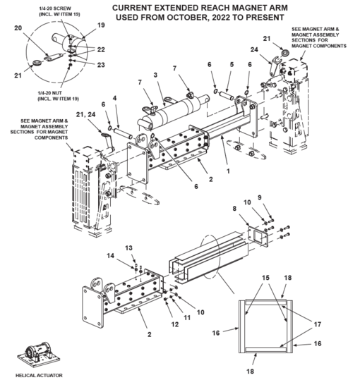
| NOTES | |||||
| † It is recommended to replce mounting hardware when replacing Drive Nut Assembly. | |||||
Swing Arms & Actuator (Helical Actuator)
[Discontinued] Helical Actuator
| ITEM | BHS PART NUMBER | DESCRIPTION | REF. KIT NO. | NOTES | NO. REQ |
|---|---|---|---|---|---|
| 1 | N/A | HELICAL ACTUATOR | † See notes | 1 | |
| 2 | 43057046 | ACTUATOR BASE PLATE | 1 | ||
| 3 | 43058022 | SPACER-ACTUATOR | 4 | ||
| 4 | HW0725 | BOLT-HHCS-3/4-16 X 4-3/4"-GR8 | 4 | ||
| 5 | HW0066 | NUT-JAM-3/4-16-GR8 | 4 | ||
| 6 | 43055013 | SWING ARM-LHS | †† See notes | 1 | |
| 7 | HW0620 | BOLT-HHCS-5/8-11 X 1-1/4" | 6 | ||
| 8 | HW0013 | WASHER-LOCK-5/8" | 6 | ||
| 9 | 43055014 | SWING ARM-RHS | 1 | ||
| 10 | HW0502 | BOLT-HHCS-1/2-13 X 1-1/4" | 6 | ||
| 11 | HW0110 | WASHER-LOCK-1/2" | 6 | ||
| 12 | 43042008 | 3/8" TUBE X #6 JIC HARD-PIPE | 1 | ||
| 13 | 43042010 | 3/8" TUBE X #6 JIC HARD-PIPE, LONG | 1 | ||
| 14 | H1619 | ADAPTER-90 DEG-#6 JICM X #4 SAEM | 2 | ||
| 15 | H0010 | FITTING-H-BULKHEAD-1/4 FNPT | 2 | ||
| 16 | H1504 | ADAPTER-#6 JICM X #4 NPTM | 2 | ||
| 17 | HW1082 | CLAMP-HOSE | 1 | ||
| 18 | HW0301 | BOLT-SELF TAP "F"-1/4-20 X 1/2" | 2 | ||
| NOTES | |||||
| † Discontinued Helical Actuator no longer available. Must replace with current Helical Actuator Retro Kit 80252032. See [Current] Helical Actuator.
†† Swing arms manufactured prior to January 2022 use 10 bolts & washers per Swing Arm. | |||||
[Current] Helical Actuator
| ITEM | BHS PART NUMBER | DESCRIPTION | REF. KIT NO. | NOTES | NO. REQ |
|---|---|---|---|---|---|
| N/A | 43052020 | HELICAL ACTUATOR ASSEMBLY | Includes Items 1 through 17 | 1 | |
| 1 | HC0180 | HELICAL ACTUATOR | 80252032 | 1 | |
| 2 | 43057046 | ACTUATOR BASE PLATE | 1 | ||
| 3 | 43058022 | SPACER-ACTUATOR | 4 | ||
| 4 | HW0725 | BOLT-HHCS-3/4-16 X 4-3/4"-GR8 | 4 | ||
| 5 | HW0066 | NUT-JAM-3/4-16-GR8 | 4 | ||
| 6 | 43055013 | SWING ARM-LHS | 1 | ||
| 7 | HW0620 | BOLT-HHCS-5/8-11 X 1-1/4" | 6 | ||
| 8 | HW0013 | WASHER-LOCK-5/8" | 6 | ||
| 9 | 43055014 | SWING ARM-RHS | 1 | ||
| 10 | HW0502 | BOLT-HHCS-1/2-13 X 1-1/4" | 6 | ||
| 11 | HW0110 | WASHER-LOCK-1/2" | 6 | ||
| 12 | 43042011 | 3/8" TUBE X #6 JIC HARD-PIPE, 90 DEG | 80252032 | † See notes | 1 |
| 13 | 43042012 | 3/8" TUBE X #6 JIC HARD-PIPE, SHORT | 80252032 | † See notes | 1 |
| 14 | H1619 | ADAPTER-90 DEG-#6 JICM X #4 SAEM | 80252032 | 2 | |
| 15 | H0010 | FITTING-H-BULKHEAD-1/4 FNPT | 2 | ||
| 16 | H1504 | ADAPTER-#6 JICM X #4 NPTM | 80252032 | 1 | |
| 17 | H1691 | ADAPTER-45 DEG-#6 JICM X #4 NPTM | 80252032 | † See notes | 1 |
| 18 | HW1082 | CLAMP-HOSE | 1 | ||
| 19 | HW0301 | BOLT-SELF TAP "F"-1/4-20 X 1/2" | 2 | ||
| NOTES | |||||
| † Hard-Pipes and 45 degree adapter required if replacing discontinued actuator with current Actuator Kit Part # 80252032 required for discontinued actuator replacement. | |||||
Swing Arm Stops & Tie Plate
| ITEM | BHS PART NUMBER | DESCRIPTION | REF. KIT NO. | NOTES | NO. REQ |
|---|---|---|---|---|---|
| 1 | 43057050 | TIE PLATE-HELICAL SWING ARM | 1 | ||
| 2 | HW0603 | BOLT-FHSCS-5/8-11 X 2" | 4 | ||
| 3 | HW0113 | WASHER-LOCK-5/8" | 4 | ||
| 4 | HW0010 | NUT-JAM-5/8-11 | 4 | ||
| 5 | 43057052 | STOP-POLY-SWING ARM | † See notes | 4 | |
| 6 | HW0441 | BOLT-FHSCS-3/8-16 X 1-1/2" | 4 | ||
| 7 | HW0031 | NUT-LOCK-3/8-16, DEFORMED THREAD | † † See notes | 4 | |
| 8 | 44555002 | SWING ARM STOP | Single compartment use only | A/R | |
| NOTES | |||||
| † Replacement Poly Stop design updated from Square to Round. Stop Spacers not required with current, Round-Style Stops. | |||||
| † † Deformed Thread Lock Nut replaces Acorn Nut and Split Lock Washer used previously. | |||||
Push/Pull Arm Mounting (Helical Actuator)
| ITEM | BHS PART NUMBER | DESCRIPTION | REF. KIT NO. | NOTES | NO. REQ | ||
|---|---|---|---|---|---|---|---|
| BE-24 | BE-36 | BE-42 | |||||
| 1 | 41655008 | EXTENSION-ARM | †BE-36 units only | - | 1 | - | |
| 43455001 | EXTENSION-ARM | †BE-42 units only | - | - | 1 | ||
| 2 | HW0504 | BOLT-HHCS-1/2-13 X 2" | 6 | 12 | |||
| 3 | HW0112 | WASHER-FLAT-1/2"-SAE | 12 | 24 | |||
| 4 | HW0110 | WASHER-LOCK-1/2" | 6 | 12 | |||
| 5 | HW0007 | NUT-HEX-1/2-13 | 6 | 12 | |||
| NOTES | |||||||
| † BE-24 units do not utilize an Arm Extension. | |||||||
Vacuum Extractor Arm (Helical Actuator)
Non-Pivoting Vacuum Cup Arm (Helical Actuator)
| ITEM | BHS PART NUMBER | DESCRIPTION | REF. KIT NO. | NOTES | NO. REQ |
|---|---|---|---|---|---|
| 1 | HW0428 | STUD-VACUUM-3/8-16 X 5" | HW-KIT-2 | 8 | |
| 2 | HW0108 | WASHER-FLAT-3/8"-SAE | HW-KIT-2 | 40 | |
| 3 | HW1001 | SPRING-3/8" | HW-KIT-2 | 24 | |
| 4 | HW0006 | NUT-NILN-3/8-16 | HW-KIT-2 | 8 | |
| 5 | HW0424 | NUT-JAM-3/8-16 | HW-KIT-2 | 8 | |
| 6 | P0402 | HOSE BARB-1/4" X #4 MNPT-BRASS | 2 | ||
| REF | 43052014 | ADJUSTABLE PUSH-PULL ARM | Includes Items 7 through 11 | A/R | |
| 7 | 43055018 | ARM BASE | 1 | ||
| 8 | 43055019 | VACUUM CUP MOUNT | 2 | ||
| 9 | HW0523 | BOLT-HHCS-1/2-13 X 4" | 2 | ||
| 10 | HW0112 | WASHER-FLAT-1/2"-SAE | 4 | ||
| 11 | HW0008 | NUT-NILN-1/2-13 | 2 |
Pivoting Vacuum Cup Arm (Helical Actuator)
| ITEM | BHS PART NUMBER | DESCRIPTION | REF. KIT NO. | NOTES | NO. REQ |
|---|---|---|---|---|---|
| REF | 43052014 | ADJUSTABLE PUSH-PULL ARM | Includes Items 1 through 5 | A/R | |
| 1 | 43055018 | ARM BASE | 1 | ||
| 2 | 43055019 | VACUUM CUP MOUNT | 2 | ||
| 3 | HW0523 | BOLT-HHCS-1/2-13 X 4" | 2 | ||
| 4 | HW0112 | WASHER-FLAT-1/2"-SAE | 4 | ||
| 5 | HW0008 | NUT-NILN-1/2-13 | 2 | ||
| 6 | 43055020 | MOUNT-PIVOT-VACUUM CUP | 2 | ||
| 7 | PT0470 | BEARING-PIVOT | 2 | ||
| 8 | HW0525 | BOLT-CARRIAGE-1/2-13 X 1 1/2" | 12 | ||
| 9 | HW0524 | BOLT-CARRIAGE-1/2-13 X 2" | 4 | ||
| 10 | HW0110 | WASHER-LOCK-1/2" | 16 | ||
| 11 | HW0008 | NUT-HEX-1/2-13 | 16 | ||
| 12 | 43058009 | PLATE-ROTATION STOP | 2 | ||
| 13 | 43058003 | SLEEVE-STOP | 2 | ||
| 14 | 43058010 | SUPPORT-CABLE | 2 | ||
| 15 | E0622 | RESTRAINT-1/2" | Grip size .450" to .560" | 4 | |
| 16 | E0617 | LOCKNUT-CONDUIT-1/2" | 4 | ||
| 17 | HW0523 | BOLT-HHCS-1/2-13 X 4" | 2 | ||
| 18 | HW0008 | NUT-NILN-1/2-13 | 2 | ||
| 19 | 43037002-2 | SUPPORT-CABLE RESTRAINT | 2 | ||
| 20 | HW0301 | BOLT-SELF TAP "F"-1/4-20 X 1/2" | 4 | ||
| 21 | P0506 | ELBOW-STR-90 DEG-#4 NPT-BRASS | 2 | ||
| 22 | P0402 | HOSE BARB-1/4" X #4 MNPT-BRASS | 2 | ||
| 23 | 43057056-2 | BRACKET-HOSE SUPPORT | 2 | ||
| 24 | PL0507 | GROMMET-5/8" I.D. | 2 | ||
| 25 | P0302 | HOSE-VACUUM-1/4" I.D. | 2 pieces at 48" each | 96" | |
| 26 | HW0443 | BOLT-HHCS-3/8-16 X 3-1/2" | HW-KIT-3 | 8 | |
| 27 | HW1001 | SPRING-3/8" | HW-KIT-3 | 16 | |
| 28 | HW0108 | WASHER-FLAT-3/8"-SAE | HW-KIT-3 | 32 | |
| 29 | HW0424 | NUT-JAM-3/8-16 | HW-KIT-3 | 4 |
Vacuum Cup Rotation Stop (Helical Actuator)
| ITEM | BHS PART NUMBER | DESCRIPTION | REF. KIT NO. | NOTES | NO. REQ |
|---|---|---|---|---|---|
| 1 | 445558001 | PLATE-ROTATION STOP | † Single compartment units only | 2 | |
| 2 | HW0525 | BOLT-CARRIAGE-1/2-13 X 1 1/2" | 2 | ||
| 3 | HW0524 | BOLT-CARRIAGE-1/2-13 X 2" | 6 | ||
| 4 | HW0110 | WASHER-LOCK-1/2" | 8 | ||
| 5 | HW0008 | NUT-HEX-1/2-13 | 8 |
Vacuum Components (Helical Actuator)
| ITEM | BHS PART NUMBER | DESCRIPTION | REF. KIT NO. | NOTES | NO. REQ |
|---|---|---|---|---|---|
| 1 | 43058021 | STIFFENER PLATE-HELICAL SWING ARM | 2 | ||
| 2 | HW0402 | BOLT-HHCS-3/8-16 X 1" | 12 | ||
| 3 | HW0108 | WASHER-FLAT-3/8" | 24 | ||
| 4 | HW0107 | WASHER-LOCK-3/8" | 12 | ||
| 5 | HW0005 | NUT-HEX-3/8-16 | 12 | ||
| 6 | P0005 | PUMP-VACUUM | 1 | ||
| 7 | P0207 | VALVE-VACUUM RELEASE | 2 | ||
| 8 | P0208 | FILTER-HI FLOW | 3 | ||
| 9 | H0011 | NIPPLE-#4 X 2"-BRASS | 1 | ||
| 10 | P0502 | TEE-#4 FNPT-BRASS | 1 | ||
| 11 | P0506 | ELBOW-STR-90 DEG-#4 NPT-BRASS | 4 | ||
| 12 | P0503 | NIPPLE-#4 NPT-BRASS | 2 | ||
| 13 | P0402 | HOSE BARB-1/4" X #4 MNPT-BRASS | 6 | ||
| 14 | P0111 | FILTER-VACUUM-IN-LINE | 2 | ||
| 15 | HW0206 | SCREW-RHMS-#10-32 X 3/4" | 4 | ||
| 16 | 43037014-2 | BRACKET-CABLE RESTRAINT | 1 | ||
| 17 | E0622 | RESTRAINT-1/2" | Grip size .450" to .560" | 2 | |
| 18 | E0617 | LOCKNUT-CONDUIT-1/2" | 2 | ||
| 19 | HW0301 | BOLT-SELF TAP "F"-1/4-20 X 1/2" | 2 | ||
| 20 | E0611 | JUNCTION BOX-4" X 2" X 2" | 1 | ||
| 21 | E0612 | COVER-JUNCTION BOX | 1 | ||
| 22 | E0624 | CONNECTOR-1/2" | Includes Lock Nut | 1 | |
| 23 | HW0212 | SCREW-RHMS-#10-24 X 1/2" | 2 |
Magnet Arm (Helical Actuator)
| ITEM | BHS PART NUMBER | DESCRIPTION | REF. KIT NO. | NOTES | NO. REQ |
|---|---|---|---|---|---|
| REF | 43052014 | ADJUSTABLE PUSH-PULL ARM | Includes Items 1 through 5 | A/R | |
| 1 | 43055018 | ARM BASE | 1 | ||
| 2 | 43055019 | VACUUM CUP MOUNT | 2 | ||
| 3 | HW0523 | BOLT-HHCS-1/2-13 X 4" | 2 | ||
| 4 | HW0112 | WASHER-FLAT-1/2"-SAE | 4 | ||
| 5 | HW0008 | NUT-NILN-1/2-13 | 2 | ||
| 6 | 43055016 | MOUNT-PIVOT-MAGNET | 2 | ||
| 7 | PT0470 | BEARING-PIVOT | 2 | ||
| 8 | HW0525 | BOLT-CARRIAGE-1/2-13 X 1 1/2" | 12 | ||
| 9 | HW0524 | BOLT-CARRIAGE-1/2-13 X 2" | 4 | ||
| 10 | HW0110 | WASHER-LOCK-1/2" | 16 | ||
| 11 | HW0008 | NUT-HEX-1/2-13 | 16 | ||
| 12 | 43058009 | PLATE-ROTATION STOP | 2 | ||
| 13 | 43058003 | SLEEVE-STOP | 2 | ||
| 14 | 43058010 | SUPPORT-CABLE | 2 | ||
| 15 | HW0523 | BOLT-HHCS-1/2-13 X 4" | 2 | ||
| 16 | HW0008 | NUT-NILN-1/2-13 | 2 | ||
| 17 | E0622 | RESTRAINT-1/2" | Grip size .450" to .560" | 2 | |
| 18 | E0617 | LOCKNUT-CONDUIT-1/2" | 2 | ||
| 19 | 43037002-2 | SUPPORT-CABLE RESTRAINT | 2 | ||
| 20 | HW0301 | BOLT-SELF TAP "F"-1/4-20 X 1/2" | 4 | ||
| 21 | E0334-6' | CORD-5 PIN FEMALE | With 72" lead | 2 | |
| 22 | E1041 | WIRE LOOM-SPIRAL-3/8" | 2 pieces at 24" each | 48" | |
| 23 | PL0501 | GROMMET-1/2" I.D. | 2 | ||
| 24 | 43057037 | INSULATOR-BOTTOM | 2 | ||
| 25 | HW0306 | BOLT-FHSCS-1/4-20 X 1" | 8 | ||
| 26 | 41657008 | SLIDE-MAGNET | 2 | ||
| 27 | HW0314 | BOLT-FHSCS-1/4-20 X 1/2" | 4 |
Magnet Assembly (Helical Actuator)
| ITEM | BHS PART NUMBER | DESCRIPTION | REF. KIT NO. | NOTES | NO. REQ |
|---|---|---|---|---|---|
| REF | 43032009 | MAGNET ASSEMBLY | Includes Items 1 through 12 | A/R | |
| 1 | N/A | ELECTROMAGNET-95VDC | 2 | ||
| 2 | E0314 | SENSOR-PROXIMITY-30MM | 2 | ||
| 3 | 41657002 | COVER-PROXIMITY SENSOR HOUSING | Rear | 2 | |
| 4 | HW1065 | SCREW-SHCS-#6-32 X 3/8" | 8 | ||
| 5 | HW1066 | WASHER-LOCK-#6 | 8 | ||
| 6 | E0335 | RECEPTACLE-5 PIN MALE | With 12" lead | 2 | |
| 7 | E0617 | LOCKNUT-CONDUIT-1/2" | 2 | ||
| 8 | E0376 | INDICATOR LIGHT | † See notes | 2 | |
| 9 | 41657003 | COVER-PROXIMITY SENSOR HOUSING | 80252015 | Front | 2 |
| 10 | HW0138 | SCREW-FHSCS-#8-32 X 3/8" | 80252015 | 8 | |
| 11 | HW0514 | BOLT-HHCS-1/2-13 X 2 1/2" | 80252014 | 4 | |
| 12 | HW1002 | SPRING-1/2" | 80252014 | 4 | |
| 13 | HW0112 | WASHER-FLAT-1/2"-SAE | 80252014 | 8 | |
| 14 | HW0007 | NUT-HEX-1/2-13 | 80252014 | 4 | |
| 15 | E0336 | METAL OXIDE VARISTOR | Not shown | 1 | |
| NOTES | |||||
| † Extractors built or replacement magnets shipped prior to October 2021 used Multi-Piece Indicator Lights with replaceable bulb and lens and are no longer available. Current Indicator Light is a 1-Piece LED assembly. Replacement of any Multi-Piece component requires replacing entire assembly with current, 1-Piece Indicator Light. | |||||
Magnet Components (Helical Actuator)
| ITEM | BHS PART NUMBER | DESCRIPTION | REF. KIT NO. | NOTES | NO. REQ |
|---|---|---|---|---|---|
| 1 | 43058021 | STIFFENER PLATE-HELICAL SWING ARM | 1 | ||
| 2 | 43057051-2 | STIFFENER-MAGNET-HELICAL SWING ARM | 1 | ||
| 3 | HW0402 | BOLT-HHCS-3/8-16 X 1" | 12 | ||
| 4 | HW0108 | WASHER-FLAT-3/8" | 24 | ||
| 5 | HW0107 | WASHER-LOCK-3/8" | 12 | ||
| 6 | HW0005 | NUT-HEX-3/8-16 | 12 | ||
| 7 | PL0307 | INSULATOR-MALE STUD | 4 | ||
| 8 | HW0106 | WASHER-FLAT-5/16"-SAE | 8 | ||
| 9 | HW0105 | WASHER-LOCK-5/16" | 8 | ||
| 10 | HW0004 | NUT-HEX-5/16-18 | 8 | ||
| 11 | E0622 | RESTRAINT-1/2" | Grip size .450" to .560" | 1 | |
| 12 | E0608-1 | RESTRAINT-1/2"-90 DEG | Grip size .450" to .560" | 2 | |
| 13 | E0617 | LOCKNUT-CONDUIT-1/2" | 3 | ||
| 14 | E1016 | FUSE HOLDER | 1 | ||
| 15 | E0325 | FUSE-7 AMP-250VAC | FLM-7 or FNM-7 | 1 | |
| 16 | HW0130 | SCREW-RHMS-#8-32 X 1/2" | 1 | ||
| 17 | HW0133 | WASHER-FLAT-#8-SAE | 1 | ||
| 18 | HW0132 | NUT-NILN-#8-32 | 1 |
Magnet Panel (Helical Actuator)
| ITEM | BHS PART NUMBER | DESCRIPTION | REF. KIT NO. | NOTES | NO. REQ |
|---|---|---|---|---|---|
| 1 | 41637001 | PANEL-COMPONENT MOUNTING | 1 | ||
| 2 | 41637002 | WIRE WAY-SHORT | 2 | ||
| 3 | 41637003 | WIRE WAY-LONG | 1 | ||
| 4 | 41637004 | TRACK-MOUNTING-SHORT | 1 | ||
| 5 | 41637005 | TRACK-MOUNTING-LONG | 1 | ||
| 6 | HW0130 | SCREW-RHMS-#8-32 X 1/2" | Mounting track hardware (Not shown) | 10 | |
| 7 | HW0132 | WASHER-FLAT-#8-SAE | 10 | ||
| 8 | HW0133 | NUT-NILN-#8-32 | 16 | ||
| 9 | E1020 | TERMINAL BLOCK | 12 | ||
| 10 | E1040 | END BARRIER | 2 | ||
| 11 | E1330 | END ANCHOR | 4 | ||
| 12 | E1009 | RECTIFIER-FULL WAVE BRIDGE | 2 | ||
| 13 | HW0135 | SCREW-RHMS-#8-32 X 3/4" | 2 | ||
| 14 | E1313 | SOCKET-RELAY-8 PIN | 2 | ||
| 15 | E0331 | RELAY-DPDT-110VAC | With Indicator Light | 2 | |
| 16 | HW0139 | SCREW-RHMS-#8-32 X 1 1/4" | 4 |
Extended Reach Hydraulics (Helical Actuator)
[Discontinued] Helical Actuator
| ITEM | BHS PART NUMBER | DESCRIPTION | REF. KIT NO. | NOTES | NO. REQ |
|---|---|---|---|---|---|
| 1 | 43042009 | 3/8" TUBE X #6 JIC HARD-PIPE | 2 | ||
| 2 | H1579 | ADAPTER-90 DEG-#6 JICM X #4 MNPT | 2 | ||
| 3 | H0010 | FITTING-BULKHEAD-3/4-16 X #4 FNPT | 2 | ||
| 4 | 43055017 | ELBOW-BULKHEAD | 2 | ||
| 5 | HW0302 | BOLT-HHCS-1/4-20 X 3/4" | 4 | ||
| 6 | HW0103 | WASHER-LOCK-1/4" | 4 | ||
| 7 | 4-48-0402-0402 | HYD HOSE-1/4" X 48" (BE-24 UNITS) | Cylinder rod-end hose | 1 | |
| 4-54-0402-0402 | HYD HOSE-1/4" X 54" (BE-36 UNITS) | ||||
| 4-56-0402-0402 | HYD HOSE-1/4" X 56" (BE-42 UNITS) | ||||
| 8 | 4-38-0402-0402 | HYD HOSE-1/4" X 38" (BE-24 UNITS) | Cylinder rod-end hose | 1 | |
| 4-44-0402-0402 | HYD HOSE-1/4" X 44" (BE-36 UNITS) | ||||
| 4-46-0402-0402 | HYD HOSE-1/4" X 46" (BE-42 UNITS) | ||||
| 9 | 41257035 | STANDOFF-HOSE | 2 | ||
| 10 | HW1093 | CLAMP-CABLE-3/4" | 2 | ||
| 11 | HW0311 | BOLT-FHSCS-1/4-20 X 3/4" | 2 | ||
| 12 | HW0301 | BOLT-SELF TAP "F"-1/4-20 X 1/2" | 2 |
[Current] Helical Actuator
| ITEM | BHS PART NUMBER | DESCRIPTION | REF. KIT NO. | NOTES | NO. REQ |
|---|---|---|---|---|---|
| 1 | 43042013 | 3/8" TUBE X #6 JIC HARD-PIPE | 2 | ||
| 2 | H1579 | ADAPTER-90 DEG-#6 JICM X #4 MNPT | 2 | ||
| 3 | H0010 | FITTING-BULKHEAD-3/4-16 X #4 FNPT | 2 | ||
| 4 | 43055021 | ELBOW-BULKHEAD | 2 | ||
| 5 | HW0302 | BOLT-HHCS-1/4-20 X 3/4" | 4 | ||
| 6 | HW0103 | WASHER-LOCK-1/4" | 4 | ||
| 7 | 4-48-0402-0402 | HYD HOSE-1/4" X 48" (BE-24 UNITS) | Cylinder rod-end hose | 1 | |
| 4-54-0402-0402 | HYD HOSE-1/4" X 54" (BE-36 UNITS) | ||||
| 4-56-0402-0402 | HYD HOSE-1/4" X 56" (BE-42 UNITS) | ||||
| 8 | 4-38-0402-0402 | HYD HOSE-1/4" X 38" (BE-24 UNITS) | Cylinder rod-end hose | 1 | |
| 4-44-0402-0402 | HYD HOSE-1/4" X 44" (BE-36 UNITS) | ||||
| 4-46-0402-0402 | HYD HOSE-1/4" X 46" (BE-42 UNITS) | ||||
| 9 | 41257035 | STANDOFF-HOSE | 2 | ||
| 10 | HW1093 | CLAMP-CABLE-3/4" | 2 | ||
| 11 | HW0311 | BOLT-FHSCS-1/4-20 X 3/4" | 2 | ||
| 12 | HW0301 | BOLT-SELF TAP "F"-1/4-20 X 1/2" | 2 |
Vacuum Extended Reach (Helical Actuator)
Non-Pivoting Cup Extended Reach Vacuum Arm (Helical Actuator)
| ITEM | BHS PART NUMBER | DESCRIPTION | REF. KIT NO. | NOTES | NO. REQ |
|---|---|---|---|---|---|
| 1 | 41255005 | ARM-EXTENSION | 1 | ||
| 2 | 41255004 | HOUSING-EXTENDED REACH | 1 | ||
| 3 | HC0416 | CYLINDER-2 1/2" X 12" | 1 | ||
| 4 | 43057042 | PIN-CYLINDER-REAR | 1 | ||
| 5 | 43057043 | PIN-CYLINDER-ROD | 1 | ||
| 6 | HW1132 | RETAINING RING-3/4" I.D. | 4 | ||
| 7 | H1578 | ADAPTER-90 DEG-#6 JIC X # 6 NPT | 2 | ||
| 8 | 50057008 | PLATE-END | 1 | ||
| 9 | HW0303 | BOLT-HHCS-1/4-20 X 1" | 4 | ||
| 10 | HW0104 | WASHER-FLAT-1/4" | 8 | ||
| 11 | HW0103 | WASHER-LOCK-1/4" | 4 | ||
| 12 | HW0002 | NUT-HEX-1/4-20 | 4 | ||
| 13 | HW0812 | SCREW-SHSS-1/4-20 X 5/8"-HALF DOG | 28 | ||
| 14 | HW0002 | NUT-HEX-1/4-20 | 28 | ||
| 15 | 41258002 | PLATE-BEARING | 80258001 | Side | 2 |
| 16 | 41258005 | PLATE-SHIM | 80258001 | Side | 2 |
| 17 | 41258003 | PLATE-BEARING | 80258001 | Upper / lower | 2 |
| 18 | 41258004 | PLATE-SHIM | 80258001 | Upper / lower | 2 |
Pivoting Cup Extended Reach Vacuum Arm (Helical Actuator)
| ITEM | BHS PART NUMBER | DESCRIPTION | REF. KIT NO. | NOTES | NO. REQ |
|---|---|---|---|---|---|
| 1 | 43055011 | ARM-EXTENSION | Pivoting cup only | 1 | |
| 2 | 43055012 | HOUSING-EXTENDED REACH | Pivoting cup only | 1 | |
| 3 | HC0415 | CYLINDER-2 1/2" X 8" | 1 | ||
| 4 | 43057042 | PIN-CYLINDER-REAR | 1 | ||
| 5 | 43057043 | PIN-CYLINDER-ROD | 1 | ||
| 6 | HW1132 | RETAINING RING-3/4" I.D. | 4 | ||
| 7 | H1578 | ADAPTER-90 DEG-#6 JIC X # 6 NPT | 2 | ||
| 8 | 50057008 | PLATE-END | 1 | ||
| 9 | HW0303 | BOLT-HHCS-1/4-20 X 1" | 4 | ||
| 10 | HW0104 | WASHER-FLAT-1/4" | 8 | ||
| 11 | HW0103 | WASHER-LOCK-1/4" | 4 | ||
| 12 | HW0002 | NUT-HEX-1/4-20 | 4 | ||
| 13 | HW0812 | SCREW-SHSS-1/4-20 X 5/8"-HALF DOG | 24 | ||
| 14 | HW0002 | NUT-HEX-1/4-20 | 24 | ||
| 15 | 43058013 | PLATE-BEARING | Side | 2 | |
| 16 | 43058016 | PLATE-SHIM | Side | 2 | |
| 17 | 43058014 | PLATE-BEARING | Upper / lower | 2 | |
| 18 | 43058015 | PLATE-SHIM | Upper / lower | 2 | |
| 19 | HW1043 | CLAMP-CYLINDER | 2 | ||
| 20 | 43058019 | SUPPORT-CABLE-BAND CLAMP | 2 | ||
| 21 | E0622 | RESTRAINT-1/2" | Grip size .450" to .560" | 2 | |
| 22 | E0617 | LOCKNUT-CONDUIT-1/2" | 2 | ||
| 23 | HW0104 | WASHER-FLAT-1/4" | 4 | ||
| 24 | HW0103 | WASHER-LOCK-1/4" | 2 |
Magnet Extended Reach (Helical Actuator)
[Discontinued] Extended Reach Magnet Arm (Helical Actuator)
| ITEM | BHS PART NUMBER | DESCRIPTION | REF. KIT NO. | NOTES | NO. REQ |
|---|---|---|---|---|---|
| 1 | 43055011 | ARM-EXTENSION | 1 | ||
| 2 | 43055012 | HOUSING-EXTENDED REACH | 1 | ||
| 3 | HC0415 | CYLINDER-2 1/2" X 8" | 1 | ||
| 4 | 43057042 | PIN-CYLINDER-REAR | 1 | ||
| 5 | 43057043 | PIN-CYLINDER-ROD | 1 | ||
| 6 | HW1132 | RETAINING RING-3/4" I.D. | 4 | ||
| 7 | H1578 | ADAPTER-90 DEG-#6 JIC X # 6 NPT | 2 | ||
| 8 | 50057008 | PLATE-END | 1 | ||
| 9 | HW0303 | BOLT-HHCS-1/4-20 X 1" | 4 | ||
| 10 | HW0104 | WASHER-FLAT-1/4" | 8 | ||
| 11 | HW0103 | WASHER-LOCK-1/4" | 4 | ||
| 12 | HW0002 | NUT-HEX-1/4-20 | 4 | ||
| 13 | HW0812 | SCREW-SHSS-1/4-20 X 5/8"-HALF DOG | 24 | ||
| 14 | HW0002 | NUT-HEX-1/4-20 | 24 | ||
| 15 | 43058013 | PLATE-BEARING | Side | 2 | |
| 16 | 43058016 | PLATE-SHIM | Side | 2 | |
| 17 | 43058014 | PLATE-BEARING | Upper / lower | 2 | |
| 18 | 43058015 | PLATE-SHIM | Upper / lower | 2 | |
| 19 | HW1043 | CLAMP-CYLINDER | 2 | ||
| 20 | 43058019 | SUPPORT-CABLE-BAND CLAMP | 2 | ||
| 21 | PL0501 | GROMMET-1/2" I.D. | 4 | ||
| 22 | HW0104 | WASHER-FLAT-1/4" | 4 | ||
| 23 | HW0103 | WASHER-LOCK-1/4" | 2 | ||
| 24 | 43057004-2 | SUPPORT-CABLE-MAGNET | 2 |
[Current] Extended Reach Magnet Arm (Helical Actuator)
| ITEM | BHS PART NUMBER | DESCRIPTION | REF. KIT NO. | NOTES | NO. REQ |
|---|---|---|---|---|---|
| 1 | 50055004 | ARM-EXTENSION | 1 | ||
| 2 | 50055005 | HOUSING-EXTENDED REACH | 1 | ||
| 3 | HC0415 | CYLINDER-2 1/2" X 8" | 1 | ||
| 4 | 43057042 | PIN-CYLINDER-REAR | 1 | ||
| 5 | 43057043 | PIN-CYLINDER-ROD | 1 | ||
| 6 | HW1132 | RETAINING RING-3/4" I.D. | 4 | ||
| 7 | H1578 | ADAPTER-90 DEG-#6 JIC X # 6 NPT | 2 | ||
| 8 | 50057008 | PLATE-END | 1 | ||
| 9 | HW0303 | BOLT-HHCS-1/4-20 X 1" | 4 | ||
| 10 | HW0104 | WASHER-FLAT-1/4" | 8 | ||
| 11 | HW0103 | WASHER-LOCK-1/4" | 4 | ||
| 12 | HW0002 | NUT-HEX-1/4-20 | 4 | ||
| 13 | HW0812 | SCREW-SHSS-1/4-20 X 5/8"-HALF DOG | 20 | ||
| 14 | HW0002 | NUT-HEX-1/4-20 | 20 | ||
| 15 | 50058009 | PLATE-BEARING | Side | 2 | |
| 16 | 50058012 | PLATE-SHIM | Side | 2 | |
| 17 | 50058010 | PLATE-BEARING | Upper / lower | 2 | |
| 18 | 50058011 | PLATE-SHIM | Upper / lower | 2 | |
| 19 | HW1043 | CLAMP-CYLINDER | 2 | ||
| 20 | 43058019 | SUPPORT-CABLE-BAND CLAMP | 2 | ||
| 21 | PL0501 | GROMMET-1/2" I.D. | 4 | ||
| 22 | HW0104 | WASHER-FLAT-1/4" | 4 | ||
| 23 | HW0103 | WASHER-LOCK-1/4" | 2 | ||
| 24 | 43057004-2 | SUPPORT-CABLE-MAGNET | 2 |
Drive and Idler Wheels
Drive Wheel Mounting
| ITEM | BHS PART NUMBER | DESCRIPTION | REF. KIT NO. | NOTES | NO. REQ |
|---|---|---|---|---|---|
| 1 | HW0503 | BOLT-HHCS-1/2-13 X 1 1/2" | 6 | ||
| 2 | HW0504 | BOLT-HHCS-1/2-13 X 2" | Cylinder Bracket bolt only | 2 | |
| 3 | HW0110 | WASHER-LOCK-1/2" | 8 | ||
| 4 | HW0112 | WASHER-FLAT-1/2"-SAE | 8 |
Drive Wheel Motors
| ITEM | BHS PART NUMBER | DESCRIPTION | REF. KIT NO. | NOTES | NO. REQ |
|---|---|---|---|---|---|
| 1 | 43822001-6B | FLOOR DRIVE ASSEMBLY (W/ 200CC MOTOR) | † See notes | 2 | |
| 43822004-6B | FLOOR DRIVE ASSEMBLY (W/ 400CC MOTOR) | † See notes | 2 | ||
| 2 | 43827004 | PLATE-MOTOR MOUNTING | 2 | ||
| 3 | HW0416 | BOLT-SHCS-3/8-16 X 1" | 8 | ||
| 4 | HW0107 | WASHER-LOCK-3/8" | 8 | ||
| 5 | H1612 | ADAPTER-90 DEG-#8 JICM X #10 SAEM | 4 | ||
| 6 | N/A | ROD-THREADED-1/2-13 X 7 3/4" | †† See notes | 8 | |
| 7 | N/A | SPACER-DRIVE WHEEL-4.75" LG | †† See notes | 8 | |
| 8 | HW0110 | WASHER-LOCK-1/2" | 8 | ||
| 9 | HW0007 | NUT-HEX-1/2-13 | 8 | ||
| 10 | 43827006 | SPACER-DRIVE WHEEL-4.125" LG | Must be ordered as a set of 4 | 8 | |
| 11 | HW0516 | BOLT-HHCS-1/2-13 X 6 1/2" | 8 | ||
| 12 | HW0112 | WASHER-FLAT-1/2"-SAE | 8 | ||
| 13 | N/A | MOTOR-HYDRAULIC-200CC | ††† Keyed Shaft | - | |
| N/A | MOTOR-HYDRAULIC-400CC | ††† Keyed Shaft | - | ||
| 14 | HW1071 | KEY-WOODRUFF-#808 STD | 2 | ||
| 15 | HC0124-6B | MOTOR-HYDRAULIC-200CC | † Spline Shaft | 2 | |
| HC0126-6B | MOTOR-HYDRAULIC-400CC | 80322003 | † Spline Shaft | 2 | |
| NOTES | |||||
| † 200CC Motors required for units equipped with Parallel Drive Circuit.
400CC Motors required for units equipped with Series Drive Circuit. See Cross Port Relief section to determine if unit is Parallel or Series equipped and approximate effectivity of each type. | |||||
| †† Parts obsolete and no longer available. Must replace with Items 10 & 11. | |||||
| ††† Parts obsolete and no longer available. Must replace with Spline Drive Conversion Kit. | |||||
| NOTE: Effectivity dates refer to dates new extractor units are shipped from the factory. Replacement part effectivity may differ due to factory inventory levels at time of parts order. Consult factory if unsure of parts needed. | |||||
Drive Wheel Bearings
| ITEM | BHS PART NUMBER | DESCRIPTION | REF. KIT NO. | NOTES | NO. REQ |
|---|---|---|---|---|---|
| 1 | 43825001 | FRAME-FLOOR DRIVE | 2 | ||
| 2 | C0510-1 | WHEEL-10" X 5"-POLY | 80322001 | 2 | |
| 3 | 43822003 | SHAFT-WHEEL (W/ COUPLING BODY) | Available in multiple kits | 2 | |
| 4 | 43897004 | KEY-3/8" X 4 3/4" | 80322001 | 2 | |
| 5 | PT0430 | FLANGE BEARING-4 BOLT-1 1/2" | 80322001 | 4 | |
| 6 | HW0504 | BOLT-HHCS-1/2-13 X 2" | 8 | ||
| 7 | HW0112 | WASHER-FLAT-1/2"-SAE | 16 | ||
| 8 | HW0110 | WASHER-LOCK-1/2" | 16 | ||
| 9 | HW0007 | NUT-HEX-1/2-13 | 16 | ||
| 10 | PT0321 | CHAIN-COUPLING-#50 | Includes connecting pin | 2 | |
| 11 | N/A | COUPLING BODY-TAPER BORE-#50 | † See notes | 2 | |
| 12 | N/A | BUSHING-TAPER LOCK-1" | † See notes | 2 | |
| 13 | HW0323 | BOLT-HHCS-5/16-18 X 1" | 8 | ||
| 14 | PT0330 | COUPLING BODY-#50-SPLINE BORE | 80322003 | 2 | |
| 15 | HW1110 | RETAINING RING-1 1/2"-HEAVY DUTY | †† Available in multiple kits | 2 | |
| NOTES | |||||
| † Parts obsolete and no longer available. Spline Drive Conversion Kit required. Reuse of bushing after disassembly not recommended. | |||||
| † † Retaining Rings used on units shipped after 7/01/12. Units shipped from 7/01/13 are equipped with (2) Retaining Rings per shaft - (1) on each side of the wheel. Units shipped after 11/01/13 are equipped with only (1) Snap Rings as shown. Second Snap Ring is no longer used or required. | |||||
| NOTE: Effectivity dates refer to dates new extractor units are shipped from the factory. Replacement part effectivity may differ due to factory inventory levels at time of parts order. Consult factory if unsure of parts needed. | |||||
Drive Wheel Assembly
| ITEM | BHS PART NUMBER | DESCRIPTION | REF. KIT NO. | NOTES | NO. REQ |
|---|---|---|---|---|---|
| REF | 43822005 | RADIAL PISTON DRIVE WHEEL ASSEMBLY | Includes Items 1 through 6 | 2 | |
| 1 | 43825003 | RADIAL PISTON DRIVE WHEEL MOUNT | 1 | ||
| 2 | HC0160-1 | 400CC RADIAL PISTON MOTOR | Includes nuts & studs | 1 | |
| REF | HC0160-STUD | STUD-M14-1.5 X 46MM | Replacement motor stud | A/R | |
| REF | HC0160-NUT | NUT-FLANGED HEX-M14-1.5 | Replacement motor nut | A/R | |
| 3 | C0511 | WHEEL-POLY-10 X 5"-FLANGE MOUNT | 1 | ||
| 4 | HW0514 | BOLT-HHCS-1/2-13 X 2 1/2" | 6 | ||
| 5 | HW0110 | WASHER-LOCK-1/2" | 6 | ||
| 6 | HW0007 | NUT-HEX-1/2-13 | 6 | ||
| 7 | H1612 | ADAPTER-H-90 DEG-#10 SAEM X #8 JICM | 2 | ||
| 8 | H1539 | ADAPTER-#8 JIC X #6 SAE | 1 | ||
| 9 | H1586 | ADAPTER-90 DEG-#8 JICSW X #6 NPT | 1 | ||
| 10 | H0801 | TEE-H-#6 NPT | 1 | ||
| 11 | H1501 | ADAPTER-#8 JIC X #6 NPT | 1 | ||
| 12 | H0200 | REDUCER-#6 NPT X #4 NPT | 1 | ||
| 13 | H0206 | PLUG-#4 NPT | † Left Drive Wheel only | 1 | |
| NOTES | |||||
| † Plug used on Left Drive Wheel Assembly only. Hose from Left Drive Wheel Assembly is connected to tee on Right Drive Wheel Assembly. | |||||
Idler Casters
| ITEM | BHS PART NUMBER | DESCRIPTION | REF. KIT NO. | NOTES | NO. REQ |
|---|---|---|---|---|---|
| 1 | C0500-1 | CASTER-RIGID-10" X 5"-POLY | 2 | ||
| 2 | HW0504 | BOLT-HHCS-1/2-13 X 2" | 6 | ||
| 3 | HW0514 | BOLT-HHCS-1/2-13 X 2 1/2" | For Cylinder Bracket position | 2 | |
| 4 | HW0112 | WASHER-FLAT-1/2"-SAE | 16 | ||
| 5 | HW0110 | WASHER-LOCK-1/2" | 8 | ||
| 6 | HW0007 | NUT-HEX-1/2-13 | 8 |
Electrical
AC Power Stanchion
Aero-Motive Energy Rail
| ITEM | BHS PART NUMBER | DESCRIPTION | REF. KIT NO. | NOTES | NO. REQ |
|---|---|---|---|---|---|
| 1 | 43835001 | STANCHION-POWER | 1 | ||
| 2 | HW0511 | BOLT-HHCS-1/2-13 X 3 3/4" | 2 | ||
| 3 | HW0112 | WASHER-FLAT-1/2"-SAE | 2 | ||
| 4 | HW0110 | WASHER-LOCK-1/2" | 2 | ||
| 5 | HW0007 | NUT-HEX-1/2-13 | 2 | ||
| 6 | 46837014-2 | TOW ARM-COLLECTOR TROLLEY | 1 | ||
| 7 | 46838015 | SPACER BLOCK-TOW ARM | 1 | ||
| 8 | HW1030 | U-BOLT-3/8-16 X 2" X 5"-SQUARE BEND | 1 | ||
| 9 | HW0108 | WASHER-FLAT-3/8"-SAE | 2 | ||
| 10 | HW0107 | WASHER-LOCK-3/8" | 2 | ||
| 11 | HW0005 | NUT-HEX-3/8-16 | 2 | ||
| 12 | E0632 | RESTRAINT-3/4" | Grip size .625" to .750" | 1 | |
| 13 | E0618 | LOCKNUT-CONDUIT-3/4" | 1 | ||
| 14 | HW1051 | EYE BOLT-3/8-16 X 5 1/2" | 2 | ||
| 15 | HW0126 | WASHER-FLAT-3/8"-FENDER | 4 | ||
| 16 | HW0107 | WASHER-LOCK-3/8" | 4 | ||
| 17 | HW0005 | NUT-HEX-3/8-16 | 4 | ||
| 18 | BD0010 | TROLLEY-ENERGY RAIL | Aero-Motive Rail only
(orange housing color) |
1 | |
| 19 | BD0100 | BRUSH-TROLLEY | 4 |
Vahle Energy Rail
| ITEM | BHS PART NUMBER | DESCRIPTION | REF. KIT NO. | NOTES | NO. REQ |
|---|---|---|---|---|---|
| 1A | BD0031 | TROLLEY-ENERGY RAIL, KSL | † Vahle KSL Rail only
(green housing color) |
1 | |
| 2A | BD0040 | BRUSH-PHASE, KSL | 3 | ||
| 3A | BD0041 | BRUSH-GROUND, KSL | 1 | ||
| 1B | BD0231 | TROLLEY-ENERGY RAIL, KBH | † Vahle KBH Rail only
(gray housing color) (Nots shown) |
1 | |
| 2B | BD0240 | BRUSH-PHASE, KBH | 3 | ||
| 3B | BD0241 | BRUSH-GROUND, KBH | 1 | ||
| 4 | BD0030 | TOW ARM-COLLECTOR TROLLEY, KSL | † Vahle KSL Rail only
(green housing color) |
1 | |
| BD0230 | TOW ARM-COLLECTOR TROLLEY, KBH | † Vahle KBH Rail only
(gray housing color) |
1 | ||
| 5 | 46838015 | SPACER-BLOCK-TOW ARM | †† See notes | 1 | |
| 6 | 41237083-2 | BRACKET-TOW ARM | †† See notes | 1 | |
| 7 | HW1054 | U-BOLT-5/16-18 X 2" X 5"-SQUARE BEND | 1 | ||
| 8 | HW0323 | BOLT-HHCS-5/16-18 X 1" | 2 | ||
| 9 | HW0106 | WASHER-FLAT-5/16"-SAE | 2 | ||
| 10 | HW0150 | WASHER-FLAT-5/16"-FENDER | 2 | ||
| 11 | HW0105 | WASHER-LOCK-5/16" | 2 | ||
| 12 | HW0004 | NUT-HEX-5/16-18 | 2 | ||
| NOTES | |||||
| † Verify Energy Rail type (KSL OR KBH) by the color of the energy rail housing. | |||||
| †† Not all units equipped with Tow Arm Bracket. Location of Spacer Block and/or Tow Arm Bracket may vary from configuration shown. | |||||
Control Panel
[Discontinued] Control Panel for Units with 10 HP Power Unit
| ITEM | BHS PART NUMBER | DESCRIPTION | REF. KIT NO. | NOTES | NO. REQ |
|---|---|---|---|---|---|
| 1 | N/A | ENCLOSURE-CONTROL PANEL-16" X 14" X 6" | CONSULT FACTORY | 1 | |
| 2 | HW0303 | BOLT-HHCS-1/4-20 X 1" | 4 | ||
| 3 | HW0103 | WASHER-LOCK-1/4" | 4 | ||
| 4 | HW0002 | NUT-HEX-1/4-20 | 4 | ||
| 5 | E0616 | RESTRAINT-1/2" | Grip size .250" to.375" | 1 | |
| 6 | E0632 | RESTRAINT-3/4" | Grip size .625" to .750" | 2 | |
| 7 | E0613 | RESTRAINT-3/4" | Grip size .500" to .625" | 2 | |
| 8 | E0617 | LOCKNUT-CONDUIT-1/2" | Not shown | 1 | |
| 9 | E0618 | LOCKNUT-CONDUIT-3/4" | Not shown | 4 |
| ITEM | BHS PART NUMBER | DESCRIPTION | REF. KIT NO. | NOTES | NO. REQ |
|---|---|---|---|---|---|
| 1 | E0640 | PANEL-COMPONENT MOUNTING | BLANK PANEL WITHOUT HOLES | 1 | |
| 2 | E0120 | MAGNETIC STARTER-NEMA 1 3/4" | WITH OVERLOAD | 1 | |
| 3 | HW0130 | SCREW-RHMS-#8-32 X 1/2" | 17 | ||
| 4 | HW0133 | WASHER-FLAT-#8-SAE | 17 | ||
| 5 | HW0132 | NUT-NILN-#8-32 | 17 | ||
| 6 | E0207-1 | TRANSFORMER | 480VAC TO 120VAC, 0.75 Kva | 1 | |
| 7 | HW0302 | BOLT-HHCS-1/4-20 X 3/4" | 4 | ||
| 8 | HW0104 | WASHER-FLAT-1/4"-SAE | 4 | ||
| 9 | HW0003 | NUT-NILN-1/4-20 | 4 | ||
| 10 | E1023 | WIREWAY | SOLD BY LENGTH | A/R | |
| 11 | E1024 | MOUNTING TRACK | SOLD BY LENGTH | A/R | |
| 12 | E1020 | TERMINAL BLOCK | 16 | ||
| 13 | E1040 | END BARRIER | 2 | ||
| 14 | E1330 | END ANCHOR | 4 | ||
| 15 | E0341 | GROUND LUG | 1 | ||
| 16 | E0902 | FUSE-6A | FLM-6 | 1 |
[Current] Control Panel for Units with 20 HP Power Unit
| ITEM | BHS PART NUMBER | DESCRIPTION | REF. KIT NO. | NOTES | NO. REQ |
|---|---|---|---|---|---|
| 1 | N/A | ENCLOSURE-24" X 16" X 6" | CONSULT FACTORY | 1 | |
| 2 | E0123-1 | HANDLE-DISCONNECT | INCL. MOUNTING SCREWS | 1 | |
| 3 | E0662 | RESTRAINT-3/4"-LIQUID TIGHT | INCL. LOCKNUT | 1 | |
| 4 | E0613 | RESTRAINT-3/4" | GRIP SIZE .500" TO .625" | 2 | |
| 5 | E0632 | RESTRAINT-3/4" | GRIP SIZE .625" TO .750" | 1 | |
| 6 | E0618 | LOCKNUT-CONDUIT-3/4" | 3 | ||
| 7 | E0661 | RESTRAINT-3/4"-90 DEG-LIQUID TIGHT | INCL. LOCKNUT | 1 | |
| 8 | E0616 | RESTRAINT-1/2" | GRIP SIZE .250" TO .375" | 1 | |
| 9 | E0622 | RESTRAINT-1/2" | GRIP SIZE .450" TO .560" | 2 | |
| 10 | E0617 | LOCKNUT-CONDUIT-1/2" | 3 | ||
| 11 | HW0303 | BOLT-HHCS-1/4-20 X 1" | 4 | ||
| 12 | HW0104 | WASHER-FLAT-1/4"-SAE | 4 | ||
| 13 | HW0103 | WASHER-LOCK-1/4" | 4 | ||
| 14 | HW0002 | NUT-HEX-1/4-20 | 4 |
| ITEM | BHS PART NUMBER | DESCRIPTION | REF. KIT NO. | NOTES | NO. REQ |
|---|---|---|---|---|---|
| 1 | YE0506 | PANEL-COMPONENT MOUNTING | Blank panel without holes | 1 | |
| 2 | YE0205-1 | SWITCH-DISCONNECT-80A | 1 | ||
| 3 | 43036007 | SHAFT-DISCONNECT | 1 | ||
| 4 | YE0409 | FUSE HOLDER-SINGLE POLE | 3 | ||
| 5 | E0914 | FUSE-10A | FLM-10 | 1 | |
| 6 | E0902 | FUSE-6A | FLM-6 | 1 | |
| 7 | E0903 | FUSE-12A | FLM-12 | 1 | |
| 8 | YE0402 | TERMINAL BLOCK | 17 | ||
| 9 | YE0405 | END BARRIER | 2 | ||
| 10 | YE0406 | END ANCHOR | 6 | ||
| 11 | E0136 | FUSE HOLDER-3 POLE | 1 | ||
| 12 | YE0901 | FUSE-40A | JTD-40-ID | 3 | |
| 13 | E1013 | BASE-RELAY | 1 | ||
| 14 | E1012 | RELAY-11 PIN | 1 | ||
| 15 | E0137 | FUSE HOLDER-2 POLE | 1 | ||
| 16 | YE0902 | FUSE-10A | KLDR-10 | 2 | |
| 17 | N/A | CONTACTOR, "A40" SERIES | † See notes | 1 | |
| E0132-1 | CONTACTOR, "AF38" SERIES | 80332009 | 1 | ||
| 18 | N/A | OVERLOAD, "TA" SERIES | † See notes | 1 | |
| E0131-1 | OVERLOAD, "TF" SERIES | 80332009 | 1 | ||
| 19 | E1023 | WIREWAY | Sold by length | A/R | |
| 20 | E0908 | MOUNTING RAIL | Sold by length | A/R | |
| 21 | E1070 | GROUND BAR-4 POSITION | 1 | ||
| 22 | E1071 | GROUND BAR-7 POSITION | 1 | ||
| 23 | HW1061 | SCREW-RHMS-#8-32 X 1" | 3 | ||
| 24 | HW0130 | SCREW-RHMS-#8-32 X 1/2" | Track and Wireway mounting hardware (Not shown) | 14 | |
| 25 | HW0133 | WASHER-FLAT-#8 | 14 | ||
| 26 | HW0132 | NUT-NILN-#8-32 | 17 | ||
| 27 | E0139 | AUXILIARY CONTACT BLOCK | 80332009 | †† See notes | 1 |
| NOTES | |||||
| † "A40" Series Contactor and "TA" Series Overload no longer available as of mid-March 2022. Components must be replaced with current Overload & Relay Kit 80332009. | |||||
| †† Auxiliary contact Block required for units equipped with "AF38" Series Contactor & "TF" Series Overload. | |||||
Transformer
Transformer for Units with 20 HP Power Unit
| ITEM | BHS PART NUMBER | DESCRIPTION | REF. KIT NO. | NOTES | NO. REQ |
|---|---|---|---|---|---|
| 1 | E0220 | TRANSFORMER | 480VAC to 120VAC, 3kVA | 1 | |
| 2 | E0608-1 | RESTRAINT-1/2"-90 DEG | Grip size .450" to .560" | 2 | |
| 3 | E0617 | LOCKNUT-CONDUIT-1/2" | 2 | ||
| 4 | HW0303 | BOLT-HHCS-1/4-20 X 1" | 3 | ||
| 5 | HW0104 | WASHER-FLAT-1/4"-SAE | 6 | ||
| 6 | HW0103 | WASHER-LOCK-1/4" | 3 | ||
| 7 | HW0002 | NUT-HEX-1/4-20 | 3 |
Operator Console
| ITEM | BHS PART NUMBER | DESCRIPTION | REF. KIT NO. | NOTES | NO. REQ |
|---|---|---|---|---|---|
| 1 | E0327 | KEYED ACTUATOR ASSEMBLY | Includes 2 Keys & Contact Block | 1 | |
| 2 | E0351 | KEY-REPLACEMENT | Set of 2 Keys | A/R | |
| 3 | E0309-1 | HOUR METER | † Includes mounting hardware | 1 | |
| 4 | N/A | SWITCH-SELECTOR-3 POSITION | ON-OFF-ON, †† See notes | 1 | |
| 5 | N/A | LEGEND PLATE-VACUUM | ††† See notes | 1 | |
| N/A | LEGEND PLATE-MAGNET | ††† See notes | 1 | ||
| 6 | N/A | CONTACT BLOCK-N/O | †† See notes | 2 | |
| 7 | N/A | CONTACT BLOCK-N/C | †† See notes | 2 | |
| 8 | E1083 | SWITCH-SELECTOR-3 POSITION | 80232001 | OFF-ON-OFF | 1 |
| 9 | E1080 | CONTACT BLOCK-N/O & N/C | 80232001 | 2 | |
| 10 | YE0311 | SWITCH-EMERGENCY STOP | 1 | ||
| 11 | YE0407 | LEGEND PLATE-EMERGENCY STOP | 1 | ||
| NOTES | |||||
| † Current Hour Meter is 3-Bolt version. Replacement of 4-Bolt version will require new mounting holes to be drilled in dashboard. | |||||
| †† Parts no longer available. Must order new Selector Switch Kit 80232001 | |||||
| ††† Parts no longer available. See Labels & Placards section for current Placards | |||||
Foot Switch
| ITEM | BHS PART NUMBER | DESCRIPTION | REF. KIT NO. | NOTES | NO. REQ |
|---|---|---|---|---|---|
| 1 | E0301-1 | SWITCH-FOOT OPERATED | † See notes | 1 | |
| 2 | E0613 | RESTRAINT-3/4" | Grip size .500" to .625" | 1 | |
| 3 | E0515 | CORD-14-3-SO/SOW | 9' | ||
| 4 | HC0303 | BOLT-HHCS-1/4-20 X 1" | If equipped | 2 | |
| 5 | HC0103 | WASHER-1/4"-LOCK | If equipped | 2 | |
| NOTES | |||||
| † Open-Style Switch is a direct replacement for discontinued, Covered-Style Switch. | |||||
Gate Switch
| ITEM | BHS PART NUMBER | DESCRIPTION | REF. KIT NO. | NOTES | NO. REQ |
|---|---|---|---|---|---|
| 1 | E0312 | SWITCH-PUSH BUTTON | 1 | ||
| 2 | 43017041 | MOUNT-GATE SWITCH | 1 | ||
| 3 | HW1077 | SCREW-RHMS-#10-24 X 5/8" | 2 | ||
| 4 | HW0104 | WASHER-FLAT-1/4"-SAE | 2 | ||
| 5 | HW0103 | WASHER-LOCK-1/4" | 2 | ||
| 6 | HW0307 | BOLT-SHCS-1/4-20 X 1" | 2 | ||
| 7 | PL0502 | GROMMET-3/8" I.D. | 1 | ||
| 8 | YE0305 | SWITCH-ROLLER | 1 | ||
| 9 | SS0303 | WASHER-FLAT-#8 | 2 | ||
| 10 | SS0111 | SCREW-SHCS-#8-32 X 1 1/2" | 2 | ||
| 11 | SS0203 | NUT-NILN-#8-32 | 2 | ||
| 12 | E0616 | RESTRAINT-1/2" | Grip size .250" to .375" | 1 |
Proximity Switch
| ITEM | BHS PART NUMBER | DESCRIPTION | REF. KIT NO. | NOTES | NO. REQ |
|---|---|---|---|---|---|
| 1 | E0314 | SENSOR-PROXIMITY-30MM | 1 | ||
| 2 | 43017027-2 | BRACKET-PROXIMITY SENSOR | 1 | ||
| 3 | HW0306 | BOLT-FHSCS-1/4-20 X 1" | 2 | ||
| 4 | HW0103 | WASHER-LOCK-1/4" | 2 | ||
| 5 | HW0002 | NUT-HEX-1/4-20 | 2 | ||
| 6 | 43017037-2 | ANGLE-PROXIMITY SENSOR TARGET | Rotary Actuator units | 1 | |
| 43017084-2 | ANGLE-PROXIMITY SENSOR TARGET | Helical Actuator units | 1 | ||
| 7 | HW0341 | BOLT-FHSCS-1/4-20 X 5/8" | 2 |
120V Receptacle
| ITEM | BHS PART NUMBER | DESCRIPTION | REF. KIT NO. | NOTES | NO. REQ |
|---|---|---|---|---|---|
| 1 | E0611 | JUNCTION BOX-4" X 2" X 2" | 1 | ||
| 2 | E0622 | RESTRAINT-1/2" | Grip size .450" to .560" | 1 | |
| 3 | E0617 | LOCKNUT-CONDUIT-1/2" | 1 | ||
| 4 | E0650 | RECEPTACLE-DUPLEX | † 20A | 1 | |
| 5 | E0651 | COVER-RECEPTACLE-DUPLEX | 1 | ||
| 6 | E0655 | RECEPTACLE-GFCI | 20A | 1 | |
| 7 | E0656 | COVER-RECEPTACLE-GFCI | 1 | ||
| 8 | E0654 | JUNCTION BOX-4" X 4" X 2" | 1 | ||
| 9 | E0657 | COVER-RECEPTACLE-DUPLEX/GFCI | 1 | ||
| 10 | HW0301 | BOLT-SELF TAP "F"-1/4-20 X 1/2" | Mounting hardware (Not shown) | A/R | |
| NOTES | |||||
| † If Duplex Receptacle has Split Feed (1 set of black & white wires for each plug), the Break-Off Fin must be removed prior to installation. | |||||
Console Enclosure
[Discontinued] Operator Console Enclosure for Units with 10 HP Power Unit
| ITEM | BHS PART NUMBER | DESCRIPTION | REF. KIT NO. | NOTES | NO. REQ |
|---|---|---|---|---|---|
| 1 | N/A | ENCLOSURE-6" X 6" X 4 " | Consult factory | 1 | |
| 2 | E0622 | RESTRAINT-1/2" | Grip size .450" to .560" | 1 | |
| 3 | E0608-1 | RESTRAINT-1/2"-90 DEG | Grip size .450" to .560" | 2 | |
| 4 | E0623 | RESTRAINT-1/2"-90 DEG | Grip size .250" to .375" | 2 | |
| 5 | E0616 | RESTRAINT-1/2" | Grip size .250" to .375" | 1 | |
| 6 | HW0301 | BOLT-SELF TAP "F"-1/4-20 X 1/2" | 4 | ||
| 7 | E0617 | LOCKNUT-CONDUIT-1/2" | 6 | ||
| 8 | 43817087-2 | BRACKET-MOUNTING-ENCLOSURE | 1 | ||
| 9 | HW0303 | BOLT-HHCS-1/4-20 X 1" | Mounting bracket hardware (Not shown) | 2 | |
| 10 | HW0104 | WASHER-FLAT-1/4"-SAE | 4 | ||
| 11 | HW0103 | WASHER-LOCK-1/4" | 2 | ||
| 12 | HW0002 | NUT-HEX-1/4-20 | 2 |
[Discontinued] Operator Console Enclosure Panel for Units with 10 HP Power Unit
| ITEM | BHS PART NUMBER | DESCRIPTION | REF. KIT NO. | NOTES | NO. REQ |
|---|---|---|---|---|---|
| 1 | E0639 | PANEL-COMPONENT MOUNTING | Without holes | 1 | |
| 2 | E1024 | TRACK-TERMINAL BLOCK | 4 7/8" LG | 1 | |
| 3 | E1020 | TERMINAL BLOCK | 9 | ||
| 4 | E1330 | END ANCHOR | 2 | ||
| 5 | E1040 | END BARRIER | 1 | ||
| 6 | E0341 | GROUND LUG | 1 | ||
| 7 | HW0130 | SCREW-RHMS-#8-32 X 1/2" | 2 for track mounting | 3 | |
| 8 | HW0132 | NUT-NILN-#8-32 | 2 for track mounting | 3 | |
| 9 | HW0133 | WASHER-FLAT-#8-SAE | 2 for track mounting | 3 |
[Current] Operator Console Enclosure for Units with 20 HP Power Unit
| ITEM | BHS PART NUMBER | DESCRIPTION | REF. KIT NO. | NOTES | NO. REQ |
|---|---|---|---|---|---|
| 1 | N/A | ENCLOSURE-8" X 8" X 4" | Consult factory | 1 | |
| 2 | E0616 | RESTRAINT-1/2" | Grip size .250" to .375" | 3 | |
| 3 | E0632 | RESTRAINT-3/4" | Grip size .625" to .750" | 1 | |
| 4 | E0608-1 | RESTRAINT-1/2"-90 DEG | † Grip size .450" to .560" | 4 | |
| 5 | E0623 | RESTRAINT-1/2"-90 DEG | † Grip size .250" to .375" | 4 | |
| 6 | E0617 | LOCKNUT-CONDUIT-1/2" | 11 | ||
| 7 | E0618 | LOCKNUT-CONDUIT-3/4" | 1 | ||
| 8 | E1349 | SEAL-KNOCKOUT-1/2" | † See notes | A/R | |
| 9 | 43037003-2 | BRACKET-MOUNTING-ENCLOSURE | 1 | ||
| 10 | HW0301 | BOLT-SELF TAP "F"-1/4-20 X 1/2" | 4 | ||
| 11 | HW0303 | BOLT-HHCS-1/4-20 X 1" | Mounting bracket hardware (Not shown) | 2 | |
| 12 | HW0104 | WASHER-FLAT-1/4"-SAE | 4 | ||
| 13 | HW0103 | WASHER-LOCK-1/4" | 2 | ||
| 14 | HW0002 | NUT-HEX-1/4-20 | 2 | ||
| NOTES | |||||
| † Restraints sold for machines equipped with all available options. Machines built without certain options will have Knockout Seals (Item #8) installed in place of restraints. | |||||
[Current] Operator Console Enclosure Panel for Units with 20 HP Power Unit
| ITEM | BHS PART NUMBER | DESCRIPTION | REF. KIT NO. | NOTES | NO. REQ |
|---|---|---|---|---|---|
| 1 | E0135 | PANEL-COMPONENT MOUNTING | Blank panel without holes | 1 | |
| 2 | E0908 | MOUNTING RAIL | Sold by length | A/R | |
| 3 | YE0402 | TERMINAL BLOCK | 14 | ||
| 4 | YE0405 | END BARRIER | 2 | ||
| 5 | YE0406 | END ANCHOR | 2 | ||
| 6 | E1074 | JUMPER-2 POLE | 2 | ||
| 7 | E0130 | GROUND BAR-7 POSITION | 1 | ||
| 8 | HW1061 | SCREW-RHMS-#8-32 X 1" | 2 | ||
| 9 | HW0130 | SCREW-RHMS-#8-32 X 1/2" | Track and Wireway mounting hardware (Not shown) | 2 | |
| 10 | HW0133 | WASHER-FLAT-#8 | 2 | ||
| 11 | HW0132 | NUT-NILN-#8-32 | 4 |
Junction Box
| ITEM | BHS PART NUMBER | DESCRIPTION | REF. KIT NO. | NOTES | NO. REQ |
|---|---|---|---|---|---|
| 1 | E0611 | JUNCTION BOX-4" X 2" X 2" | 3 | ||
| 2 | E0612 | COVER-JUNCTION BOX | 3 | ||
| 3 | E0613 | RESTRAINT-3/4" | Grip size .500" to .625" | 4 | |
| 4 | E0632 | RESTRAINT-3/4" | Grip size .625" to .750" | 2 | |
| 5 | E0618 | LOCKNUT-CONDUIT-3/4" | 6 | ||
| 6 | HW0301 | BOLT-SELF TAP "F"-1/4-20 X 1/2" | 6 |
Top Module Junction Box
| ITEM | BHS PART NUMBER | DESCRIPTION | REF. KIT NO. | NOTES | NO. REQ |
|---|---|---|---|---|---|
| 1 | E1329 | JUNCTION BOX-4" X 4" X 2" | 1 | ||
| 2 | E0662 | RESTRAINT-3/4"-LIQUID TIGHT | Includes Locknut | 1 | |
| 3 | E0632 | RESTRAINT-3/4" | Grip size .625" to .750" | 1 | |
| 4 | E0618 | LOCKNUT-CONDUIT-3/4" | 1 | ||
| 5 | HW0301 | BOLT-SELF TAP "F"-1/4-20 X 1/2" | 2 |
Wiring Diagrams
BE-TS with 10 HP Motor Wiring Diagram
BE-TS with Magnet and 10 HP Motor Wiring Diagram
BE-TS with Magnet and 20 HP Motor Wiring Diagram
Hydraulics
[Discontinued] 10 HP Power Unit
| ITEM | BHS PART NUMBER | DESCRIPTION | REF. KIT NO. | NOTES | NO. REQ |
|---|---|---|---|---|---|
| 1 | E0011 | MOTOR-ELECTRIC-10HP | 1 | ||
| 2 | HC0326 | ADAPTER-PUMP TO MOTOR | 1 | ||
| 3 | HC0325 | PUMP-VANE-16 GPM | Variable displacement | 1 | |
| 4 | HC0327 | COUPLING BODY-1 3/8" | Motor end | 1 | |
| 5 | HC0329 | SPIDER-COUPLING INSERT | 1 | ||
| 6 | HC0328 | COUPLING BODY-7/8" | Pump end | 1 | |
| 7 | HW0502 | BOLT-HHCS-1/2-13 X 1 1/4" | 2 | ||
| 8 | HW0110 | WASHER-LOCK-1/2" | 2 | ||
| 9 | HW0112 | WASHER-FLAT-1/2"-SAE | 2 | ||
| 10 | H1606 | ADAPTER-90 DEG-#8 JICM X #8 SAEM | 1 | ||
| 11 | H1549 | ADAPTER-#20 JICM X #24 SAEM | 1 | ||
| 12 | H1595 | ADAPTER-90 DEG-#20 JICM X #20 JICSW | 1 | ||
| 13 | H1609 | ADAPTER-90 DEG-#12 JICM X #16 SAEM | 1 | ||
| 14 | H1522 | ADAPTER-#12 JICSW X #12 SAEM | 1 | ||
| 15 | HC0260 | VALVE-MAIN SYSTEM RELIEF | 1 | ||
| 15a | 43846003 | REPLACEMENT CARTRIDGE | †† For Item 15 (Not shown) | A/R | |
| 16 | HC0318 | GAUGE-PRESSURE | 1 | ||
| 17 | H0206 | PLUG-#4 NPT | 1 | ||
| 18 | H1108 | ADAPTER-#10 JICM X #12 SAEM | 1 | ||
| 19 | H1522 | ADAPTER-#12 JICSW X #12 SAEM | † See note | 1 | |
| 20 | H1542 | ADAPTER-#12 JICM X #12 SAEM | 1 | ||
| 21 | HC0280 | VALVE-CHECK | † See note | 1 | |
| 22 | H1542 | ADAPTER-#12 JICM X #12 SAEM | † See note | 1 | |
| 23 | E0613 | RESTRAINT-3/4" | Grip size .500" to .625" | 1 | |
| 23a | E0618 | LOCKNUT-CONDUIT-3/4" | For Item 23 (Not shown) | 1 | |
| 24 | HW0403 | BOLT-HHCS-3/8-16 X 1 1/4" | 4 | ||
| 25 | HW0108 | WASHER-FLAT-3/8"-SAE | 8 | ||
| 26 | HW0107 | WASHER-LOCK-3/8" | 4 | ||
| 27 | HW0005 | NUT-HEX-3/8-16 | 4 | ||
| NOTES | |||||
| † Parts noted used on units built after April 2001. | |||||
| †† Cartridges are for replacement only. | |||||
[Discontinued] 30 Gallon Reservoir
| ITEM | BHS PART NUMBER | DESCRIPTION | REF. KIT NO. | NOTES | NO. REQ |
|---|---|---|---|---|---|
| REF | 43842001 | RESERVOIR-VERTICAL-30 GAL | Includes Items 1 through 8 | 1 | |
| 1 | HC0542 | GASKET-CHANNEL | Sold by length | 7' | |
| 2 | HC0340 | GAUGE-SIGHT | with Thermometer | 1 | |
| 3 | HC0306 | STRAINER-SUCTION | 1 | ||
| 4 | HC0308 | FILLER/BREATHER ASSEMBLY | 1 | ||
| 5 | HW0209 | SCREW-RHMS-10-32 X 1/2" | 6 | ||
| 6 | BI0110 | ELBOW-STR-90 DEG-#16 NPT | 1 | ||
| 7 | HW0402 | BOLT-HHCS-3/8-16 X 1" | 8 | ||
| 8 | H0208 | PLUG-#12 NPT | 1 | ||
| 9 | H1590 | ADAPTER-90 DEG-#16 JICM X #16 FNPT | 1 | ||
| 10 | BI0102 | ELBOW-#12 FNPT | 1 | ||
| 11 | BI0020 | NIPPLE-#12 NPT X 3" | 1 | ||
| 12 | BI0301 | TEE-#12 FNPT | 2 | ||
| 13 | H1502 | ADAPTER-#8 JICM X #12 MNPT | 1 | ||
| 14 | BI0002 | NIPPLE-CLOSE-#12 NPT | 2 | ||
| 15 | HC0307 | RETURN LINE FILTER ASSEMBLY | Housing and Filter | 1 | |
| 16 | HC0317 | FILTER-RETURN LINE | Replacement filter | 1 | |
| 17 | H1509 | ADAPTER-#10 JICM X #12 MNPT | 2 | ||
| 18 | HW0402 | BOLT-HHCS-3/8-16 X 1" | Mounting hardware
(Not shown) |
4 | |
| 19 | HW0108 | WASHER-FLAT-3/8"-SAE | 8 | ||
| 20 | HW0107 | WASHER-LOCK-3/8" | 4 | ||
| 21 | HW0005 | NUT-HEX-3/8-16 | 4 |
[Current] Power Unit (20 HP)
| ITEM | BHS PART NUMBER | DESCRIPTION | REF. KIT NO. | NOTES | NO. REQ |
|---|---|---|---|---|---|
| 1 | E0040 | MOTOR-ELECTRIC-20 HP | 1 | ||
| 2 | HC0357 | ADAPTER-PUMP TO MOTOR | 1 | ||
| 3 | HC0356 | PUMP-PISTON-71CC | 1 | ||
| 4 | HC0358-M | COUPLING BODY-M300-1 5/8" BORE | MOTOR SIDE | 1 | |
| 5 | HC0358-I | SPIDER-COUPLING INSERT | 1 | ||
| 6 | HC0358-P | COUPLING BODY-M300-1 1/4" BORE | PUMP SIDE | 1 | |
| 7 | HW0602 | BOLT-HHCS-5/8-11 X 2" | 2 | ||
| 8 | HW0113 | WASHER-LOCK-5/8" | 2 | ||
| 9 | H1604 | ADAPTER-90 DEG-#12 JICM X #10 SAEM | 1 | ||
| 10 | HC0363 | ADAPTER-FLANGE-#32 NPT | Includes O-ring | 1 | |
| 11 | HC0240 | BLOCK-CHECK VALVE | Includes Cartridge & O-ring | 1 | |
| 12 | N/A | CARTRIDGE-CHECK VALVE | † Replacement cartridge | A/R | |
| 13 | H0300 | ELBOW-STR-90 DEG-#4 NPT | 1 | ||
| 14 | HC0318 | GAUGE-PRESSURE | 1 | ||
| 15 | HE0704 | ADAPTER-SPLIT FLANGE-1" | 2-Piece adapter with O-ring | 1 | |
| 16 | HW0107 | WASHER-LOCK-3/8" | 2 | ||
| 17 | H0211 | ADAPTER-#24 NPT X #12 | 1 | ||
| 18 | E0661 | RESTRAINT-3/4"-90 DEG-LIQUID TIGHT | 1 | ||
| 19 | HW0513 | BOLT-HHCS-1/2-13 X 2 1/4" | 4 | ||
| 20 | HW0112 | WASHER-FLAT-1/2"-SAE | 8 | ||
| 21 | HW0110 | WASHER-LOCK-1/2" | 4 | ||
| 22 | HW0007 | NUT-HEX-1/2-13 | 4 | ||
| NOTE | |||||
| † Consult factory | |||||
[Current] 45 Gallon Reservoir
| ITEM | BHS PART NUMBER | DESCRIPTION | REF. KIT NO. | NOTES | NO. REQ |
|---|---|---|---|---|---|
| REF | 43842010 | 45 GAL RESERVOIR ASSEMBLY | Includes Items 1 through 7 | A/R | |
| 1 | 43848005 | PLATE-COVER | † See note | 1 | |
| 2 | HC0308 | FILLER/BREATHER ASSEMBLY | 1 | ||
| 3 | HW0209 | SCREW-RHMS-10-32 X 1/2" | 6 | ||
| 4 | HC0340 | GAUGE-SIGHT | 1 | ||
| 5 | H0208 | PLUG-#12 NPT | Non-IIoT equipped units only | 1 | |
| 6 | HW0302 | BOLT-HHCS-1/4-20 X 3/4" | 8 | ||
| 7 | HW0104 | WASHER-FLAT-1/4" | 8 | ||
| 8 | HC0361 | HOUSING-FILTER | 1 | ||
| 9 | HC0354 | CARTRIDGE-FILTER | 10 Micron filtration | 1 | |
| 10 | HC0362 | FLANGE-SUCTION TUBE | Includes hardware | 1 | |
| 11 | 43848008 | TUBE-SUCTION | 1 | ||
| 12 | H1569 | ADAPTER-45 DEG-#12 JICM X #12 NPT | 1 | ||
| 13 | H0202 | REDUCER-#24 SAE X #12 SAE | 1 | ||
| 14 | H1622 | ADAPTER-90 DEG-#12 SAEM X #12 JICM | 1 | ||
| 15 | H1644 | PLUG-#24 SAE | 1 | ||
| 16 | HW0403 | BOLT-HHCS-3/8-16 X 1 1/4" | 4 | ||
| 17 | HW0107 | WASHER-LOCK-3/8" | 4 | ||
| 18 | H1610 | ADAPTER-45 DEG-#12 JICSW X #12 JICM | 1 | ||
| 19 | PB0311-1 | NIPPLE-#12 NPT X 2"-BRASS | †† See notes | 1 | |
| 20 | BI0301 | TEE-#12 FNPT | 1 | ||
| 21 | H1502 | ADAPTER-#8 JICM X #12 MNPT | 2 | ||
| 22 | HW0403 | BOLT-HHCS-3/8-16 X 1 1/4" | Reservoir mounting hardware
(Not shown) |
2 | |
| 23 | HW0405 | BOLT-HHCS-3/8-16 X 2" | 2 | ||
| 24 | HW0108 | WASHER-FLAT-3/8"-SAE | 8 | ||
| 25 | HW0107 | WASHER-LOCK-3/8" | 4 | ||
| 26 | HW0005 | NUT-HEX-3/8-16 | 4 | ||
| NOTES | |||||
| † RVT silicone required to seal cover plate after removal. | |||||
| †† Components required for units equipped with radial piston drive wheel motors plumbed with case drain hoses. See Drive Wheel Assembly section. | |||||
Valve Assembly
Lift Valve and Manifold Detail
| ITEM | BHS PART NUMBER | DESCRIPTION | REF. KIT NO. | NOTES | NO. REQ |
|---|---|---|---|---|---|
| REF | 80342001 | LEVER VALVE RETRO KIT | † Required prior to 2006 | A/R | |
| 1 | HC0257 | VALVE-LEVER | Effective from 2006 to Present | 1 | |
| 2 | HC0252 | MANIFOLD-D05-1 BANK | 1 | ||
| 3 | HW0318 | BOLT-SHCS-1/4-20 X 1 1/2" | 4 | ||
| 4 | H1642 | PLUG-#12 SAE | 1 | ||
| 5 | H1542 | ADAPTER-#12 JICM X #12 SAEM | 3 | ||
| 6 | H1606 | ADAPTER-90 DEG-#8 JICM X #8 SAEM | 2 | ||
| 7 | HW0303 | BOLT-HHCS-1/4-20 X 1" | 4 | ||
| 8 | HW0104 | WASHER-FLAT-1/4"-SAE | 8 | ||
| 9 | HW0103 | WASHER-LOCK-1/4" | 4 | ||
| 10 | HW0002 | NUT-HEX-1/4-20 | 4 | ||
| 11 | HC0248 | FIXED FLOW REGULATOR | ††14 GPM | 1 | |
| 12 | H1521 | ADAPTER-#8 JICSW X #8 SAEM | †† See notes | 1 | |
| 13 | H1540 | ADAPTER-#8 JICM X #8 SAEM | †† See notes | 1 | |
| 14 | 43817085 | PLATE-ADAPTER-VALVE | † Not shown | 1 | |
| 15 | SS0104 | BOLT-SHCS-1/4-20 X 5/8"-SST | † Not shown | 4 | |
| 16 | SS0300 | WASHER-FLAT-1/4"-SAE-SST | † Not shown | 4 | |
| † Kit includes Items 1 & 14 through 16. Minor modifications to the dash board required. | |||||
| †† For units shipped April 2017 to present | |||||
Floor Drive / Arm Rotation Valve and Manifold Detail
| ITEM | BHS PART NUMBER | DESCRIPTION | REF. KIT NO. | NOTES | NO. REQ |
|---|---|---|---|---|---|
| 1 | HC0233 | VALVE-LEVER | 2 | ||
| 2 | HC0251 | MANIFOLD-D03-2 BANK | 1 | ||
| 3 | H1545 | ADAPTER-#10 JICM X #10 SAEM | 4 | ||
| 4 | H1606 | ADAPTER-90 DEG-#8 JICM X #8 SAEM | 2 | ||
| 5 | H1600 | ADAPTER-90 DEG-#6 JICM X #8 SAEM | 2 | ||
| 6 | H1587 | ADAPTER-#6 JICSW X #4 MNPT | 2 | ||
| 7 | HC0211 | VALVE-ADJUSTABLE FLOW CONTROL | 2 | ||
| 8 | H1504 | ADAPTER-#6 JICM X #4 MNPT | 2 | ||
| 9 | H1640 | PLUG-#6 SAE | 1 | ||
| 10 | HW0301 | BOLT-SELF TAP "F"-1/4-20 X 1/2" | 4 | ||
| 11 | 43817033-2 | RISER PLATE | 1 | ||
| 12 | HW0303 | BOLT-HHCS-1/4-20 X 1" | 4 | ||
| 13 | HW0104 | WASHER-FLAT-1/4"-SAE | 8 | ||
| 14 | HW0103 | WASHER-LOCK-1/4" | 4 | ||
| 15 | HW0002 | NUT-HEX-1/4-20 | 4 | ||
| 16 | HC0233-SK | SEAL KIT | For Item 1 (Not shown) | A/R |
Valve Assembly
| ITEM | BHS PART NUMBER | DESCRIPTION | REF. KIT NO. | NOTES | NO. REQ |
|---|---|---|---|---|---|
| 1 | HC0233 | VALVE-LEVER | 3 | ||
| 2 | HC0250 | MANIFOLD-D03-3 BANK | 1 | ||
| 3 | H1610 | ADAPTER-90 DEG-#10 JICM X #10 SAEM | 2 | ||
| 4 | H1641 | PLUG-#10 SAE | 1 | ||
| 5 | H1000 | ADAPTER-#8 SAEM X #4 FNPT | 4 | ||
| 6 | H0001 | NIPPLE-#4 NPT | 4 | ||
| 7 | HC0247 | FIXED FLOW REGULATOR-2.25 GPM | † See notes | 4 | |
| 8 | H1504 | ADAPTER-#6 JICM X #4 MNPT | 4 | ||
| 9 | H1640 | PLUG-#6 SAE | 1 | ||
| 10 | H1540 | ADAPTER-#8 JICM X #8 SAEM | 2 | ||
| 11 | HW0301 | BOLT-SELF TAP "F"-1/4-20 X 1/2" | 4 | ||
| 12 | 43817034-2 | RISER PLATE | 1 | ||
| 13 | HW0303 | BOLT-HHCS-1/4-20 X 1" | 4 | ||
| 14 | HW0104 | WASHER-FLAT-1/4"-SAE | 8 | ||
| 15 | HW0103 | WASHER-LOCK-1/4" | 4 | ||
| 16 | HW0002 | NUT-HEX-1/4-20 | 4 | ||
| 17 | HC0233-SK | SEAL KIT | For Item 1 (Not shown) | A/R | |
| NOTES | |||||
| † Units built prior to January 2107 equipped with Adjustable Flow Controls. Fixed Flow Regulators are direct replacement for Adjustable Flow Controls. | |||||
Lift Cylinder
| ITEM | BHS PART NUMBER | DESCRIPTION | REF. KIT NO. | NOTES | NO. REQ |
|---|---|---|---|---|---|
| 1 | 43822006 | CLEVIS ASSEMBLY | Sold as assembly only | 4 | |
| 2 | HW0813 | SCREW-SHSS-3/8-16 X 1/2" | Nylon tipped | 8 | |
| 3 | HC0420 | CYLINDER-LIFT | 4 | ||
| 4 | H1606 | ADAPTER-90 DEG-#8 JICM X #8 SAEM | 4 | ||
| 5 | H1645 | ADAPTER-90 DEG-#8 SAEM X #6 FNPT | 4 | ||
| 6 | H0212 | ADAPTER-#6 NPT X #8 FNPT | 4 | ||
| 7 | HC0425 | VELOCITY FUSE | 4 |
Lift Circuit
| ITEM | BHS PART NUMBER | DESCRIPTION | REF. KIT NO. | NOTES | NO. REQ |
|---|---|---|---|---|---|
| 1 | 43017014-2 | SUPPORT-PILOT DOWN MANIFOLD | 1 | ||
| 2 | 43718008 | STANDOFF | 1 | ||
| 3 | HW0308 | BOLT-HHCS-1/4-20 X 2 1/2" | 2 | ||
| 4 | HW0303 | BOLT-HHCS-1/4-20 X 1" | 2 | ||
| 5 | HW0315 | BOLT-HHCS-1/4-20 X 4 1/2" | 1 | ||
| 6 | HW0104 | WASHER-FLAT-1/4"-SAE | 10 | ||
| 7 | HW0103 | WASHER-LOCK-1/4" | 5 | ||
| 8 | HW0002 | NUT-HEX-1/4-20 | 5 |
[Discontinued] Lift Circuit Configuration
| ITEM | BHS PART NUMBER | DESCRIPTION | REF. KIT NO. | NOTES | NO. REQ |
|---|---|---|---|---|---|
| 1 | H1507 | ADAPTER-#8 JICM X #8 MNPT | 1 | ||
| 2 | H1521 | ADAPTER-#8 JICSW X #8 SAEM | 1 | ||
| 3 | HC0264 | VALVE-CHECK-PILOT TO OPEN | 1 | ||
| 4 | H1606 | ADAPTER-90 DEG-#8 JICM X #8 SAEM | 1 | ||
| 5 | H1621 | ADAPTER-#4 SAEM X #2 NPT | 1 | ||
| 6 | HC0269 | VALVE-ADJUSTABLE FLOW CONTROL | 1 | ||
| 7 | H1591 | ADAPTER-90 DEG-#6 JICM X #2 MNPT | 1 | ||
| 8 | H1587 | ADAPTER-#6 JICSW X #4 MNPT | 1 | ||
| 9 | H1501 | ADAPTER-#8 JICM X #6 MNPT | 2 | ||
| 10 | 43047002 | MANIFOLD-PILOT DOWN | 1 | ||
| 11 | H1579 | ADAPTER-90 DEG-#6 JICM X #4 MNPT | 2 |
[Current] Lift Circuit Configuration
| ITEM | BHS PART NUMBER | DESCRIPTION | REF. KIT NO. | NOTES | NO. REQ |
|---|---|---|---|---|---|
| 1 | HC0215 | VALVE-CHECK-CARTRIDGE | 8 | ||
| 2 | H1560 | ADAPTER-45 DEG-#8 JICM X #8 SAEM | 4 | ||
| 3 | H1670 | ADAPTER-45 DEG-#12 JICM X #10 SAEM | 1 | ||
| 4 | H1612 | ADAPTER-90 DEG-#8 JICM X #10 SAEM | 1 | ||
| 5 | HC0283 | VALVE-COUNTER BALANCE | Includes cartridge | 1 | |
| 6 | 43846004 | CARTRIDGE-COUNTER BALANCE | Replacement cartridge | A/R | |
| 7 | H1552 | ADAPTER-#6 JICM X #6 SAEM | 1 | ||
| 8 | H1587 | ADAPTER-#6 JICSW X #4 MNPT | 1 | ||
| 9 | H1501 | ADAPTER-#8 JICM X #6 MNPT | 2 | ||
| 10 | 43047002 | MANIFOLD-PILOT DOWN | 1 | ||
| 11 | H1579 | ADAPTER-90 DEG-#6 JICM X #4 MNPT | 2 | ||
| NOTES | |||||
| † Cartridges are for replacement only | |||||
Down-Speed Flow Control
| ITEM | BHS PART NUMBER | DESCRIPTION | REF. KIT NO. | NOTES | NO. REQ |
|---|---|---|---|---|---|
| 1 | HC0270 | VALVE-ADJUSTABLE FLOW CONTROL | Pressure compensated | 1 | |
| 2 | H0007 | NIPPLE-#8 NPT | 1 | ||
| 3 | H1647 | ADAPTER-90 DEG-#10 SAEM X #8 FNPT | 1 | ||
| 4 | H1680 | ADAPTER-#10 JICM X #8 MNPT | 1 | ||
| 5 | H1690 | ADAPTER-#10 JICSW X #10 SAEM | 1 | ||
| 6 | HC0248 | FIXED FLOW REGULATOR | 14 GPM | 1 | |
| 7 | H1521 | ADAPTER-#8 JICSW X #8 SAEM | 2 | ||
| 8 | H1612 | ADAPTER-90 DEG-#8 JICM X #10 SAEM | 1 | ||
| 9 | H1547 | ADAPTER-#8 JICM X #10 SAEM | 1 |
Cross Port Relief
Mounting Configuration
| UNITS BUILT PRIOR TO SEPTEMBER, 2014 | |||||
|---|---|---|---|---|---|
| ITEM | BHS PART NUMBER | DESCRIPTION | REF. KIT NO. | NOTES | NO. REQ |
| 1 | HW0308 | BOLT-HHCS-1/4-20 X 2 1/2" | 2 | ||
| 2 | - | - | - | ||
| 3 | HW0104 | WASHER-FLAT-1/4"-SAE | 4 | ||
| 4 | HW0103 | WASHER-LOCK-1/4" | 2 | ||
| 5 | HW0002 | NUT-HEX-1/4-20 | 2 | ||
| 6 | HW0301 | BOLT-SELF TAP "F"-1/4-20 X 1/2" | 2 | ||
| UNITS BUILT SEPTEMBER, 2014 TO DECEMBER, 2014 | |||||
|---|---|---|---|---|---|
| ITEM | BHS PART NUMBER | DESCRIPTION | REF. KIT NO. | NOTES | NO. REQ |
| 1 | HW0308 | BOLT-HHCS-1/4-20 X 2 1/2" | 2 | ||
| 2 | HW0305 | BOLT-HHCS-1/4-20 X 2" | 2 | ||
| 3 | HW0104 | WASHER-FLAT-1/4"-SAE | 8 | ||
| 4 | HW0103 | WASHER-LOCK-1/4" | 4 | ||
| 5 | HW0002 | NUT-HEX-1/4-20 | 4 | ||
| 6 | - | - | - | ||
| 7 | 43058004 | PLATE-SPACER | 1 | ||
| UNITS BUILT DECEMBER, 2014 TO PRESENT | |||||
|---|---|---|---|---|---|
| ITEM | BHS PART NUMBER | DESCRIPTION | REF. KIT NO. | NOTES | NO. REQ |
| 1 | HW0308 | BOLT-HHCS-1/4-20 X 2 1/2" | 4 | ||
| 2 | - | - | - | ||
| 3 | HW0104 | WASHER-FLAT-1/4"-SAE | 8 | ||
| 4 | HW0103 | WASHER-LOCK-1/4" | 4 | ||
| 5 | HW0002 | NUT-HEX-1/4-20 | 4 | ||
NOTE: Effectivity dates refer to dates new extractor units shipped from the factory. Replacement part effectivity may differ due to factory inventory levels at time of parts order. Consult factory if unsure of parts needed.
Components
| ITEM | BHS PART NUMBER | DESCRIPTION | REF. KIT NO. | NOTES | NO. REQ |
|---|---|---|---|---|---|
| 1 | HC0262 | VALVE-CROSS PORT RELIEF | Includes cartridges | 1 | |
| 2 | 43046002 | REPLACEMENT CARTRIDGE | For Item 1 | A/R | |
| 3 | H1540 | ADAPTER-#8 JICM X #8 SAEM | 2 | ||
| 4 | H1521 | ADAPTER-#8 JICSW X #8 SAEM | 3 | ||
| 5 | H1507 | ADAPTER-#8 JICM X #8 MNPT | 3 | ||
| 6 | HC0239 | VALVE-ADJUSTABLE FLOW CONTROL | 2 | ||
| 7 | H1568 | ADAPTER-45 DEG-#8 JICM X #8 MNPT | 1 | ||
| 8 | H1646 | ADAPTER-90 DEG-#8 SAEM X #6 FNPT | 2 | ||
| 9 | H0805 | TEE-#6 MNPT | 2 | ||
| 10 | HC0273 | REGULATOR-FIXED FLOW | 7.0 GPM | 4 | |
| 11 | H1501 | ADAPTER-#8 JICM X #6 MNPT | 4 |
Floor Drive Cutout
| ITEM | BHS PART NUMBER | DESCRIPTION | REF. KIT NO. | NOTES | NO. REQ |
|---|---|---|---|---|---|
| 1 | N/A | SOLENOID-DRIVE CUTOUT | † See notes | 1 | |
| 2 | H1521 | ADAPTER-#8 JICSW X #8 SAEM | 1 | ||
| 3 | H1606 | ADAPTER-90 DEG-#8 JICM X #8 SAEM | 1 | ||
| 4 | E0611 | JUNCTION BOX-4" X 2" X 2" | 1 | ||
| 5 | E0612 | COVER-JUNCTION BOX | 1 | ||
| 6 | E0616 | RESTRAINT-1/2" | Grip size .250" to .375" | 2 | |
| 7 | E0617 | LOCKNUT-CONDUIT-1/2" | 2 | ||
| 8 | BI0001 | NIPPLE-CLOSE-#8 NPT | 1 | ||
| 9 | N/A | SOLENOID-DRIVE CUTOUT | † See notes | 1 | |
| 10 | YE0501 | CONNECTOR-SOLENOID | DIN 43650 | 1 | |
| 11 | 43058004 | PLATE-SPACER | 1 | ||
| 12 | HC0278-TS/QS | SOLENOID-DRIVE CUTOUT | 1 | ||
| 13 | H1547 | ADAPTER-#8 JICM X #10 SAEM | 1 | ||
| 14 | H1612 | ADAPTER-90 DEG-#8 JICM X #10 SAEM | 1 | ||
| NOTES | |||||
| † Part obsolete. Must be replaced with Retro Kit Part # 80242007. | |||||
| NOTE: Effectivity dates refer to dates new extractor units shipped from the factory. Replacement part effectivity may differ due to factory inventory levels at time of parts order. Consult factory if unsure of parts needed. | |||||
Counter Balance Valve
| ITEM | BHS PART NUMBER | DESCRIPTION | REF. KIT NO. | NOTES | NO. REQ |
|---|---|---|---|---|---|
| 1 | HC0263 | VALVE-COUNTER BALANCE | 1 | ||
| 1a | 43046004 | REPLACEMENT CARTRIDGE | † For Item 1 (Not shown) | A/R | |
| 2 | H1615 | ADAPTER-90 DEG-#6 JICM X #6 SAEM | 2 | ||
| 3 | H1552 | ADAPTER-#6 JICM X #6 SAEM | 2 | ||
| 4 | HW0305 | BOLT-HHCS-1/4-20 X 2" | 2 | ||
| 5 | HW0104 | WASHER-FLAT-1/4"-SAE | 4 | ||
| 6 | HW0103 | WASHER-LOCK-1/4" | 2 | ||
| 7 | HW0002 | NUT-HEX-1/4-20 | 2 | ||
| NOTES | |||||
| † Cartridges are for replacement only | |||||
Transition Plate
| ITEM | BHS PART NUMBER | DESCRIPTION | REF. KIT NO. | NOTES | NO. REQ |
|---|---|---|---|---|---|
| 1 | 43817067-2 | PLATE-TRANSITION | 1 | ||
| 2 | H0020 | UNION-BULKHEAD-45 DEG-#6 JICM | 8 | ||
| 3 | H0021 | NUT-BULKHEAD-#6 JIC | 8 | ||
| 4 | PL0501 | GROMMET-1/2" I.D. | 1 | ||
| 5 | HW0303 | BOLT-HHCS-1/4-20 X 1" | 2 | ||
| 6 | HW0104 | WASHER-FLAT-1/4"-SAE | 4 | ||
| 7 | HW0103 | WASHER-LOCK-1/4" | 2 | ||
| 8 | HW0002 | NUT-HEX-1/4-20 | 2 |
Return Line Manifold
| ITEM | BHS PART NUMBER | DESCRIPTION | REF. KIT NO. | NOTES | NO. REQ |
|---|---|---|---|---|---|
| 1 | 43847001 | MANIFOLD-RETURN LINE | 1 | ||
| 2 | H1501 | ADAPTER-#8 JICM X #6 MNPT | 1 | ||
| 3 | H1503 | ADAPTER-#12 JICM X #12 MNPT | 2 | ||
| 4 | HW0308 | BOLT-HHCS-1/4-20 X 2 1/2" | 2 | ||
| 5 | HW0104 | WASHER-FLAT-1/4"-SAE | 4 | ||
| 6 | HW0103 | WASHER-LOCK-1/4" | 2 | ||
| 7 | HW0002 | NUT-HEX-1/4-20 | 2 | ||
| 8 | 43817069-2 | BRACKET-BULKHEAD | 1 | ||
| 9 | HW0301 | BOLT-SELF TAP "F"-1/4-20 X 1/2" | 2 | ||
| 10 | H0015 | UNION-BULKHEAD-90 DEG-#12 JICM | 1 | ||
| 11 | H0016 | NUT-BULKHEAD-#12 JIC | 1 |
EQ Chain Hose Guard
| ITEM | BHS PART NUMBER | DESCRIPTION | REF. KIT NO. | NOTES | NO. REQ |
|---|---|---|---|---|---|
| 1 | 43017074-2 | GUARD-HOSE-EQ CHAIN | † See notes | 1 | |
| 2 | HW0301 | BOLT-SELF TAP "F"-1/4-20 X 1/2" | 2 | ||
| NOTES | |||||
| † Used on units manufactured after May 2015. | |||||
Hydraulic Schematics
Extended Reach Hydraulic Schematics
Standard Available Options
Strobe & Alarm
[Discontinued] Strobe Light & Stanchion Configuration
| ITEM | BHS PART NUMBER | DESCRIPTION | REF. KIT NO. | NOTES | NO. REQ |
|---|---|---|---|---|---|
| 1 | E0317 | STROBE LIGHT | 1 | ||
| 2 | 41215014 | STANCHION | 1 | ||
| 3 | HW0401 | BOLT-HHCS-3/8-16 X 1" | 3 | ||
| 4 | HW0107 | WASHER-LOCK-3/8" | 3 | ||
| 5 | HW0108 | WASHER-FLAT-3/8" | 3 | ||
| 6 | E1010 | RECEPTACLE-TWIST LOCK | (Not shown) | 1 | |
| 7 | E1011 | PLUG-TWIST LOCK | (Not shown) | 1 |
[Discontinued] Audible Alarm Configuration
| ITEM | BHS PART NUMBER | DESCRIPTION | REF. KIT NO. | NOTES | NO. REQ |
|---|---|---|---|---|---|
| 1 | E0317-A | AUDIBLE ALARM | 1 | ||
| 2 | E0654 | JUNCTION BOX-4" X 4" X 2" | 1 | ||
| 3 | 00117101-2 | MOUNTING BRACKET | 1 | ||
| 4 | E0616 | RESTRAINT-1/2" | Grip size .250" to .375" | 1 | |
| 5 | E0617 | LOCKNUT-CONDUIT-1/2" | 1 | ||
| 6 | HW0301 | BOLT-SELF TAP "F"-1/4-20 X 1/2" | 4 |
[Current] Stack Light Strobe & Alarm Configuration
| ITEM | BHS PART NUMBER | DESCRIPTION | REF. KIT NO. | NOTES | NO. REQ |
|---|---|---|---|---|---|
| 1 | E0362 | MOUNTING BASE | Includes restraints | 1 | |
| 2 | E0365 | TERMINAL BASE | 1 | ||
| 3 | E0363 | STROBE LIGHT-AMBER-120VAC | † See notes | 1 | |
| 4 | E0364 | AUDIBLE ALARM | †† See notes | 1 | |
| 5 | SS0118 | SCREW-SHCS-#8-32 X 1" | 2 | ||
| 6 | SS0303 | WASHER-FLAT-#8 | 2 | ||
| 7 | SS0203 | NUT-NILN-#8-32 | 2 | ||
| 8 | E1010 | RECEPTACLE-TWIST LOCK | (Not shown) | 1 | |
| 9 | E1011 | PLUG-TWIST LOCK | (Not shown) | 1 | |
| NOTES | |||||
| † For units not equipped with the audible alarm option, a cap (not shown) mounts on top of the strobe light in place of the audible alarm. Cap included with base. | |||||
| †† For units not equipped with the strobe light option, the audible alarm mounts directly to the terminal base in place of the strobe light. | |||||
Strobe & Alarm Mounting
| ITEM | BHS PART NUMBER | DESCRIPTION | REF. KIT NO. | NOTES | NO. REQ |
|---|---|---|---|---|---|
| 1 | 41235060 | STACK LIGHT STANCHION | Discontinued | A/R | |
| 2 | HW0401 | BOLT-HHCS-3/8-16 X 1" | 3 | ||
| 3 | HW0107 | WASHER-LOCK-3/8" | 3 | ||
| 4 | HW0108 | WASHER-FLAT-3/8" | 3 | ||
| REF | 43032006 | STANCHION ASSEMBLY | Includes items 5 through 8 | A/R | |
| 5 | 43035003 | STACK LIGHT STANCHION | 1 | ||
| 6 | 43037007-2 | CLAMP BRACKET | 1 | ||
| 7 | HW0305 | BOLT-HHCS-1/4-20 X 2" | 4 | ||
| 8 | HW0050 | NUT-FLANGED-1/4-20 | 4 | ||
| 9 | 43037004-2 | MOUNTING BRACKET | Overhead Guard only | 1 | |
| 10 | HW0301 | BOLT-SELF TAP "F"-1/4-20 X 1/2" | 2 |
Horn
| ITEM | BHS PART NUMBER | DESCRIPTION | REF. KIT NO. | NOTES | NO. REQ |
|---|---|---|---|---|---|
| 1 | YE0308 | BUTTON-HORN | 1 | ||
| 2 | E0317-A | AUDIBLE ALARM | 1 | ||
| 3 | E0654 | JUNCTION BOX-4" X 4" X 2" | 1 | ||
| 4 | 00117101-2 | MOUNTING BRACKET | 1 | ||
| 5 | HW0302 | BOLT-HHCS-1/4-20 X 3/4" | 2 | ||
| 6 | HW0104 | WASHER-FLAT-1/4"-SAE | 2 | ||
| 7 | HW0103 | WASHER-LOCK-1/4" | 2 | ||
| 8 | HW0002 | NUT-HEX-1/4-20 | 2 | ||
| 9 | HW0301 | BOLT-SELF TAP "F"-1/4-20 X 1/2" | 2 | ||
| 10 | E0616 | RESTRAINT-1/2" | Grip size .250" to .375" | 1 | |
| 11 | E0617 | LOCKNUT-CONDUIT-1/2" | 1 |
Overhead Guard
| ITEM | BHS PART NUMBER | DESCRIPTION | REF. KIT NO. | NOTES | NO. REQ |
|---|---|---|---|---|---|
| 1 | 43817119-2 | GUARD-SIDE | † See notes | 2 | |
| 2 | HW0301 | BOLT-SELF TAP "F"-1/4-20 X 1/2" | 8 | ||
| 3 | HW0104 | WASHER-FLAT-1/4"-SAE | 8 | ||
| 4 | HW0406 | BOLT-HHCS-3/8-16 X 2-1/2" | 5 | ||
| 5 | HW0108 | WASHER-FLAT-3/8" | 10 | ||
| 6 | HW0006 | NUT-NILN-3/8-16 | 5 | ||
| NOTES | |||||
| † Side Guards used on units built November 2013 to Present. Mounting hardware valid for all units with Removable Overhead Guard. | |||||
Operator Sheild
[Current] Operator Shield
| ITEM | BHS PART NUMBER | DESCRIPTION | REF. KIT NO. | NOTES | NO. REQ |
|---|---|---|---|---|---|
| 1 | 43814025 | OPERATOR SHIELD | † See notes | 1 | |
| 2 | HC0542 | GASKET EDGING | (2) @ 38" LG, (1) @ 60" LG | 136" | |
| 3 | 43817116-2 | BRACKET-TOP | 1 | ||
| 4 | 1412FSW | BOLT-SELF TAP "F"-1/4-20 X 3/4" | 2 | ||
| 5 | 43817117-2 | BRACKET-CENTER SUPPORT-OUTSIDE | 1 | ||
| 6 | 43817118-2 | BRACKET-CENTER SUPPORT-INSIDE | 1 | ||
| 7 | SS0114 | SCREW-RHMS-#10-24 X 1/2" | 3 | ||
| 8 | SS0502 | LANYARD-8" | 2 | ||
| 9 | SS0501 | PIN-QUICK RELEASE-3/16" X 2" | 2 | ||
| 10 | HW0301 | BOLT-SELF TAP "F"-1/4-20 X 1/2" | 2 | ||
| NOTES | |||||
| † Consult factory for units built prior to November 2013 with plexiglass bolted directly to Overhead Guard structure on front and sides. | |||||
Operator Shield (Used Prior to November 2013)
| ITEM | BHS PART NUMBER | DESCRIPTION | REF. KIT NO. | NOTES | NO. REQ |
|---|---|---|---|---|---|
| 1 | 43717116 | SHIELD-OPERATOR | † See notes | 1 | |
| 2 | 43015010 | FRAME-OPERATOR SHIELD WELDMENT | 1 | ||
| 3 | 43017066-2 | SUPPORT-SIDE | 2 | ||
| 4 | 43017065-2 | SUPPORT-LOWER | 1 | ||
| 5 | 43017067-2 | SUPPORT-UPPER | 1 | ||
| 6 | HW0303 | BOLT-HHCS-1/4-20 X 1" | 16 | ||
| 7 | HW0104 | WASHER-FLAT-1/4"-SAE | 32 | ||
| 8 | HW0103 | WASHER-LOCK-1/4" | 16 | ||
| 9 | HW0002 | NUT-HEX-1/4-20 | 16 | ||
| 10 | HW0301 | BOLT-SELF TAP "F"-1/4-20 X 1/2" | 6 | ||
| NOTES | |||||
| † Consult factory for units with plexiglass bolted directly to frame. | |||||
Powered Roller Cutout
Powered Roller Cutout Photo Eye & Reflector Locations (Prior to May 2022)
| ITEM | BHS PART NUMBER | DESCRIPTION | REF. KIT NO. | NOTES | NO. REQ |
|---|---|---|---|---|---|
| 1 | E1321A | PHOTO EYE | † Polarized | 1 | |
| 2 | 41217170-2 | MOUNT-PHOTO EYE | 1 | ||
| 3 | HW0216 | SCREW-#10-24 X 2" | †† See notes | 2 | |
| 4 | HW0032 | NUT-NILN-#10-24 | 2 | ||
| 5 | E1321-R | REFLECTOR | 1 | ||
| 6 | 41217171 | MOUNT-REFLECTOR | 1 | ||
| 7 | SS0803 | SCREW-RHMS-#6-32 X 5/8" | †† See notes | 2 | |
| 8 | SS0125 | BOLT-HHCS-1/4-20 X 5/8" | ††† See notes | 4 | |
| 9 | HW0103 | WASHER-LOCK-1/4" | 4 | ||
| 10 | HW0104 | WASHER-FLAT-1/4"-SAE | 4 | ||
| NOTES | |||||
| Quantities provided are for Single-Sided (PRC-1) Power Roller Cutout option. For units with Double Sided (PRC-2) option, quantities are double. | |||||
| † Polarized Photo Eye recommended to prevent potential operational issues with very smooth or shiny battery cases. | |||||
| †† Photo Eye & Reflector mounting screws are trimmed to length. | |||||
| ††† Photo Eye & Reflector Bracket Mounting Screws may be required to ground flush to prevent intereferance with guards. | |||||
Powered Roller Cutout Photo Eye & Reflector Locations (May 2022 to Present)
| ITEM | BHS PART NUMBER | DESCRIPTION | REF. KIT NO. | NOTES | NO. REQ |
|---|---|---|---|---|---|
| 1 | E1321A | PHOTO EYE | † Polarized | 1 | |
| 2 | 13537001-2 | MOUNT-PHOTO EYE | 1 | ||
| 3 | E1321-R | REFLECTOR | 1 | ||
| 4 | 41217171 | MOUNT-REFLECTOR | 1 | ||
| 5 | SS0803 | SCREW-RHMS-#6-32 X 5/8" | †† See notes | 2 | |
| 6 | HW0301 | BOLT-SELF TAP "F"-1/4-20 X 1/2" | 4 | ||
| 7 | PL0506 | GROMMET-SEALING-2 1/2" | 2 | ||
| NOTES | |||||
| Quantities provided are for Single-Sided (PRC-1) Power Roller Cutout option. For units with Double Sided (PRC-2) option, quantities are double. | |||||
| † Polarized Photo Eye recommended to prevent potential operational issues with very smooth or shiny battery cases. | |||||
| †† Reflector mounting screws are trimmed to length. | |||||
Powered Roller Cutout Mounting
| ITEM | BHS PART NUMBER | DESCRIPTION | REF. KIT NO. | NOTES | NO. REQ |
|---|---|---|---|---|---|
| 1 | HC0281 | SOLENOID VALVE | 2 | ||
| 2 | E0611 | JUNCTION BOX-4" X 2" X 2" | 1 | ||
| 3 | E0612 | COVER-JUNCTION BOX | 1 | ||
| 4 | BI0001 | NIPPLE-CLOSE-#8 NPT | 2 | ||
| 5 | E0623 | RESTRAINT-1/2"-90 DEG | Grip size .250" to .375" | 1 | |
| 6 | E0617 | LOCKNUT-CONDUIT-1/2" | 3 | ||
| 7 | H1600 | ADAPTER-90 DEG-#6 JICM X #8 SAEM | 2 | ||
| 8 | H1546 | ADAPTER-#6 JICM X #8 SAEM | 2 | ||
| 9 | HW0308 | BOLT-HHCS-1/4-20 X 2 1/2" | 2 | ||
| 10 | HW0104 | WASHER-FLAT-1/4"-SAE | 4 | ||
| 11 | HW0103 | WASHER-LOCK-1/4" | 2 | ||
| 12 | HW0002 | NUT-HEX-1/4-20 | 2 |
Powered Roller Cutout Override Button
| ITEM | BHS PART NUMBER | DESCRIPTION | REF. KIT NO. | NOTES | NO. REQ |
|---|---|---|---|---|---|
| 1 | N/A | ACTUATOR-PUSH BUTTON (DISCONTINUED) | † See notes | 1 | |
| 2 | N/A | CONTACT BLOCK-N/C (DISCONTINUED) | † See notes | 1 | |
| 3 | E0384 | ACTUATOR-PUSH BUTTON | 80932002 | 1 | |
| 4 | E0386 | CONTACT BLOCK-N/C | 80932002 | 1 | |
| 5 | E0387 | DUMMY BLOCK | 80932002 | 1 | |
| 6 | E0388 | PUSH BUTTON-GREEN | 80932002 | 1 | |
| NOTES | |||||
| Button location on dash may vary from position shown. | |||||
| † Parts no longer available. Must order new Push-Button Switch Kit 80932002 | |||||
Powered Roller Cutout Junction Box
| ITEM | BHS PART NUMBER | DESCRIPTION | REF. KIT NO. | NOTES | NO. REQ |
|---|---|---|---|---|---|
| 1 | E0611 | JUNCTION BOX-4" X 2" X 2" | 1 | ||
| 2 | E0612 | COVER-JUNCTION BOX | 1 | ||
| 3 | E0623 | RESTRAINT-1/2"-90 DEG | Grip size .250" to .375" | 3 | |
| 4 | E0616 | RESTRAINT-1/2" | Grip size .250" to .375" | 4 | |
| 5 | E0617 | LOCKNUT-CONDUIT-1/2" | 7 | ||
| 6 | HW0301 | BOLT-SELF TAP "F"-1/4-20 X 1/2" | Mounting bolts (Not shown) | 4 |
Level Assist
| ITEM | BHS PART NUMBER | DESCRIPTION | REF. KIT NO. | NOTES | NO. REQ |
|---|---|---|---|---|---|
| 1 | E1321A | PHOTO EYE | 1 | ||
| 2 | 13537001-2 | MOUNT-PHOTO EYE | 1 | ||
| 3 | PL0502 | GROMMET | 1 | ||
| 4 | 43837007 | TARGET ANGLE | 1 | ||
| 5 | HW0301 | BOLT-SELF TAP "F"-1/4-20 X 1/2" | 4 | ||
| 6 | E0376 | INDICATOR LIGHT | † See notes | 1 | |
| 7 | HW0152 | WASHER-5/8" I.D. | †† See notes (Not shown) | 2 | |
| 8 | E1321-RT | REFLECTIVE TAPE | (Not shown) | A/R | |
| NOTES | |||||
| Location of Indicator Light on the dash may vary from location shown | |||||
| †† Extractors built prior to October 2021 used Multi-Piece Indicator Lights with Replaceable Bulb and Lens are no longer available. Current Indicator Light is a 1-Piece LED Assembly. Replacement of any Multi-Piece Component requires replacing entire assembly with current, 1-Piece Indicator Light. | |||||
| ††† Washers required for units that did not ship with Level Assist option from the factory. | |||||
Level Assist Junction Box
| ITEM | BHS PART NUMBER | DESCRIPTION | REF. KIT NO. | NOTES | NO. REQ |
|---|---|---|---|---|---|
| 1 | E0611 | JUNCTION BOX-4" X 2" X 2" | 1 | ||
| 2 | E0612 | COVER-JUNCTION BOX | 1 | ||
| 3 | E0623 | RESTRAINT-1/2"-90 DEG | Grip size .250" to .375" | 1 | |
| 4 | E0616 | RESTRAINT-1/2" | Grip size .250" to .375" | 2 | |
| 5 | E0617 | LOCKNUT-CONDUIT-1/2" | 3 | ||
| 6 | HW0301 | BOLT-SELF TAP "F"-1/4-20 X 1/2" | Mounting bolts (Not shown) | 2 |
Blue Light
| ITEM | BHS PART NUMBER | DESCRIPTION | REF. KIT NO. | NOTES | NO. REQ |
|---|---|---|---|---|---|
| 1 | EW2002B | BLUE PROJECTION SPOTLIGHT | 2 | ||
| 2 | HW0401 | BOLT-HHCS-3/8-16 X 3/4" | 2 | ||
| 3 | HW0107 | WASHER-LOCK-3/4" | 2 | ||
| 4 | E0616 | RESTRAINT-1/2" | Grip size .250" to .375" | 4 | |
| 5 | E0617 | LOCKNUT-CONDUIT-1/2" | 4 | ||
| 6 | 43835001 | STANCHION-POWER | 2 |
| ITEM | BHS PART NUMBER | DESCRIPTION | REF. KIT NO. | NOTES | NO. REQ |
|---|---|---|---|---|---|
| 1 | N/A | ENCLOSURE-8" X 8" X 4" | Consult factory | 1 | |
| 2 | E0135 | PANEL-COMPONENT MOUNTING | Blank panel without holes | 1 | |
| 3 | PS5R-SC12 | POWER SUPPLY | 1 | ||
| 4 | E0908 | MOUNTING RAIL | Sold by length | A/R | |
| 5 | YE0402 | TERMINAL BLOCK | 4 | ||
| 6 | YE0405 | END BARRIER | 1 | ||
| 7 | YE0406 | END ANCHOR | 2 | ||
| 8 | E0341 | GROUND LUG | 1 | ||
| 9 | E0616 | RESTRAINT-1/2" | Grip size .250" to .375" | 3 | |
| 10 | E0617 | LOCKNUT-CONDUIT-1/2" | 3 | ||
| 11 | HW0130 | SCREW-RHMS-#8-32 X 1/2" | 2 per Mounting Rail | 5 | |
| 12 | HW0132 | NUT-NILN-#8-32 | 2 per Mounting Rail | 5 | |
| 13 | HW0133 | WASHER-FLAT-#8-SAE | 2 per Mounting Rail | 5 | |
| 14 | 00196404 | LABEL-DANGER | 1 |
Water Cart
| ITEM | BHS PART NUMBER | DESCRIPTION | REF. KIT NO. | NOTES | NO. REQ |
|---|---|---|---|---|---|
| 1 | PB0033 | OVERFILL INDICATOR | 1 | ||
| 2 | PB0034 | LOCKNUT-CONDUIT-2"-NYLON | 1 | ||
| 3 | HC0308 | FILLER/BREATHER ASSEMBLY | Includes gaskets | 1 | |
| 4 | HW0209 | SCREW-RHMS-10-32 X 1/2" | 6 | ||
| 5 | 550-057 | HOSE-FILL-3/4" X 15' | 1 | ||
| 6 | 550-027 | ON/OFF VALVE | (Not shown) | 1 | |
| 7 | PB0902 | HOSE-3/4" | 30" | ||
| 8 | HW1018 | HOSE CLAMP-3/4" | 1 | ||
| 9 | PB0603 | ADAPTER-3/4" NPT X 3/4" BARB | 1 | ||
| 10 | PB0456 | ELBOW-STR-90 DEG-3/4" NPT | 1 | ||
| 11 | PB0451 | ADAPTER-3/4" NPT X 3/4 GHT | 1 | ||
| 12 | PB0302 | PLUG-3/4" NPT | |||
| 13 | E0616 | RESTRAINT-1/2" | Grip size .250" to .375" | 2 | |
| 14 | E0617 | LOCKNUT-CONDUIT-1/2" | 2 | ||
| 15 | SS0106 | SHCS-#10-24 X 1/2"-SST | 6 | ||
| 16 | SS0114 | BHSCS-#10-24 X 1/2" SST | 4 | ||
| 17 | SS0301 | WASHER-FLAT-#10-SAE-SST | 10 | ||
| 18 | 00196701 | DECAL-BHS-12" | 1 | ||
| 19 | 00196404 | LABEL-DANGER-"120 VOLTS" | 1 | ||
| 20 | 00166648 | LABEL, NON-POTABLE | 1 | ||
| 21 | HW0418 | BOLT-HHCS-3/8-16 X 2-1/4" | Mounting bolts
(Not shown) |
2 | |
| 22 | HW0031 | NUT-HEX-3/8-16 CENTERLOCK | 4 | ||
| 23 | HW0108 | WASHER-FLAT-3/8"-SAE | 2 |
| ITEM | BHS PART NUMBER | DESCRIPTION | REF. KIT NO. | NOTES | NO. REQ |
|---|---|---|---|---|---|
| 1 | PB0150 | PUMP-SUBMERSIBLE | † See notes | 1 | |
| 2 | HW1018 | HOSE CLAMP-3/4" | 1 | ||
| 3 | 46932005 | LEVEL SWITCH CONDUIT ASSEMBLY | Includes (2) Item #4 and wiring | 1 | |
| 4 | E1381 | SWITCH-LIQUID LEVEL | 2 | ||
| 5 | SS0760 | HOSE CLAMP-4" TO 7" | 1 | ||
| 6 | HW1019 | HOSE CLAMP-1" | 2 | ||
| 7 | SS06010 | HANDLE | 2 | ||
| NOTES | |||||
| † Hose barb fitting modified at factory during assembly to remove threaded portion from hose barb end. Modification of fitting required prior to installing replacement pump. | |||||
| ITEM | BHS PART NUMBER | DESCRIPTION | REF. KIT NO. | NOTES | NO. REQ |
|---|---|---|---|---|---|
| 1 | E1511 | SWITCH-ROCKER | Submersible rated | 1 | |
| 2 | E0378 | INDICATOR LIGHT-120VAC-GREEN | † See notes | 1 | |
| 3 | E0376 | INDICATOR LIGHT-120VAC-AMBER | † See notes | 1 | |
| 4 | E0377 | INDICATOR LIGHT-120VAC-RED | † See notes | 1 | |
| 5 | 46917015 | PLACARD-INDICATOR LIGHT | 1 | ||
| 6 | E0505 | 16-3 SO CORD | 72" | ||
| 7 | E0653 | PLUG-120V/15A | 1 | ||
| 8 | E0616 | RESTRAINT-1/2" | Grip size .250" to .375" | 1 | |
| 9 | E0617 | LOCKNUT-CONDUIT-1/2" | 1 | ||
| 10 | PL0501 | GROMMET-1/2" | 2 | ||
| 11 | E1313 | SOCKET-RELAY-8 PIN | 1 | ||
| 12 | E0331 | RELAY-DPDT-110VAC | 1 | ||
| 13 | E0440 | TERMINAL BLOCK-8 POLE | 1 | ||
| 14 | E1070 | GROUND BAR-4 POSITION | 1 | ||
| 15 | HW0139 | SCREW-RHMS-#8-32 X 1 1/4" | 2 | ||
| 16 | HW0135 | SCREW-RHMS-#8-32 X 3/4" | 2 | ||
| 17 | HW1061 | SCREW-RHMS-#8-32 X 1" | 1 | ||
| 18 | HW0132 | NUT-NILN-#8-32 | 5 | ||
| NOTES | |||||
| † Water carts built prior to October 2021 used Multi-Piece Indicator Lights with Replaceable Bulb and Lens and are no longer available. Current Indicator Lights are a 1-Piece LED Assemblly.
Replacement of any Mutli-Piece component requires replacing entire assembly with current 1-Piece Indicator Light. | |||||
Service & Maintenance
Daily Inspection List
The points listed below should be visually inspected daily prior to initial start up of the Battery Extractor to ensure safe and proper operation of the unit and to help avoid unnecessary down time.
- Walk around unit and inspect for any physical damage to machine not previously noted.
- Verify all guards are in place.
- Inspect the AC power feed for any damage.
- Vacuum equipped units: Inspect vacuum cups for damage to cup sealing surface, backup casting, and vacuum hoses. Magnet equipped units: Inspect magnets for damage to attachment face, proximity sensor cover, cables and connections.
- Inspect travel path and area around unit for any hydraulic oil that could be a potential repair/maintenance issue and/or safety hazard.
- Check oil level in hydraulic reservoir at fill level gauge.
- Check that operator safety gate and all safety switches are in proper working order.
- Verify extractor path is free of obstructions.
- Check roller beds for any debris and clean as required.
- Board unit, engage system and verify all functions are operating properly and that no abnormal or unusual noises are present.
* Use form IF-5008 when preforming daily inspections
Operator's Daily Checklist
Recommended Battery Extractor Lubrication Intervals
| Lubrication Task | # of Places | Intervals |
|---|---|---|
| 1. Lubricate grease fittings using #2 lithium based grease | ||
| A. Extractor arm drive nut and carrier bearings | 5 places | 50 hrs / Weekly |
| B. Idler casters | 2 places | 200 hrs / Weekly |
| 2. Wipe off and lubricate chains using light machine oil | ||
| A. #80 Lift chains (Not applicable to BE-SL units) | 4 places | 200 hrs / Monthly |
| B. #60 Equalization chains | 4 places | 200 hrs / Monthly |
| C. #35 Powered roller chains | 8 places | 200 hrs / Monthly |
| 3. Change return line hydraulic fluid filter
(Oil filtration of at least 20 microns is recommended) |
1 place | 300 hrs / Twice Quarterly |
| 4. Change hydraulic fluid | - | 600 hrs / Quarterly * |
| 5. Complete preventative maintenance (PM)
Use form IF-5029 for Vacuum equipped units. Use form IF-5028 for Magnet equipped units. |
- | 600 hrs / Quarterly |
| NOTES | ||
| These recommendations are based on average use in a typical warehouse environment and may be adjusted based on specific circumstances. Dusty and/or extreme hot/cold environments may require more frequent lubrication. | ||
| * BHS recommends implementing an oil sampling and analysis program to monitor hydraulic fluid condition and determine when hydraulic fluid changes are required. The fluid analysis program should be a continuous process and all results should be evaluated. Changes in the condition of the hydraulic system may indicate component wear, fluid deterioration and/or contamination. | ||
Reservoir Capacities (APPROX.)
| BE-SL | 18 gal (68 L) |
| BE-DS | 18 gal (68 L) |
| BE-TS | 30 gal (114 L) (Units built Pre-2014) |
| 45 gal (170 L) (Units built 2014 to Present) | |
| BE-QS | 60 gal (227 L) |
The reservoir should be filled so fluid level is within a half inch (1/2") of the top of sight glass. Use Chevron AW 68 or equivalent ISO 68 grade hydraulic oil with anti-wear additives and foam suppressant.
NOTE: Some units shipped from the factory with AW 32 oil for cold environment operation. Units using AW 32 from the factory may experience poor performance if AW 68 is used instead of AW 32 due to the increased viscosity of the oil.
Preventative Maintenance Reports
Vacuum Extraction
Magnet Extraction
80292002-i – Equalization Chain Installation / Resetting Procedure
Required Tools
- Large standard screwdriver
- 1/8", 5/32", 3/16" Allen wrench
- (2) 1-1/8" Open-end wrenches
- Needle nose pliers
- 6" Steel scale (ruler)
- Brake cleaner (non-chlorinated)
- Loctite #242 (blue)
- 80292002 - E.Q. Adjustment stop kit (SL, DS, TS) or 80492001 - BE-QS E.Q. Adjustment stop kit
- Ladder or work platform (see notes)
Optional Tools
- Wire brush for removing Loctite from components prior to reassembly
Notes
- A ladder, man lift or other device is required to access the upper E.Q. studs on BE-TS and BE-QS units.
- The following procedures must be performed with the extractor unloaded and in a level area of the travel path.
- Installation of the E.Q. stop kit requires (4) persons plus a trained battery extractor operator to raise and lower the inner carriage.
- It is recommended to have new E.Q. chain connecting links on hand prior to performing the following procedures.
- The upper E.Q. stud lock washers cannot be reused and must be replaced prior to reassembly.
IMPORTANT
- Read and understand the Safety and De-energization Procedure TP-606 before starting this procedure.
- Read and understand these instructions completely before starting this procedure.
Procedure
1. Remove the inner and outer frame guards to access the lower equalization studs.
2. Raise the inner frame approximately 30" (762 mm) for SL, DS and TS units or 50" (1270 mm) for QS units from the fully lowered position. Install (1) adjustment stop at each corner of the roller bed. See Figure 1.
3. Slowly lower the inner carriage until the roller bed is firmly and securely seated against all four stops. See Figure 2.
4. Lockout/tagout the B.E. per your corporate policy.
5. De-energize the B.E. per BHS Safety and De-energization procedure TP-606.
6. Loosen and remove the upper hex nuts and remove the upper chain studs. Remove the lock washers from the upper chain studs. Save the hex nuts for reassembly later. Discard the lock washers and obtain new, 3/4" split-ring lock washers for reassembly.
7. If replacing the chain, remove the upper stud and remove the chain from the lower stud. Discard the connecting links.
- If the E.Q. chains are being reset due to a connecting link failure, it is recommended to also replace the stud where the connecting link failed.
- It is recommended to replace the connecting links when replacing or resetting the E.Q. chains.
8. If replacing a lower stud, remove the connecting link and disconnect the chain. Loosen the hex nut and remove the stud. Remove the hex nut from the old stud and reinstall it on the new stud. Reinstall the new stud so that it is flush with the bottom of the frame and the hole is aligned front-to-back with the extractor.
9. Attach the chains to the lower studs using the connecting links. Attach the upper studs to the chains using the connecting links, making sure the nut is threaded down near the connecting link and lay the chains in the frame. See Figure 3.
- Do not fully assemble the lower connecting links by bending the cotter pins as the connecting link may need to be removed later for stud adjustment.
10. If new E.Q. sprockets are to be installed, remove the clamp collars and old sprockets. Install the new sprockets and reinstall the clamp collars. DO NOT tighten the set screws at this point as adjustment/alignment may be required.
- Sprockets MUST be keyed in-line.
11. Align the E.Q. shafts so that the keyways are in the 2 o'clock position (approximately 60 degrees from vertical). This will bring the sprocket set screws to the top of the sprocket when the inner carriage is lowered. See Figure 4.
12. Starting with the inside chain, route the chain over the sprocket directly above the lower stud and under the inside sprocket on the opposite shaft. Attach the upper stud to the top cross bar, making sure a new 3/4" split -ring lock washer is installed between the cross bar and lower hex nut. Hand tighten the upper stud adjusting nut to remove slack from the chain. See Figure 5.
13. Route the outer chain over the sprocket, above the stud and under the sprocket on the opposite shaft. Attach the upper stud to the top cross bar, making sure a new, 3/4" split-ring lock washer is installed between the cross bar and lower hex nut. Hand tighten the upper stud adjusting nut to remove slack from the chain. See Figure 5.
- It is recommended to begin at the operator end where room is limited allowing easier access at the opposite end to route the chain under the final sprocket.
14. Repeat steps 11 through 13 for the opposite side of the extractor. It is likely that a large, standard screwdriver will be necessary to position the final chain over the sprocket. See Figure 6.
15. Adjust the lower studs up or down as necessary to take the slack out of the chain between the lower studs and the sprockets by removing the connecting link from the stud and turning the stud. Tighten the hex nuts against the frame once the studs have been adjusted. Reattach the chain.
- DO NOT allow the stud to twist when tightening the hex nuts.
16. Tighten the upper hex nut on the upper studs until there is approximately 1/4" (7 mm) of total deflection in the middle of the upper, vertical chain sections. Tighten the lower hex nuts on the upper studs to lock the studs in place.
- Each section of chain between the sprockets should have approximately the same tension as the other on the same side. See Figure 5.
17. Raise the inner frame and remove the adjustment stops from the four corners and lower the inside frame.
18. Verify equalization sprocket and stud alignment by using a 6" scale. Measure the distance from the inside roller bed frame to the center of the equalization stud. Compare this distance with the measurements from the inside roller bed frame to the center-lines of the sprockets. Adjust the position of the sprocket as necessary to make the distances equal. This will ensure the chain and sprockets are in line with the stud. Repeat this process for the three remaining chains. See Figures 7 & 8.
19. Raise and lower the inner frame several times and listen for any chain popping noises to confirm the sprockets are in line with the lower studs. If there is no popping noise, lower the inner frame all the way down.
20. Clean any existing, hardened Loctite from the sprockets, sprocket sets screws, clamp collars and clamp collar bolts.
21. Apply Loctite to and tighten the set screws on the sprockets. Slide the clamp collars against the outside sprocket, loctite and tighten the clamp collars.
80292001-i – Battery Extractor Service Stand Installation Instructions
Required Tools
None
Notes
- Refer to kit part # 80292001 or 80392001 for the complete bill of materials supplied.
- Remove ALL batteries from extractor prior to installation / service.
- Installation of service stands requires (2) persons plus a trained battery extractor operator to raise and lower the inner carriage. DO NOT attempt installation with less than (3) persons.
IMPORTANT
- Read and understand the Safety and De-energization Procedure TP-606 before starting this procedure.
- Read and understand these instructions completely before starting this procedure.
Procedure
1. Have a qualified operator raise the inner carriage of the extractor to the required height for installation. For single level applications, the required height will be approximately 25" (64 cm) from the fully lowered position. For double, triple, and quad stack machines, the required height will be approximately 55" (140 cm) from the fully lowered position.
- On double, triple, and quad stack battery extractors, the operator either must remain on the operator platform during service or be provided an OSHA approved method of egress. This is not applicable to single level battery extractors as the operator platform height is fixed.
2. Install the stands by engaging the top of the stand into the inner carriage cutouts. Place the bottom channel of the stand over the tube of the outer frame. The top flanges of each stand are tapered to aid in proper alignment of the stand with the inner frame.
See Figures 1 & 2.
3. Once BOTH stands have been properly placed, SLOWLY lower the inner carriage while the stands are held in place. 4. Once the inner carriage is firmly seated on the service stands, verify the stands are securely installed. See Figure 3.
Trouble Shooting Guide
| Problem Symptom | Probable Cause | Solution |
|---|---|---|
| Hydraulic power Unit does not operate.
No electric to power unit motor. |
1. No AC power to Unit.
2. Reset on magnetic motor starter tripped. 3. Gate switch not actuated. 4. Foot Pedal switch not engaged. 5. Emergency Stop switch is depressed. |
1. Check fuses or breaker.
2. Check reset button. 3. Make sure safety gate is engaging switch. 4. Check foot pedal for obstruction. 5. Reset button using machine key. |
| Power unit runs but no pressure reading at gauge,
also no functions move. |
1. AC input is in reverse phase. Motor is running backwards.
2. Main system relief valve stuck open or defective. 3. Coupling between motor and pump loose. |
1. Reverse any two of the three hot lines to unit.
2. Check relief valve cartridge for trash or debris. Replace as required. 3. Inspect coupling assy. |
| Magnetic starter contact chatters-at startup.
Contact chatters while traveling. |
1. 1 leg of 3 phase input power out.
2. Safety gate and/or gate switch out of adjustment. |
1. Check fuse or circuit breaker at service panel.
2. Check and adjust gate or switch as required to ensure full engagement of plunger on gate switch and that the safety gate is not bouncing due to vibration. |
| No floor travel empty or loaded-all other functions work properly. | 1. Extractor arm off center-left to right.
2. Proximity switch or sensing bracket out of target range. 3. Proximity switch defective or broken. 4. Bad solenoid coil on floor cutout valve. 5. Spool on floor cutout valve stuck open. |
1. Center arm.
2. Adjust as needed to achieve 1/4” clearance. 3. Check switch and replace. 4. Check solenoid and replace if needed. 5. Remove and clean spool cartridge or replace. |
| Floor travel moves but is sluggish
and stalls with a load at certain points. |
1. Uneven floor conditions. High/low spots.
2. Excessive tire wear. 3. Wheel shaft-to-motor shaft coupling on drive wheel assembly loose or broken. 4. Debris lodged under battery extractor. |
1. Check flatness of floor. Check guidance track for scraping of guide arm on top of angle.
2. Measure under clearance of battery extractor. Should be no less than 5/8” replace poly wheels as needed. 3. Inspect drive assembly while under load to see if shafts and couplings are moving in unison. Repair as needed. 4. Inspect under unit and remove debris. |
| Inner carriage bounces while lifting under load,
but not when empty. |
1. Down speed adjustment valve open too far. | 1. Adjust as needed to eliminate carriage bounce. |
| Inner carriage does not lift evenly.
Four corners do not land evenly against outer frame tube. |
1. Equalization chains are out of adjustment.
2. Excessive chain or sprocket wear. 3. Equalization chains are out of synchronization. Possibly may have jumped a sprocket tooth. 4. Broken bearing housing on mounted shaft. 5. Lift cylinder roping chains out of adjustment. |
1. Readjust with the top stud until equal tension is achieved.
2. Replace as needed. 3. Evaluate and resynchronize as required. 4. Inspect and replace. 5. Readjust as needed to equal tension on all four cylinders in full down position. |
Aftermarket Support
Click here for details on BHS' Aftermarket Support.
Statement of Warranty
Click here for details on BHS' Statement of Warranty.





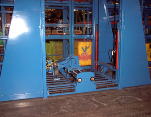
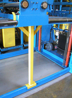
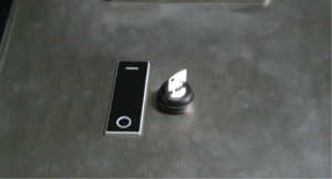
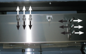



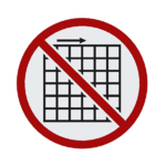








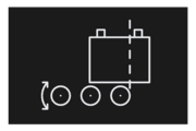

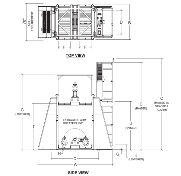
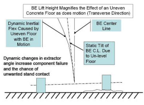
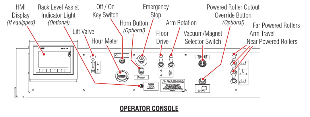
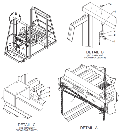
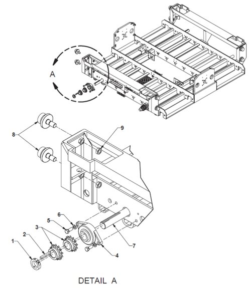
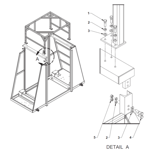
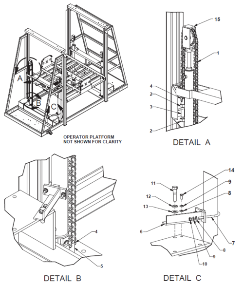
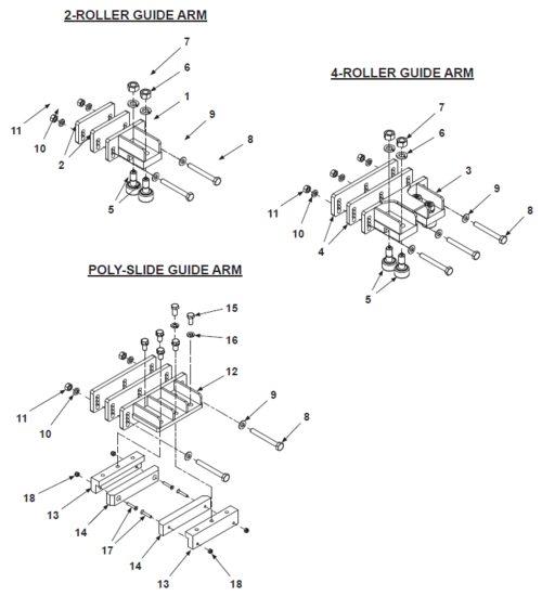
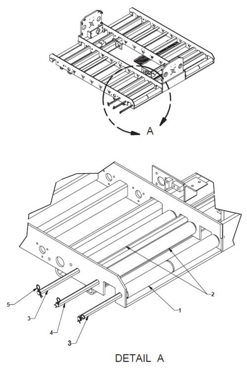
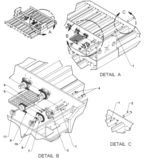
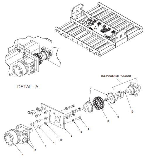
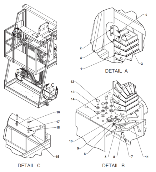
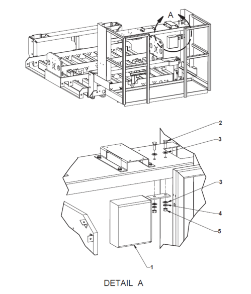
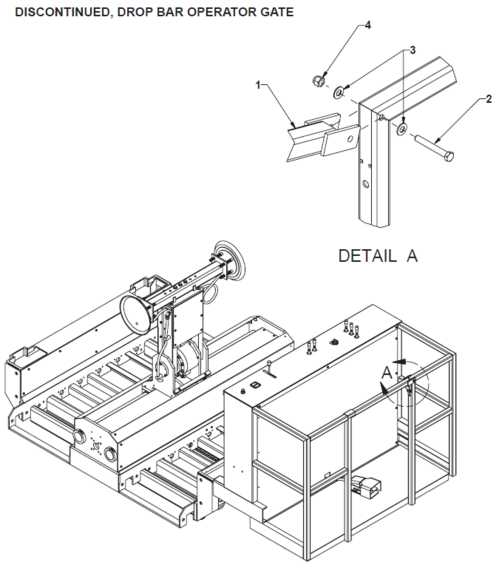
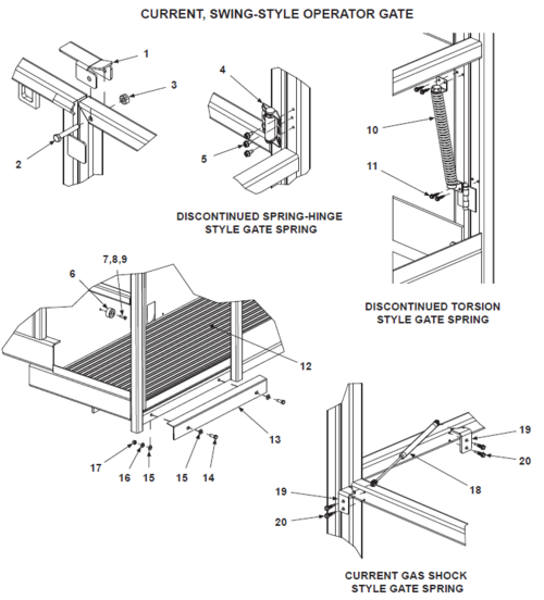
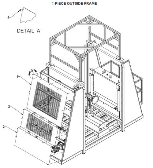
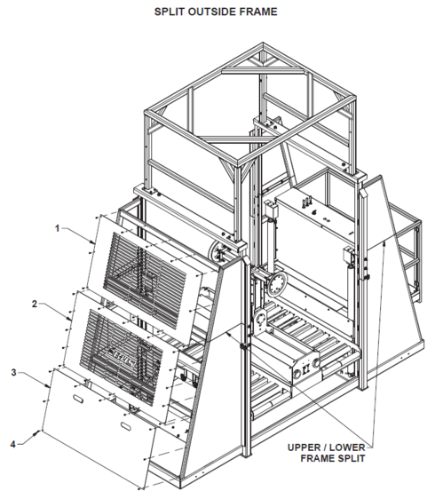
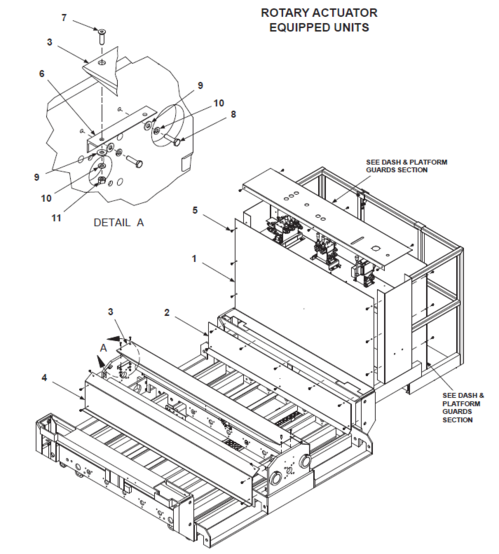
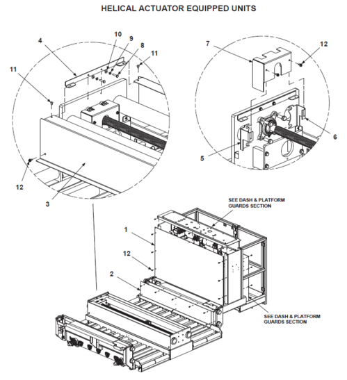
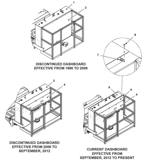
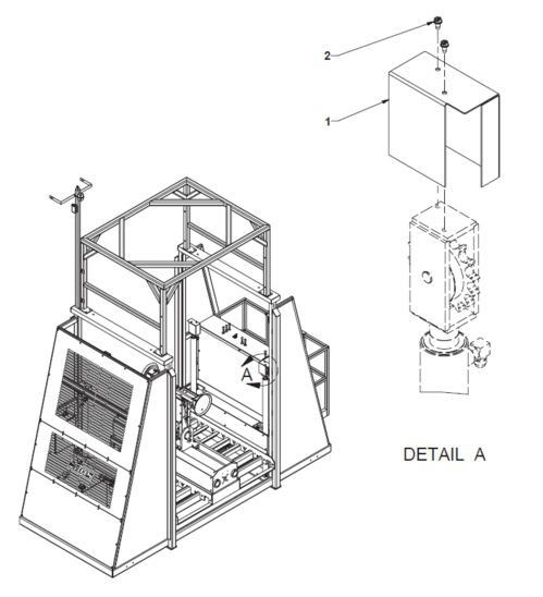
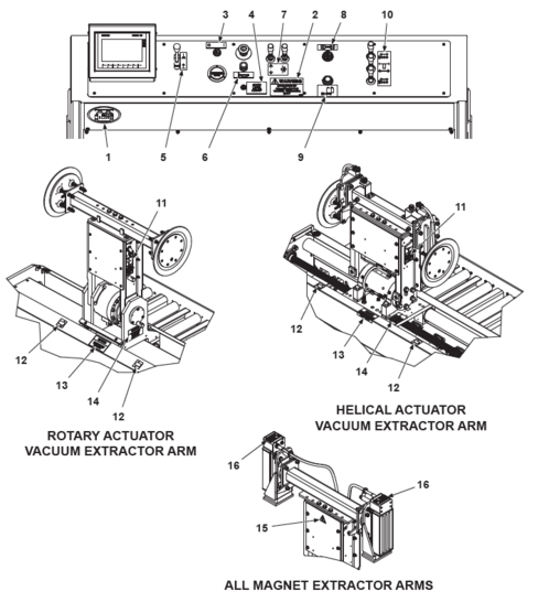
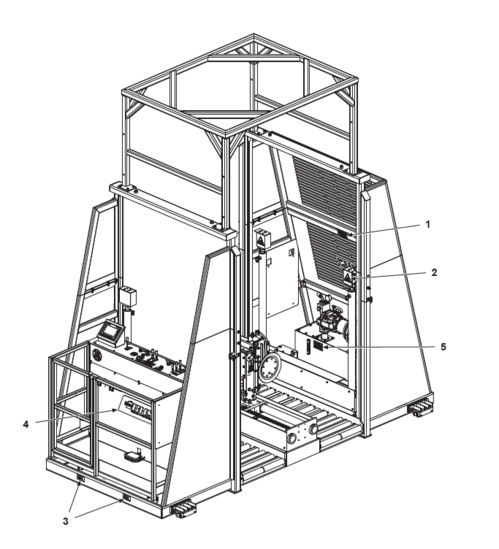
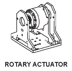
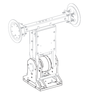
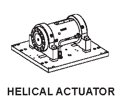
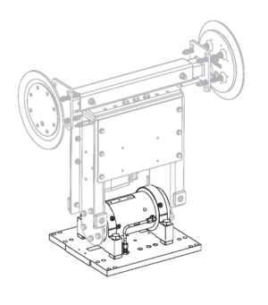
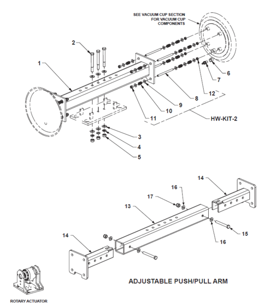
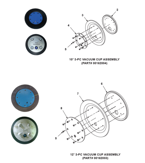
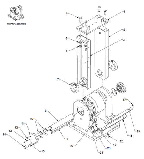
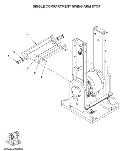
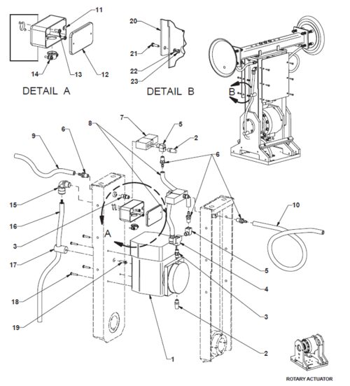
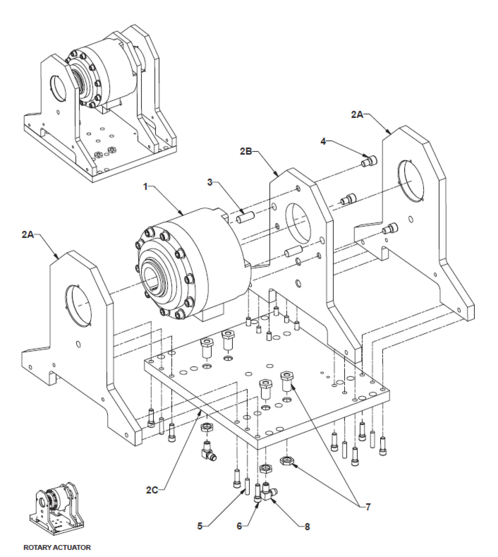
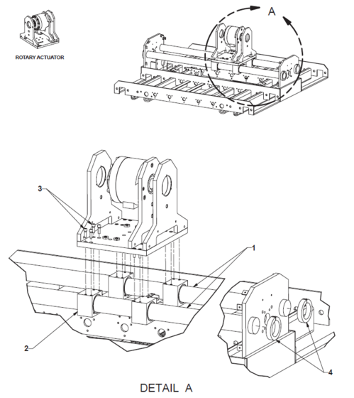
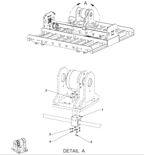
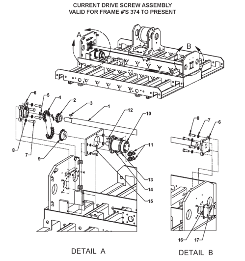
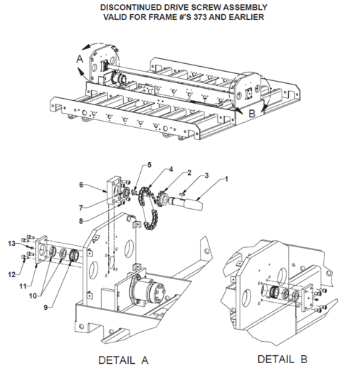
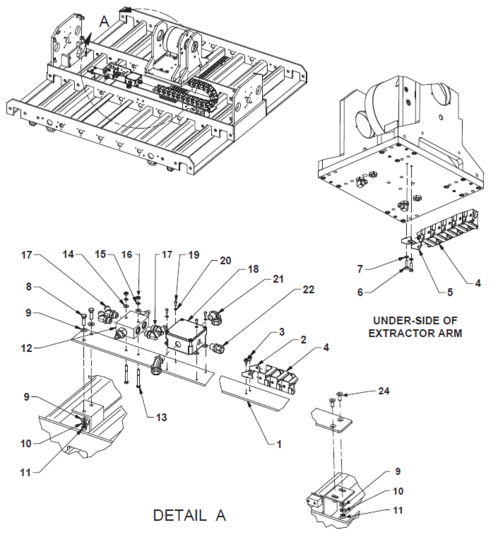
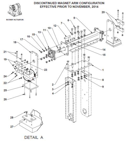
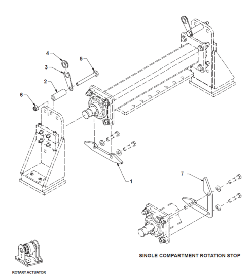
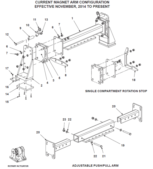
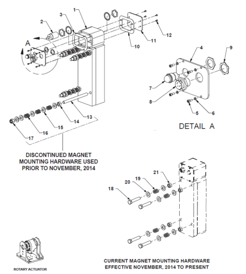
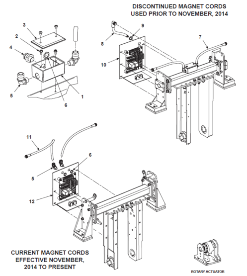
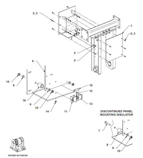
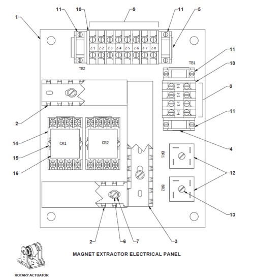
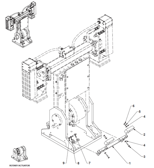
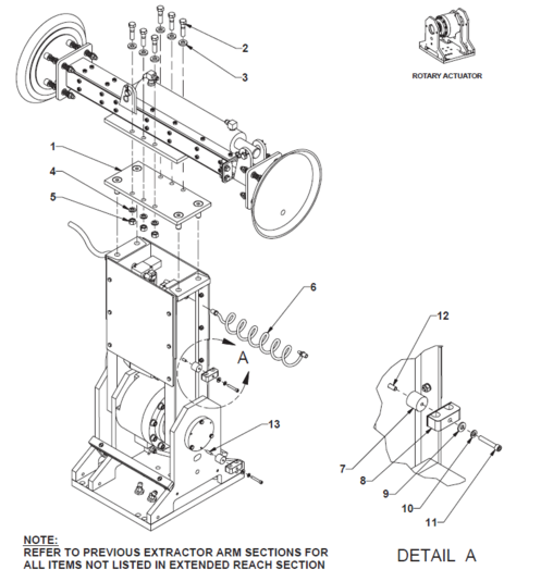
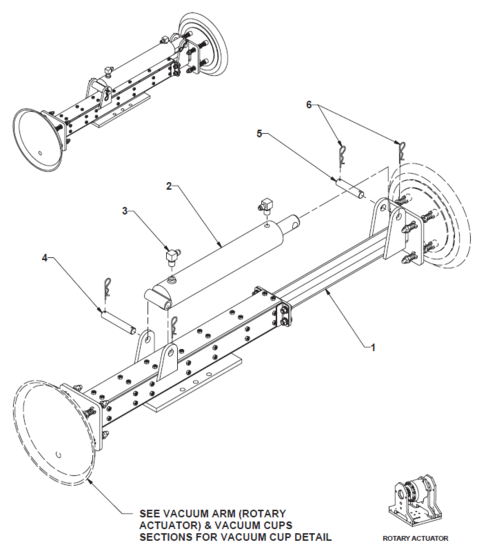
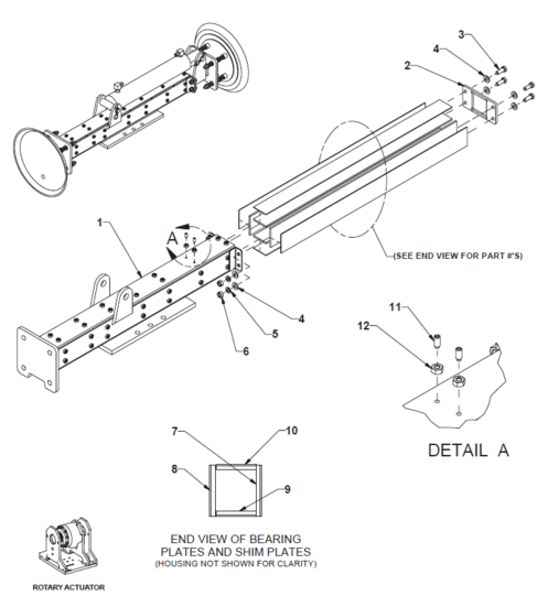
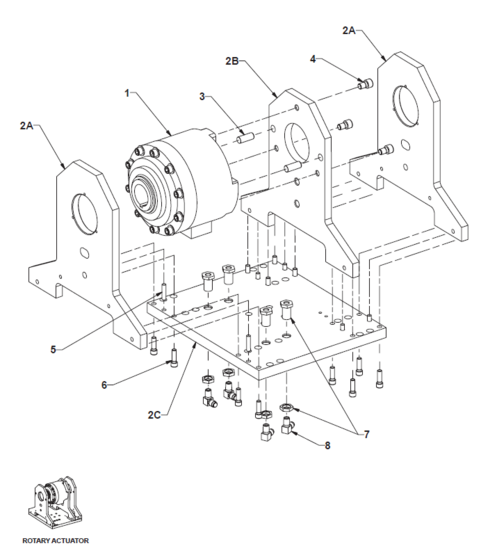
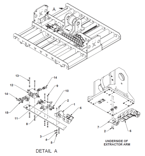
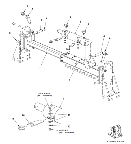
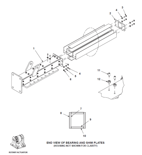
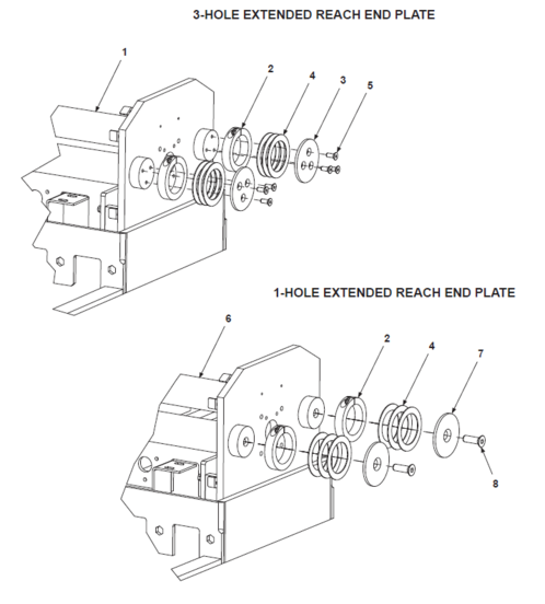
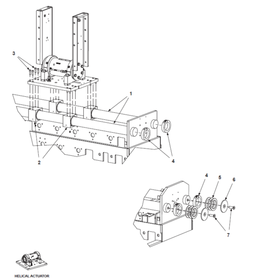
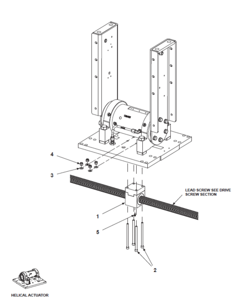
![BE-TS [Discontinued] Swing Arms & Actuator (Helical Actuator)](/images/thumb/f/f7/BE-TS_Swing_Arms_%26_Actuator_%28Helical_Actuator%29.png/498px-BE-TS_Swing_Arms_%26_Actuator_%28Helical_Actuator%29.png)
