Uncategorized files
Jump to navigation
Jump to search
Showing below up to 50 results in range #1,151 to #1,200.
View (previous 50 | next 50) (20 | 50 | 100 | 250 | 500)
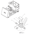 IOP-400 BE-SL&DS (10-23) Junction Box Diagram.png 701 × 788; 113 KB
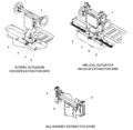 IOP-400 BE-SL&DS (10-23) Labels and Placards Parts.png 1,700 × 1,660; 80 KB
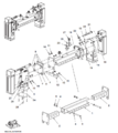 IOP-400 BE-SL&DS (10-23) Magnet Arm (Helical Actuator).png 698 × 783; 134 KB
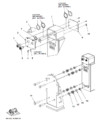 IOP-400 BE-SL&DS (10-23) Magnet Assembly (Helical Actuator).png 710 × 790; 104 KB
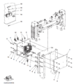 IOP-400 BE-SL&DS (10-23) Magnet Components (Helical Actuator).png 716 × 789; 134 KB
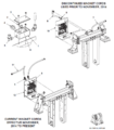 IOP-400 BE-SL&DS (10-23) Magnet Cords (Rotary Actuator).png 694 × 790; 134 KB
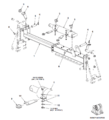 IOP-400 BE-SL&DS (10-23) Magnet Extended Reach (Rotary Actuator).png 712 × 786; 97 KB
 IOP-400 BE-SL&DS (10-23) Magnet Extraction.png 552 × 300; 17 KB
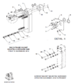 IOP-400 BE-SL&DS (10-23) Magnet Mounting Hardware (Rotary Actuator).png 690 × 789; 110 KB
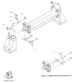 IOP-400 BE-SL&DS (10-23) Magnet Pivot Stop (Rotary Actuator).png 718 × 794; 98 KB
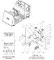 IOP-400 BE-SL&DS (10-23) Magnet Starter.png 704 × 793; 133 KB
 IOP-400 BE-SL&DS (10-23) No Riders Allowed.png 600 × 600; 90 KB
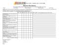 IOP-400 BE-SL&DS (10-23) Operator's Daily Checklist.png 1,236 × 953; 173 KB
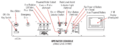 IOP-400 BE-SL&DS (10-23) Operator Console.png 1,417 × 545; 109 KB
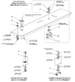 IOP-400 BE-SL&DS (10-23) Operator Console Parts.png 718 × 793; 106 KB
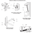 IOP-400 BE-SL&DS (10-23) Operator Gates.png 1,700 × 1,666; 61 KB
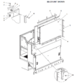 IOP-400 BE-SL&DS (10-23) Operator Shield.png 700 × 785; 95 KB
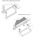 IOP-400 BE-SL&DS (10-23) Operator Step Styles.png 1,700 × 1,786; 56 KB
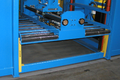 IOP-400 BE-SL&DS (10-23) Page 369 Image 0001.png 1,498 × 1,004; 1.84 MB
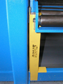 IOP-400 BE-SL&DS (10-23) Page 370 Image 0002.png 572 × 759; 740 KB
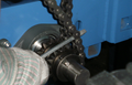 IOP-400 BE-SL&DS (10-23) Page 371 Image 0002.png 946 × 609; 729 KB
 IOP-400 BE-SL&DS (10-23) Page 374 Image 0005.png 493 × 267; 141 KB
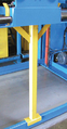 IOP-400 BE-SL&DS (10-23) Page 374 Image 0006.png 234 × 450; 176 KB
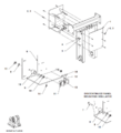 IOP-400 BE-SL&DS (10-23) Panel Mounting (Rotary Actuator).png 712 × 787; 83 KB
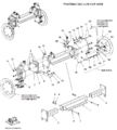 IOP-400 BE-SL&DS (10-23) Pivoting Vacuum Cup Arm (Helical Actuator).png 712 × 792; 157 KB
 IOP-400 BE-SL&DS (10-23) Power Rollers and Arm Travel.png.png 600 × 1,591; 22 KB
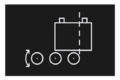 IOP-400 BE-SL&DS (10-23) Powered Roller Cut Off Override.png 559 × 372; 20 KB
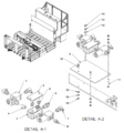 IOP-400 BE-SL&DS (10-23) Powered Roller Cutout Details.png 733 × 788; 136 KB
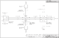 IOP-400 BE-SL&DS (10-23) Powered Roller Cutout Electrical Schematic.png 1,406 × 908; 93 KB
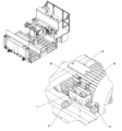 IOP-400 BE-SL&DS (10-23) Powered Roller Cutout Junction Box.png 700 × 750; 130 KB
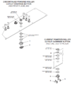 IOP-400 BE-SL&DS (10-23) Powered Roller Cutout Override Button.png 671 × 790; 85 KB
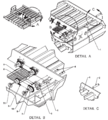 IOP-400 BE-SL&DS (10-23) Powered Rollers 1.png 1,640 × 1,816; 122 KB
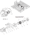 IOP-400 BE-SL&DS (10-23) Powered Rollers 2.png 696 × 786; 138 KB
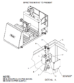 IOP-400 BE-SL&DS (10-23) Primary Fusing.png 706 × 789; 122 KB
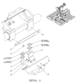 IOP-400 BE-SL&DS (10-23) Proximity Switch.png 714 × 773; 101 KB
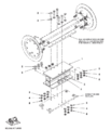 IOP-400 BE-SL&DS (10-23) Push Pull Arm Mounting (Helical Actuator).png 678 × 793; 114 KB
 IOP-400 BE-SL&DS (10-23) Rack-Level-Assist.png 559 × 372; 32 KB
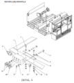 IOP-400 BE-SL&DS (10-23) Return Line Manifold.png 712 × 791; 135 KB
_Junction_Box_Diagram.png)
_Labels_and_Placards_Parts.png)
_Lift_%2B_Floor_Drive_%2B_Arm_Rotation_Valve_%26_Manifold_Detail.png)
_Magnet_Arm_(Helical_Actuator).png)
_Magnet_Assembly_(Helical_Actuator).png)
_Magnet_Components_(Helical_Actuator).png)
_Magnet_Cords_(Rotary_Actuator).png)
_Magnet_Electrical_Panel_(Helical_Actuator).png)
_Magnet_Extended_Reach_(Rotary_Actuator).png)
_Magnet_Extended_Reach_Bearing_and_Shim_(Rotary_Actuator).png)
_Magnet_Extended_Reach_End_Plates_(Rotary_Actuator).png)
_Magnet_Extraction.png)
_Magnet_Extraction_Prior_to_Nov_2014_(Rotary_Actuator).png)
_Magnet_Mount_Stop_Swing_Arm_(Rotary_Actuator).png)
_Magnet_Mounting_Hardware_(Rotary_Actuator).png)
_Magnet_Pivot_Stop_(Rotary_Actuator).png)
_Magnet_Starter.png)
_No_Riders_Allowed.png)
_Non-Pivoting_Vaccum_Cup_Arm_(Helical_Actuator).png)
_Operator%27s_Daily_Checklist.png)
_Operator_Console.png)
_Operator_Console_Parts.png)
_Operator_Gates.png)
_Operator_Shield.png)
_Operator_Step_Styles.png)
_Page_369_Image_0001.png)
_Page_370_Image_0002.png)
_Page_371_Image_0002.png)
_Page_374_Image_0005.png)
_Page_374_Image_0006.png)
_Panel_Mounting_(Rotary_Actuator).png)
_Pivoting_Cup_Extended_Reach_Vaccum_Arm_(Helical_Actuator).png)
_Pivoting_Vacuum_Cup_Arm_(Helical_Actuator).png)
_Power_Rollers_and_Arm_Travel.png.png)
_Powered_Roller_Cut_Off_Override.png)
_Powered_Roller_Cutout_Details.png)
_Powered_Roller_Cutout_Electrical_Schematic.png)
_Powered_Roller_Cutout_Junction_Box.png)
_Powered_Roller_Cutout_Override_Button.png)
_Powered_Roller_Cutout_Photo_Eye_%26_Reflector_Locations_(August_2022_to_Present).png)
_Powered_Roller_Cutout_Photo_Eye_Locations_(Prior_to_August_2022).png)
_Powered_Roller_Cutout_Reflector_Locations_(Prior_to_August_2022).png)
_Powered_Rollers_1.png)
_Powered_Rollers_2.png)
_Primary_Fusing.png)
_Proximity_Switch.png)
_Push_Pull_Arm_Mounting_(Helical_Actuator).png)
_Rack-Level-Assist.png)
_Return_Line_Manifold.png)
_Rollers_%2B_Arm_Traverse_Valve_%26_Manifold_Detaill.png)