Uncategorized files
Jump to navigation
Jump to search
Showing below up to 50 results in range #1,101 to #1,150.
View (previous 50 | next 50) (20 | 50 | 100 | 250 | 500)
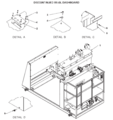 IOP-400 BE-SL&DS (10-23) Discontinued BE-SL Dashboard.png 1,700 × 1,798; 86 KB
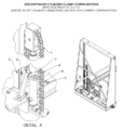 IOP-400 BE-SL&DS (10-23) Discontinued Cylinder Clamp Configuration.png 711 × 753; 136 KB
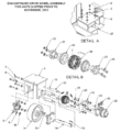 IOP-400 BE-SL&DS (10-23) Discontinued Drive Wheel Assembly.png 610 × 667; 123 KB
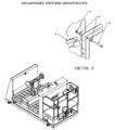 IOP-400 BE-SL&DS (10-23) Discontinued Drop Bar Barrier Gate.png 1,520 × 1,720; 66 KB
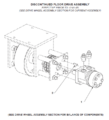 IOP-400 BE-SL&DS (10-23) Discontinued Floor Drive Assembly.png 643 × 708; 77 KB
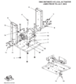 IOP-400 BE-SL&DS (10-23) Discontinued Helical Actuator.png 711 × 789; 95 KB
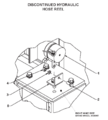 IOP-400 BE-SL&DS (10-23) Discontinued Hydraulic Hose Reel.png 1,130 × 1,259; 35 KB
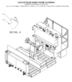 IOP-400 BE-SL&DS (10-23) Discontinued Inner Frame Guarding.png 677 × 764; 131 KB
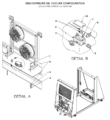 IOP-400 BE-SL&DS (10-23) Discontinued Oil Cooler Configuration.png 716 × 784; 166 KB
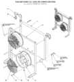 IOP-400 BE-SL&DS (10-23) Discontinued Oil Cooler Configuration 2.png 710 × 781; 169 KB
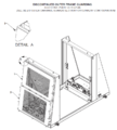 IOP-400 BE-SL&DS (10-23) Discontinued Outer Frame Guarding.png 702 × 782; 142 KB
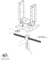 IOP-400 BE-SL&DS (10-23) Drive Nut Assembly (Helical Actuator).png 603 × 730; 70 KB
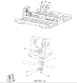 IOP-400 BE-SL&DS (10-23) Drive Nut Assembly Rotary Actuator.png 867 × 934; 113 KB
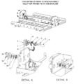 IOP-400 BE-SL&DS (10-23) Drive Screw (Rotary Actuator) Discontinued.png 730 × 779; 119 KB
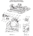 IOP-400 BE-SL&DS (10-23) Drive Screw Rotary Current.png 1,700 × 1,810; 88 KB
 IOP-400 BE-SL&DS (10-23) EQ Chain Attached to Upper Stud.png 555 × 214; 273 KB
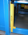 IOP-400 BE-SL&DS (10-23) EQ Chain Instructions-Figure1.png 607 × 759; 763 KB
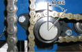 IOP-400 BE-SL&DS (10-23) EQ Shafts aligned 60 Degrees from Vertical.png 689 × 442; 684 KB
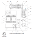 IOP-400 BE-SL&DS (10-23) Electrical Panel (Rotary Actuator).png 697 × 791; 85 KB
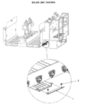 IOP-400 BE-SL&DS (10-23) Equalization Chain Hose Guard.png 609 × 770; 94 KB
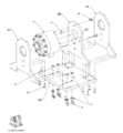 IOP-400 BE-SL&DS (10-23) Extended Reach (Rotary Actuator).png 729 × 789; 93 KB
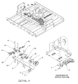 IOP-400 BE-SL&DS (10-23) Extended Reach 2 (Rotary Actuator).png 733 × 792; 136 KB
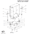 IOP-400 BE-SL&DS (10-23) Extended Reach Current Helical Actuator.png 685 × 792; 91 KB
 IOP-400 BE-SL&DS (10-23) Extractor Arm Positioning Arrows.png 420 × 203; 18 KB
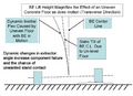 IOP-400 BE-SL&DS (10-23) Floor Conditions Pre-Installation Check.png 1,519 × 1,106; 279 KB
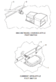 IOP-400 BE-SL&DS (10-23) Foot Switch.png 533 × 785; 64 KB
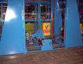 IOP-400 BE-SL&DS (10-23) Fully Lower BE Roller Bed.png 947 × 728; 1.14 MB
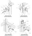 IOP-400 BE-SL&DS (10-23) Gate Switch.png 712 × 793; 106 KB
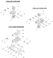 IOP-400 BE-SL&DS (10-23) Guide Arm.png 870 × 954; 110 KB
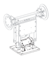 IOP-400 BE-SL&DS (10-23) Helical Actuator Extractor Arm.png 711 × 807; 20 KB
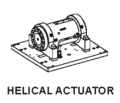 IOP-400 BE-SL&DS (10-23) Helical Actuator Symbol.png 250 × 215; 4 KB
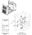 IOP-400 BE-SL&DS (10-23) High Performance Magnetic Starter Assembly.png 712 × 791; 155 KB
 IOP-400 BE-SL&DS (10-23) Horn Control.png 552 × 300; 11 KB
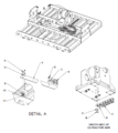 IOP-400 BE-SL&DS (10-23) Hose Carrier.png 701 × 783; 114 KB
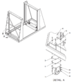 IOP-400 BE-SL&DS (10-23) Idler Casters.png 702 × 788; 97 KB
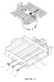 IOP-400 BE-SL&DS (10-23) Idler Rollers.png 523 × 785; 78 KB
 IOP-400 BE-SL&DS (10-23) Inside and Outside EQ Chains.png 1,377 × 442; 1.41 MB
_Discontinued_BE-SL_Counter_Balance_Valve_Configuration_(Prior_to_January_2004).png)
_Discontinued_BE-SL_Dashboard.png)
_Discontinued_BE-SL_and_BE-DS_with_Water_Cart_Wiring_Diagram.png)
_Discontinued_Cylinder_Clamp_Configuration.png)
_Discontinued_Drive_Wheel_Assembly.png)
_Discontinued_Drive_Wheel_Assembly_Used_Nov_2012_to_Nov_2013.png)
_Discontinued_Drop_Bar_Barrier_Gate.png)
_Discontinued_Extended_Reach_Magnet_Arm_(Helical_Actuator).png)
_Discontinued_Floor_Drive_Assembly.png)
_Discontinued_Helical_Actuator.png)
_Discontinued_High_Performance_Pressure_Releasing_Valve.png)
_Discontinued_High_Performance_Pump_and_Motor_Configuration.png)
_Discontinued_Hydraulic_Hose_Reel.png)
_Discontinued_Inner_Frame_Guarding.png)
_Discontinued_Lift_Circuit_Configuration_(Prior_to_July_2003).png)
_Discontinued_Lift_Cylinder_Configuration.png)
_Discontinued_Non_Pivoting_Cup_Extended_Reach_Vacuum_Arm_(Helical_Actuator).png)
_Discontinued_Oil_Cooler_Configuration.png)
_Discontinued_Oil_Cooler_Configuration_2.png)
_Discontinued_Outer_Frame_Guarding.png)
_Discontinued_Strobe_Light_%26_Stanchion_Configuration.png)
_Drive_Nut_Assembly_(Helical_Actuator).png)
_Drive_Nut_Assembly_Rotary_Actuator.png)
_Drive_Screw_(Rotary_Actuator)_Discontinued.png)
_Drive_Screw_Rotary_Current.png)
_EQ_Chain_Attached_to_Upper_Stud.png)
_EQ_Chain_Instructions-Figure1.png)
_EQ_Chain_Verify_equalization_sprocket_and_stud_alignment_by_using_a_6in_scale-Fig7.png)
_EQ_Chain_Verify_equalization_sprocket_and_stud_alignment_by_using_a_6in_scale-Fig8.png)
_EQ_Shafts_aligned_60_Degrees_from_Vertical.png)
_Electrical_Panel_(Rotary_Actuator).png)
_Equalization_Chain_Hose_Guard.png)
_Extended_Reach_(Rotary_Actuator).png)
_Extended_Reach_2_(Rotary_Actuator).png)
_Extended_Reach_Current_Helical_Actuator.png)
_Extended_Reach_Discontinued_Helical_Actuator.png)
_Extractor_Arm_Positioning_Arrows.png)
_Floor_Conditions_Pre-Installation_Check.png)
_Foot_Switch.png)
_Fully_Lower_BE_Roller_Bed.png)
_Gate_Switch.png)
_Guide_Arm.png)
_Helical_Actuator_Extractor_Arm.png)
_Helical_Actuator_Symbol.png)
_High_Performance_Magnetic_Starter_Assembly.png)
_Horn_Control.png)
_Hose_Carrier.png)
_Idler_Casters.png)
_Idler_Rollers.png)
_Inside_and_Outside_EQ_Chains.png)