IOP-080 Automatic Transfer Carriage (ATC)
Looking for a specific replacement part? Ctrl-F (or Command-F for Mac users) brings up your browsers search panel and can search any text on the entire web page. Find parts by searching a part # or part description.
Register your equipment with BHS Optima, BHS's free app.
California Residents: WARNING: This product contains chemicals known to the State of California to cause cancer and/or reproductive harm, and birth defects or other reproductive harm. Learn more here.

Automatic Transfer Carriage (ATC) Parts & Service Manual
The Automatic Transfer Carriage (ATC) is used to remove large batteries from electric industrial trucks. It is only used when attached to a host truck (fork truck / pallet truck). The host vehicle provides the ability for the ATC to raise and lower, as well as to travel across the floor.
The ATC is run by an operator that would typically be standing next to the ATC. The ATC is constructed of a steel frame, which houses the electrically powered hydraulic power unit. This provides the power for the arm to travel inward and outward. This function is controlled by a valve with a lever on the dash of the ATC. For vacuum cup equipped units, a vacuum pump is also contained within the frame. For magnet equipped units, the magnet is powered by the DC voltage of the host truck battery.
General Safety

|
|
- ATC units shall only be used indoors in an industrial setting on a hard, nonslip, and level floor without defects including but not limited to holes, gouges, cracks, drains or obstacles comprised of concrete or other suitable industrial material.
- Forces required to operate the ATC vary with weight of the load, floor conditions, and carriage conditions.
- ATC units are not designed to be shipped or transported after initial delivery.
- A licensed structural engineer should be consulted prior to installing an ATC on any building level other than the ground floor.
- Perform system and safety check before operating.
- Failure to follow these instructions and warnings may result in property damage, personal injury or death.
WORK AREA
- Keep work area clean and well lit. Cluttered work areas and poor lighting can lead to accidents.
- Clean up/contain any fluid spills immediately to prevent slips or falls.
- Be aware of potential hazards when performing any service or maintenance to the unit.
SERVICE & MAINTENANCE
Service personnel shall wear Personal Protective Equipment (PPE) appropriate for the task being performed.

|
LOCKOUT/TAGOUTLockout/tagout the SWT per your corporate policy, if damaged or not functioning properly. Lockout/tagout and de-energize all systems prior to performing any maintenance or service to unit. |

|
LEAD-ACID BATTERY EXPLOSION HAZARDDO NOT allow open flames or sparks of any kind near a battery. Highly explosive gas is generated when charging a battery that can remain in battery cells for extended periods of time after charging is complete.
|
|---|

|
HYDRAULIC HAZARDSAVOID HIGH PRESSURE FLUIDS - Escaping fluid under pressure can penetrate the skin causing serious injury. Relieve pressure before disconnecting hydraulic lines. Tighten all connections before applying pressure. Keep hands and body away from pin holes which eject fluids under high pressure. Use a piece of cardboard or paper to search for leaks. DO NOT use your hand. Any fluid injected into the skin under high pressure should be considered a serious medical emergency despite an initial normal appearance of the skin. There will be a delayed onset of pain, and serious tissue damage may occur. Medical attention should be sought immediately. |
|---|
Operational Safety
 
|
ELECTROMAGNET HAZARDUnits equipped with magnetic extraction generate strong magnetic fields. Persons with pacemakers SHOULD NOT operate or be in close proximity to equipment during operation. Failure to comply with this direction could result in serious personal injury or death. |
|---|
OPERATIONAL SAFETY
- Only personnel trained in the proper and safe operation of ATC units may operate or service the ATC.
- Operators shall wear appropriate PPE suitable for working with industrial lead-acid batteries while operating the ATC (see General Safety).
- All data plates, warning labels, placards, etc. shall be in place and legible at all times. Contact BHS for re-placement data plates, warning labels, placards or instructions.
- All users and service personnel shall be familiar with the meaning and risks associated with all data plates, warning labels, etc.
- All operators and service personnel shall be aware of potential crush and shear points while operating or servicing the ATC.
- ATC shall be operated in an area with ambient light levels of at least 50 lux.
- Keep hands and arms out of the battery compartment while operating the ATC.
- Engage the battery stop(s) and properly secure the battery prior to transporting the battery.
- Attach hook and chain (if equipped) to the battery prior to transporting the battery.
- Avoid abrupt changes in direction when transporting a battery in the ATC to prevent loss of the battery and/or loss of control of the pallet truck/ATC unit.
- Remove ATC from service if damaged, defective, or operating improperly (or becomes such while operating) until repairs can be made to correct any problem(s).
- ATC units must only be used to change batteries at the lowest level when used as a backup in a multi-level system to prevent loss of the battery and/or loss of control of the lift truck/ATC unit.
DO’s AND DON’T’s
- DO NOT exceed the maximum capacity of ATC.
- DO NOT perform ANY battery changes above the lowest level in a multi-level system.
- DO NOT modify or fit the ATC with attachments with-out prior, written approval from BHS.
- DO NOT perform any maintenance or service to the pallet truck or ATC with a battery loaded on the ATC.
- DO NOT allow anyone to ride in or on the ATC.
- DO NOT operate the ATC with any guard or cover re-moved unless required for maintenance or repair.
- Disconnect ATC from the host truck’s battery prior to charging the host truck battery.
- Disconnect ATC from all power sources before at-tempting to perform service or maintenance to the unit.
- Mount the ATC to a pallet truck with a capacity equal to or greater than the maximum capacity of the ATC.
- DO NOT lift the ATC while attached to the host truck.
- DO NOT use the ATC in a manner for which it is not intended. Some examples of prohibited use are but not limited t
- As a scooter or to transport people
- As a vehicle jack
- To lift loads greater than its rated load capacity
- Where unintentional movement may exist
- Having direct contact with foodstuffs
- In a potentially explosive atmosphere
De-Energization
ATC STANDARD
1. Disconnect the host truck's battery from its battery charger (if connected). If equipped with onboard battery and charger, unplug the charger.
2. Disconnect the DC power supply.
| Failure to Disconnect electrical power to the ATC could result in electrical shock. Serious personal injury or death will occur. |
|---|
a. If equipped with an onboard battery, remove the positive cable from the battery post. Secure the positive cable so it cannot contact the positive battery post. See Figure 1 .
-7-figure-1.jpg)
b. If connected to the host truck’s battery, unplug/disconnect the power connector/leads to the battery. See Figure 2.
-7-figure-2.jpg)
3. Cycle the manual valve several times to relieve stored hydraulic pressure. See Figure 3.
Failure to release any stored hydraulic pressure could result in injury from:
|
-7-figure-3.jpg)
ATC WITH REMOTE
1. Unplug the battery charger (if equipped).
2. Remove the green wire from the small, positive terminal of the solenoid. Secure the green solenoid wire so it cannot contact any other terminals, ground points or metal parts. See Figure 1.
-8-figure-1.jpg)
3. Activate the IN and OUT buttons of the remote to relieve stored hydraulic pressure. See Figure 2.
-8-figure-2.jpg)
4. Disconnect the DC power supply.
| Failure to Disconnect electrical power to the ATC could result in electrical shock. Serious personal injury or death will occur. |
a. If equipped with an onboard battery, remove the positive cable from the battery post. Secure the positive cable so it cannot contact the positive battery post. See Figure 3.
-8-figure-3.jpg)
b. If connected to the host truck’s battery, unplug/disconnect the power connector/leads to the battery. See Figure 4.
-8-figure-4.jpg)
Labels & Placards
Operators should be familiar with the meaning of the following labels and placards found on the ATC to ensure proper and safe operation.
|
|
Read and understand instruction manual prior to use. |
|---|---|

|
Consult manual for technical procedure. |

|
DO NOT operate with guards or covers removed. |
|
|
DO NOT operate by or in close proximity to people with pacemakers. |

|
Chain Entanglement Hazrd
|
|
|
Electrical Hazard
|
|
|
Strong Magnet Field Hazard
|

|
Extractor Arm Control In/Out |

|
Magnet On / Off (if Equipped) |

|
Vaccum On / Off (if Equipped) |

|
Power: Push & Hold |
Model Number & Options

NOMINAL ROLLER COMPARTMENT WIDTH
24 = 24" Wide Compartment
30 = 30" Wide Compartment
36 = 36" Wide Compartment
42 = 42" Wide Compartment
CANTILEVER / ROLLER BED EXTENSION *
CAN-7 = 7" Extension At Top, No Roller Bed Extension
CAN-7-6 = 7" Extension At Top, 6" Roller Bed Extension
CAN-14-6 = 14" Extension At Top, 6" Roller Bed Extension
CAN-14-8 = 14" Extension At Top, 8" Roller Bed Extension
* If no Cantilever option is listed (e.g. CAN-7) the unit is considered to be "standard" with no arm travel extension or roller bed extension.
EXTRACTION METHOD *
HC/VAC = Vacuum with Backup Hook & Chain
HC/MAG = Magnet with Backup Hook & Chain
* If no extraction method is listed (i.e. VAC or MAG) the extraction is Hook and Chain only.
MOUNTING METHOD
BLTON = Bolt on to Pallet Truck
FP = Fork Pockets for Lift Truck
FP-C = Fork Pockets for Pallet Truck
FP-3 = 3-way Fork Pockets for Pallet and Lift Truck
MPJ = Permanent Welding to Pallet Truck
ADDITIONAL OPTIONS *
ESC = Extra Service Capacity
HD = Heavy Duty Extraction Option
LPF = Low Profile Frame
LP = Low Profile Bolt in Slides
QDY = Electric Quick Disconnect “Y” Connector
MLI = Magnet Light Indicator (Magnet Units Only)
UNCTD = Uncoated Rollers (ATC-24 Units Only)
FS = Rear Friction Strips
RGD = Chain Guard Rubber Guards
BSELV = Base Elevation
DIR = Drop In Roller
DIR-LG = Drop In Roller for use with Bed Extension
DIR-FS = Drop In Roller with Rear Friction Strips
2TIER = Two Tier Roller Compartment (Upper and Lower Compartments)
BATT = Self-Contained Battery
CHGR = Self-Contained Charger (for use with ATC-BATT)
RMT = Remote Pendant Control
NS = Non-Standard / Custom Design or Components
* Consult factory for "NS" units to verify any custom components, if applicable
Models & Specifications
| ATC 24 | ATC 30 | ATC 36 | ATC 42 | |
|---|---|---|---|---|
| Max. Load Capacity 1 | 4,000 lbs / 1814 kg | 4,000 lbs / 1814 kg | 4,000 lbs / 1814 kg | 5,000 lbs / 2268 kg |
| Voltage Requirement | 12/24 V dc | 12/24 V dc | 12/24 V dc | 12/24 V dc |
| Hydraulic Pump | Gear | Gear | Gear | Gear |
| Extractor Arm Travel Speed | 0-24 ft/min
0.12 m/s |
0-24 ft/min
0.12 m/s |
0-24 ft/min
0.12 m/s |
0-24 ft/min
0.12 m/s |
| Battery Attachment | Hook & Chain Standard
Vacuum & Magnet Optional |
Hook & Chain Standard
Vacuum & Magnet Optional |
Hook & Chain Standard
Vacuum & Magnet Optional |
Hook & Chain Standard
Vacuum & Magnet Optional |
| Optional Magnet | 4” x 12” / 101 mm x 305 mm | 4” x 12” / 101 mm x 305 mm | 4” x 12” / 101 mm x 305 mm | 4” x 12” / 101 mm x 305 mm |
| Optional Vacuum 2 | 10” Diameter / 254 mm | 12” Diameter / 305 mm | 12” Diameter / 305 mm | 12” Diameter / 305 mm |
| Primary Drive Reduction | 2:1 | 2:1 | 2:1 | 2:1 |
| Primary Drive Chain Size | #50 | #50 | #50 | #50 |
| Roller Diameter | 2.4” / 61 mm | 2.4” / 61 mm | 2.4” / 61 mm | 2.4” / 61 mm |
| Roller Shaft Size | 7/16” Hex / 11 mm | 3/4” Hex / 19 mm | 3/4” Hex / 19 mm | 3/4” Hex / 19 mm |
| Battery Width | 6” Min. / 23” Max.
152 mm Min. / 584 mm Max. |
6” Min. / 29” Max.
152 mm Min. / 736 mm Max. |
6” Min. / 35” Max.
152 mm Min. / 889 mm Max. |
6” Min. / 41” Max.
152 mm Min. / 1041 mm Max. |
| Battery Length 3 | 41” Max. / 1041 mm | 41” Max. / 1041 mm | 41” Max. / 1041 mm | 41” Max. / 1041 mm |
| Min. Battery Height
Hook & Chain Magnet Vacuum |
12” / 305 mm
18” / 457 mm 21” / 533 mm |
12” / 305 mm
18” / 457 mm 21” / 533 mm |
12” / 305 mm
18” / 457 mm 21” / 533 mm |
12” / 305 mm
18” / 457 mm 21” / 533 mm |
| Overall Length | 62.75” / 1594 mm Standard
67.75”/ 1772 mm CAN-7 Option 76.75" / 1949 mm CAN-14 Option |
62.75” / 1594 mm Standard
67.75”/ 1772 mm CAN-7 Option 76.75" / 1949 mm CAN-14 Option |
62.75” / 1594 mm Standard
67.75”/ 1772 mm CAN-7 Option 76.75" / 1949 mm CAN-14 Option |
62.75” / 1594 mm Standard
67.75”/ 1772 mm CAN-7 Option 76.75" / 1949 mm CAN-14 Option |
| Overall Width | 29.5” / 749 mm | 35.5” / 902 mm | 41.5” / 1054 mm | 47.5” / 1207 mm |
| Overall Height | 34” / 864 mm | 34” / 864 mm | 34” / 864 mm | 34” / 864 mm |
| Base to Roller Height | 3” / 76 mm | 3” / 76 mm | 3” / 76 mm | 3” / 76 mm |
| Roller Width | 24.5” / 622 mm | 30.5” / 775 mm | 36.5” / 927 mm | 42.5” / 1079 mm |
| Extended Arm Reach (Beyond Roller Bed) | 6” / 152 mm Standard
13” / 330 mm Cantilever |
6” / 152 mm Standard
13” / 330 mm Cantilever |
6” / 152 mm Standard
13” / 330 mm Cantilever |
6” / 152 mm Standard
13” / 330 mm Cantilever |
| Rated Draw Bar Pull | 1,000 lbs / 453 kg | 1,000 lbs / 453 kg | 1,000 lbs / 453 kg | 1,000 lbs / 453 kg |
| Average Draw Bar Pull | 750 lbs / 340 kg Vacuum
775 lbs / 351 kg Magnet |
1,000 lbs / 450 kg Vacuum
775 lbs / 351 kg Magnet |
1,000 lbs / 450 kg Vacuum
775 lbs / 351 kg Magnet |
1,000 lbs / 450 kg Vacuum
775 lbs / 351 kg Magnet |
| Service Weight (unloaded)4 | 580 lbs / 263 kg | 640 lbs / 290 kg | 700 lbs / 317 kg | 770 lbs / 349 kg |
NOTES: BHS recommends that high-speed travel be disabled on pallet truck and maximum speed set at turtle or lowest setting.
1 Verify capacity of pallet truck being used at the specified load center (minimum 34” with 38” battery). Load center increases by 0.5” (12.7 mm) for every inch of battery over 38” (965 mm) in length. Certain options may affect load capacity. Consult factory.
2 Minimum battery width for 10” (254 mm) diameter vacuum is 11.5” (292 mm). Minimum battery width for 12” (305 mm) diameter vacuum is 13.75” (350 mm).
3 Consult factory for additional options.
4 Weight does not include options. Add 80 lb (36 kg) for magnet extraction.
Installation
The ATC can be mounted permanently by welding it to a pallet truck, semi-permanently by bolting it to a pallet truck using the bolt on option, or can be removable by way of fork pockets (FP-C and FP options.)
The following instructions will guide you through the installation of your ATC.
PERMANENT MOUNTING (WELDING) - STANDARD UNITS
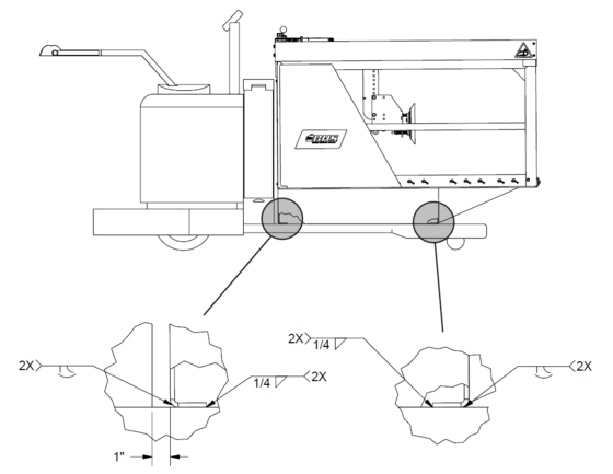
- Center the ATC on the forks of the pallet truck with the rear of the unit approximately 1" away from the pallet truck power head.
- Shim the unit to obtain 1/4"-1/2" rearward pitch. NOTE: Shim thickness will vary depending upon the amount of fork deflection and/or linkage wear of pallet truck load wheels. 1/4"-1/2" rearward pitch should be verified through the entire lift range of the pallet truck.
- Weld the unit to the forks as shown. NOTE: 27" x 48" or 27" x 60" forks are recommended. Some applications may require 27" x 60" forks only.
_ATC_Permanent_Mount_Welding_Standard.png)
PERMANENT MOUNTING (WELDING) - BSELV UNITS
- Center the ATC on the forks of the pallet truck with the rear of the unit approximately 1" away from the pallet truck power head.
- Verify rearward pitch. BSELV units are designed with 1/4" rearward pitch built into the frame structure. If unit does not have the required 1/4"-1/2" rearward pitch when placed on the pallet truck forks, shim the front of the unit to achieve the proper pitch. NOTE: Shim thickness will vary depending upon the amount of fork deflection and/or linkage wear of pallet truck load wheels. 1/4"-1/2" rearward pitch should be verified through the entire lift range of the pallet truck.
- Weld the unit to the forks as shown. NOTE: 27" x 48" or 27" x 60" forks are recommended. Some applications may require 27" x 60" forks only.
_ATC_Permanent_Mount_Welding_BSELV.png)
BOLT ON MOUNTING
- Center the ATC on the forks of the pallet truck with the rear of the unit against the pallet truck power head.
- Shim the unit to obtain 1/4"-1/2" rearward pitch. NOTE: Shim thickness will vary depending upon the amount of fork deflection and/or linkage wear of pallet truck load wheels. 1/4"-1/2" rearward pitch should be verified through the entire lift range of the pallet truck.
- Tack weld the shim to the unit to prevent it from moving.
- Locate the supplied mounting plates and hardware.
- Position mounting plate underneath one of the pallet truck forks aligned with the mounting holes in the rear rail of the ATC.
- Insert the 3/8-16 x 4" mounting bolts through the holes in the mounting plate and into the mounting holes of the unit. See Figure 1.
- Place one supplied flat washer and locking nut on each of the mounting bolts.
- Tighten the lock nuts evenly, ensuring the mounting plate is flat against the bottom of the fork when finished.
- Repeat Steps 5-8 for the opposite mounting plate.
_Page_014_Figure_1.jpg)
FP-C MOUNTING
- Lower the pallet truck forks to the fully lowered position.
- Slowly drive the pallet truck into the fork pockets, ensuring full engagement of the fork pocket "tongues" under the pallet truck power head. See Figure 2. NOTE: Minor modification of the fork pocket "tongues" may be required to attain full engagement with some pallet trucks.
_Page_014_Figure2.png)
| DO NOT use an ATC equipped with the FP-C option with a lift truck. A dangerous load shift can occur when handling a battery which can cause a possible loss of the battery and/or ATC and possible tip-over of the lift truck in which both situations can result in damage to the equipment as well as personal injury or even death. |
FP-MOUNTING
- Lower the lift truck forks to approximately 1/2"-3/4" off the floor.
- Position the forks to their widest point that will fit into the fork pockets.
Slowly drive the lift truck into the fork pockets until the forks are fully engaged in the fork pockets. See Figure 3.
)_FP-Mounting-Fig3.png)
ELECTRICAL CONNECTIONS
For ATC units equipped with the "QDY" option, unplug the pallet truck connector from the battery connector and plug the lift truck connector into one of the connectors on the ATC harness. Plug the unused connector on the ATC harness into the battery connector.
If the ATC unit was purchased without the "QDY" option, contact your local battery dealer for assistance in connecting the ATC cables to the pallet truck power cables.
NOTE: It is not recommended to hard wire the ATC cables directly to the battery terminals of the pallet truck battery. The ATC must be disconnected from the host truck’s battery before charging the battery.
HYDRUALIC SYSTEM
The reservoir should be filled within 1" of the top of the reservoir with approximately 0.8 Gal / 3.0 L of Chevron hydraulic oil AW ISO 32 or equivalent ISO 32 grade hydraulic oil with anti-wear additives and foam suppressant.
NOTE: It is not necessary to bleed the system after filling the unit.
_ATC_Hydraulic_Reservoir.png)
-7-figure-1.jpg)
-7-figure-2.jpg)
-7-figure-3.jpg)
-8-figure-1.jpg)
-8-figure-2.jpg)
-8-figure-3.jpg)
-8-figure-4.jpg)
_Page_014_Figure_1.jpg)
_Page_014_Figure2.png)
Operating Controls
_ATC_Operating_Controls.png)
| 1. Serial Number & Data Tag | Lists model number, serial number and specifications of unit. |
| 2. Vacuum / Magnet "On/Off' Switch | Turns Vacuum or Magnet (if equipped) on and off. |
| 3. Extractor Arm Control Handle | Controls extractor arm movement in and out of battery compartment. |
| 4. Power Push & Hold Button | Energizes main hydraulic power unit to move extractor arm in and out. |
| 5. "Ready" Status Indicator Light | Indicates the unit is in a "Ready to Use" status when lit (See "Service and Maintenance" section if light is not lit.) |
| 6. D.C. Input Power Cables | Main power cables to be connected to host pallet truck battery to supply power to unit. |