IOP-128 BT16-2
TP-621 - SAFETY AND DE-ENERGIZATION PROCEDURES
Register your equipment with BHS Optima, BHS's free app.
GENERAL SAFETY
- Read and understand all instructions and warnings before using or servicing this equipment.
- Keep these instructions for future reference.
- Bridge Trolley (BT) units shall only be used indoors in an industrial setting on a hard, nonslip, and level floor without defects including but not limited to holes, gouges, cracks, drains or obstacles comprised of concrete or other suitable industrial material.
- Forces required to operate the BT vary with weight of the load, floor conditions and carriage conditions.
- BT units are not designed to be shipped or transported after initial delivery.
- A licensed structural engineer should be consulted prior to installing a BT on any building level other than the ground floor.
- Perform system and safety check before operating.
- Failure to follow these instructions and warnings may result in property damage, personal injury or death.
WORK AREA
- Keep work area clean and well lit. Cluttered work areas and poor lighting can lead to accidents.
- Clean up/contain any fl uid spills immediately to prevent slips or falls.
- Be aware of potential hazards when performing any service or maintenance to the unit.
SERVICE & MAINTENANCE
Service personnel shall wear Personal Protective Equipment (PPE) appropriate for the task being performed.
LOCKOUT/TAGOUT
Lockout/tagout the BWC per your corporate policy, if damaged or not functioning properly. Lockout/tagout and deenergize all systems prior to performing any maintenance or service to unit.
LEAD-ACID BATTERIES-EXPLOSION HAZARD
![]()
Do not allow open flames or sparks of any kind near a battery. Highly explosive gas is generated when charging a battery that can remain in battery cells for extended periods of time after charging is complete.
- Always wear appropriate PPE including rubber apron, gloves, boots and full face shield when performing service or maintenance to any lead-acid batteries.
- Do not place metal or other conductive objects on top of battery. Arcing may occur causing damage to the battery and/or serious personal injury or death.
- Use only chargers matching the voltage and amperage of the battery being charged. Overcharging a battery can cause damage to the battery, charger and/or serious personal injury or death.
- Turn off charger before disconnecting battery from charger. Arcing between battery and charger connectors can cause damage to the connectors and/or serious personal injury or death.
HYDRAULIC HAZARDS
![]()
AVOID HIGH PRESSURE FLUIDS-Escaping fluid under pressure can penetrate the skin causing serious injury. Relieve pressure before disconnecting hydraulic lines. Tighten all connections before applying pressure. Keep hands and body away from pin holes which eject fluids under high pressure. Use a piece of cardboard or paper to search for leaks. DO NOT use your hand.
Any fluid injected into the skin under high pressure should be considered a serious medical emergency despite an initial normal appearance of the skin. There will be a delayed onset of pain, and serious tissue damage may occur. Medical attention should be sought immediately.
OPERATIONAL SAFETY
OPERATIONAL SAFETY
- Only personnel trained in the proper and safe operation of BT units may operate or service the BT.
- Operators shall wear appropriate PPE suitable for working with industrial lead-acid batteries while operating the BT (see prior page).
- All data plates, warning labels, placards, etc shall be in place and legible at all times. Contact BHS for replacement data plates, warning labels, placards or instructions.
- All users and service personnel shall be familiar with the meaning and risks associated with all data plates, warning labels, etc.
- All operators and service personnel shall be aware of potential crush and shear points while operating or servicing the BT, including the casters and brakes.
- BT should be operated in an area with ambient light levels of at least 50 lux.
- Keep hands and arms out of the battery compartments while operating the BT.
- Engage the battery stop(s) prior to transporting the battery.
- Remove BT from service if damaged, defective, or operating improperly (or becomes such while operating) until repairs can be made to correct any problem(s).
DO’s AND DON’T’s
- DO NOT exceed the maximum capacity of the BT.
- DO NOT modify or fit the BT with attachments without prior, written approval from BHS.
- DO NOT perform any maintenance or service to the BT with a battery loaded in the BT.
- DO NOT allow anyone to ride in or on the BT.
- DO NOT push the BT into the end stops.
- DO NOT operate the BT if off the designated travel path or guidance track.
- DO NOT use the BT in a manner for which it is not intended. Some examples of prohibited use are but not limited to:
           >>As a scooter or to transport people
           >>As a vehicle jack
           >>To lift loads greater than its rated load capacity
           >>Where unintentional movement may exist
           >>Having direct contact with foodstuffs
DE-ENERGIZATION
- Turn the pump release handle counterclockwise to lower the currently selected compartment and relieve any stored hydraulic pressure. See Figure 1
- Using the compartment selector valve, select the other compartment and repeat step 1. See Figure 2.
- Escaping hydraulic fl uid under high pressure (see HYDRAULIC HAZARDS in the GENERAL SAFETY section).
- Unexpected movement of hydraulic components.
_Page_07_figure1.jpg)
FIGURE 1
_Page_07_figure2.jpg)
FIGURE 2
![]()
Failure to lower the battery compartments when performing service to the BT could result in injury from the compartments lowering unexpectedly
Failure to release any stored hydraulic pressure could result in injury from:
LABELS & PLACARDS
TP-621(4).jpg)
GENERAL INFORMATION
The Bridge Trolley (BT) is used to remove large batteries from electric industrial trucks.
The bridge trolley is maneuvered manually along a designated travel path on casters by a person at the rear of the unit by pushing/ pulling on the handle of the unit. It is directed along this path by a guide track mounted permanently to the fl oor. The battery compartments are raised and lowered independently using a manual hand pump located at the rear of the unit with a manual valve to switch operation between compartments. The batteries are removed from the truck by the operator physically grasping the battery and pushing or pulling the batteries on and off of the unit.
_bt_16.JPG)
SPECIFICATIONS
A1.jpg)
INSTALLATION
The following describes the basic installation procedures for the bridge trolley system.
Once the trolley has been removed from the shipping pallet, some minor assembly may be required.
Note: If the unit has been shipped without the bridge attached, DO NOT remove the bands going across the unit in place of the bridge until the bridge has been fully installed.
Bridge Trolley
- Engage the floor locks to prevent the trolley from moving.
- Position the bridge as shown in Figure 1. Note: If unit is shipped with the bridge installed, steps 2 & 3 will be skipped.
- Install and tighten the bridge hardware. Carefully cut and remove banding.
- Determine which side of the trolley is to be the track side.
- Install the guidance arms on the track side of the unit as shown in Figures 2 & 3.
- Adjust the height of the guidance arms as necessary to ensure full engagement of the guide rollers with the entire length of track without the guidance arm bracket contacting the top edge of the track.
- Check the hydraulic pump oil level. Oil level should be 1" from the top of the reservoir. If low, fill with Chevron hydraulic oil AW ISO 32 or equivalent ISO 32 grade hydraulic oil with anti-wear additives and foam suppressant. Pump capacity is approximately 0.5 Gal (1.9 L). Note: Oil level must be checked with both roller compartments FULLY lowered. See Figure 4.
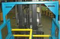
FIGURE 1
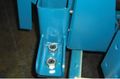
FIGURE 2

FIGURE 3
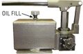
FIGURE 4
_Page_10_figure1.jpg)
_Page_10_figure2.jpg)
_Page_10_figure3.jpg)
_Page_10_figure4.jpg)
Guide Track
Note: Reference system layout drawing if available. If no drawing is available, proceed as follows.
- Single Change Out - Determine which end of the system will be the truck change out end. The opposite end will be the starting point for installing the track. 48" (1219 mm) over-travel will be required at this end to allow complete access of both battery compartments to the endmost battery stand compartment. Dual Change Out - If trucks are to be serviced at both ends of the system, it is recommended that the overall truck length, battery removal side and position all be verifi ed and then proper over-travel past the truck compartment be added to obtain track location (typically 48"/1219 mm).
- Measure and mark 2 7/8" (73 mm) from the front angle of the battery stands at each end of the system. See Figure 5.
- Using a chalk line, "snap" a line connecting the marks made in the previous step. This line will serve as an alignment guide for the location of the guide track. Note: Be sure to start the chalk line past the end of the stand allowing for over-travel of the trolley per step 1 and that the line is at least as long as the total length of track being installed.
- Position the fi rst piece of guide track ensuring it is aligned with the chalk line and the proper over-travel is accounted for. Place all track sections end to end to verify correct track length and location prior to anchoring.
- Install the guidance arms on the track side of the unit as shown in Figures 2 & 3.
- Adjust the height of the guidance arms as necessary to ensure full engagement of the guide rollers with the entire length of track without the guidance arm bracket contacting the top edge of the track.
- Check the hydraulic pump oil level. Oil level should be 1" from the top of the reservoir. If low, fill with Chevron hydraulic oil AW ISO 32 or equivalent ISO 32 grade hydraulic oil with anti-wear additives and foam suppressant. Pump capacity is approximately 0.5 Gal (1.9 L). Note: Oil level must be checked with both roller compartments FULLY lowered. See Figure 4.