Difference between revisions of "IOP-426 RNS-4-SS"
| Line 260: | Line 260: | ||
[[File:IOP-426-RNS-4-SS-(03-26-10)-12.jpg|500px|none|caption]] | [[File:IOP-426-RNS-4-SS-(03-26-10)-12.jpg|500px|none|caption]] | ||
FIGURE 2-1 | FIGURE 2-1 | ||
=== pH PROBE INSTALLATION AND TANK FILLING PROCEDURE === | |||
[[File:Notice sign.jpg]] | |||
The pH probe has been shipped in a wet state. It must remain wet, either in the solution which it was shipped, or its mounted position on the RNS with the cavity purged with water. If allowed to become dry, irreparable damage to the probe will occur. | |||
A.) Verify main water shut off valve in plumbing compartment is closed prior to | |||
filling tank. | |||
B.) Fill tank with a minimum of approximately 14” of water. | |||
C.) Locate pH probe in plumbing compartment and remove tie strap used in shipping. See Figure 2-2. | |||
D.) Slowly turn the main water shut off valve to the “ON” position. See Figure 2-3. Allow the air to purge from the water circuit until water just starts to come from the pH probe mounting port. See Figure 2-2. | |||
E.) Shut off water supply valve. Carefully remove the protective cap from the pH probe. Slide the probe into the port until it is fully seated and then screw the retaining nut down. HAND TIGHTEN ONLY! | |||
F.) Proceed to fill the tank no higher than the high water sensing switch located about 6” from the top of the left front corner. | |||
[[File:IOP-426-RNS-4-SS-(03-26-10)-13.jpg|500px|none|caption]] | |||
FIGURE 2-2 | |||
Revision as of 14:56, 3 August 2019
TP-602 - SAFETY AND DE-ENERGIZATION PROCEDURES
Register your equipment with BHS Optima, BHS's free app.
GENERAL SAFETY
- Read and understand all instructions and warnings before using or servicing this equipment.
- Keep these instructions for future reference.
- Follow all federal, state and local requirements for handling and treatment of battery wash cabinet effluent.
- Recirculation/Neutralization System (RNS) units are not designed to be shipped or transported after initial delivery.
- A licensed structural engineer should be consulted prior to installing a RNS on any building level other than the ground floor.
- Perform system and safety check before operating.
- Failure to follow these instructions and warnings may result in property damage, personal injury or death.
WORK AREA
- Keep work area clean and well lit. Cluttered work areas and poor lighting can lead to accidents.
- Clean up/contain any fluid spills immediately to prevent slips or falls.
- Be aware of potential hazards when performing any service or maintenance to the unit.
SERVICE & MAINTENANCE
Service personnel shall wear Personal Protective Equipment (PPE) appropriate for the task being performed.
LOCKOUT/TAGOUT
Lockout/tagout the BWC per your corporate policy, if damaged or not functioning properly. Lockout/tagout and deenergize all systems prior to performing any maintenance or service to unit.
LEAD-ACID BATTERIES-EXPLOSION HAZARD
.JPG)
Do not allow open flames or sparks of any kind near a battery. Highly explosive gas is generated when charging a battery that can remain in battery cells for extended periods of time after charging is complete.
- Always wear appropriate PPE including rubber apron, gloves, boots and full face shield when performing service or maintenance to any lead-acid batteries.
- Do not place metal or other conductive objects on top of battery. Arcing may occur causing damage to the battery and/or serious personal injury or death.
- Use only chargers matching the voltage and amperage of the battery being charged. Overcharging a battery can cause damage to the battery, charger and/or serious personal injury or death.
- Turn off charger before disconnecting battery from charger. Arcing between battery and charger connectors can cause damage to the connectors and/or serious personal injury or death.
BATTERY WASH WATER HAZARDS
HEAVY METALS:
Battery wash water contains heavy metals including (but not limited to) lead and antimony, which through prolonged exposure can lead to serious, long-term, adverse health conditions.
EXTREME pH LEVELS:
Highly acidic (low pH) as well as highly alkaline/ basic (high pH) solutions can cause severe burns, release toxic fumes, and cause violent chemical reactions when mixed with water or when mixed together.
- pH values outside of the BHS allowable range of 5 to 9 should be treated as “extreme” and caution should be taken to avoid direct contact with such solutions.
- Always wear appropriate PPE including rubber apron, gloves, boots and full face shield when working in contact with any battery wash water.
TREATMENT CHEMICALS:
Use of chemicals not approved by BHS to treat wash water may result in the release of toxic fumes.
OPERATIONAL SAFETY
OPERATIONAL SAFETY
- Only personnel trained in the proper and safe operation of RNS units may operate or service the RNS.
- Operators shall wear appropriate PPE suitable for working with industrial lead-acid batteries while operating the RNS (see prior page).
- All data plates, warning labels, placards, etc shall be in place and legible at all times. Contact BHS for replacement data plates, warning labels, placards or instructions.
- All users and service personnel shall be familiar with the meaning and risks associated with all data plates, warning labels, etc.
- Remove the RNS from service if damaged, defective, or operating improperly (or becomes such while operating) until repairs can be made to correct any problem(s).
- Only use BHS approved chemicals in the RNS. Severe chemical and/or toxic reactions may result.
DO’s AND DON’T’s
- DO NOT overfill the RNS reservoir.
- DO NOT operate the RNS when reservoir is empty.
- DO NOT modify or fit the RNS with attachments without prior, written approval from BHS.
- DO NOT operate the RNS with any guard or cover removed unless required for maintenance or repair.
- Disconnect RNS from all power sources before attempting to perform service or maintenance to the unit.
- DO NOT immerse any body part into the RNS holding tank water.
- DO NOT use any chemicals in the RNS that are not approved by BHS.
- DO NOT use the RNS to wash anything other than industrial lead-acid batteries.
- DO NOT use foaming type detergents in conjunction with the RNS.
- DO NOT use soda ash or similar types of neutralizers.
- Use only fully liquefi ed neutralizers.
- DO NOT spray personnel or electrical components with spray wand (if equipped).
- DO NOT use the RNS in a manner for which it is not intended. Some examples of prohibited use are but not limited to:
 » As an emergency wash station
 » As a parts washer
 » As a battery room wash-down device
 » As a battery acid disposal device
DE-ENERGIZATION
- Turn off and disconnect power to the RNS. (Note: The green power light will go out). See Figures 1.1 & 1.2.
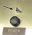
FIGURE 1.1
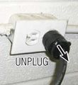
FIGURE 1.2
- Open the control panel door and remove the 17.5A fuse (the left most fuse) from the control board. See Figure 2.
- Reconnect power to and turn on the RNS.
- Press the RECIRCULATE button to activate the recirculation cycle (default time is 20 minutes). Turn off the RNS after 10 seconds. See Figure 3.
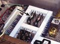
FIGURE 2
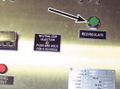
FIGURE 3
- If equipped with a spray wand, hold the trigger on the wand to release any residual pressure. If connected to a BWC, cycle the BWC through one complete wash to release residual water pressure. See Figures 4 & 5.
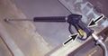
FIGURE 4
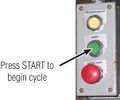
FIGURE 5
- Disconnect electrical power to the RNS.
TP-602_figure_1.1.jpg)
TP-602_figure_1.2.jpg)
TP-602_figure_2.jpg)
TP-602_figure_3.jpg)
.JPG) Failure to release any stored water pressure could result in an unexpected spray of wash water.
Failure to release any stored water pressure could result in an unexpected spray of wash water.
TP-602_figure_4.jpg)
TP-602_figure_5.jpg) Failure to disconnect electrical power to the RNS could result in electrical shock.
Failure to disconnect electrical power to the RNS could result in electrical shock.
INTRODUCTION
The RNS-4-SS is a closed loop system to supply and recycle the water used in cleaning forklift batteries.
The main objective of the RNS-4-SS is to::
1.) Remove contaminants associated with lead/acid batteries.
2.) Monitor the pH level of the water for neutralization as needed.
3.) Deter the growth of algae and bacteria via ozone purification.
The basic mechanical operation includes: pumping water from the reservoir through the filters, into a battery wash unit, through the sump assembly, and back into the reservoir.
The system consists of the following major components and assemblies.
A.) Completely self contained cabinet with integral 200 gallon tank.
B.) Electrical component area.
C.) pH meter with in-line probe.
D.) Water control solenoid valves
E.) Filters
F.) Water Pump
G.) Sump pump and float switch (remote mounted to wash cabinet)
H.) Ozone generator / neutralizer pump module
WATER MONITORING GENERAL DESCRIPTION
The pH level of the water stored in the RNS-4-SS is monitored by a panel mounted pH meter / controller which is supplied data from an in-line pH probe. In the event the water reaches preset parameters, the pH metering system is designed to shut off the system until the problem can be rectified. The only active circuit will be the recirculation mode.
WATER NEUTRALIZATION SYSTEM
The unit is designed with an onboard, manually operated neutralizer injection system that, when activated, injects approximately 6-8 ounces of solution into the tank. Actuating the recirculation circuit allows the neutralizer to be circulated and dispersed into the water.
OZONE GENERATOR GENERAL DESCRIPTION
The ozone generator supplies ozone to the water in the storage tank of the RNS-4-SS. Its function is to aid in the neutralizing process and inhibit the growth of bacteria and algae in the tank. It is designed to operate only when the pressure switch is activated, either during the recirculation or battery wash cabinet demand for flow.
PAGE_2.jpg)
LEADING PARTICULARS
PAGE_3.jpg)
FRONT & SIDE VIEW OF UNIT
PAGE_4.jpg)
INSTALLATION
GENERAL
The following paragraphs provide installation instructions for the RNS-4-SS. Instructions provided include: unpacking, positioning, power and water installation.
The following tools and materials will be required for system installation:
Channel Lock Pliers
Screw Driver (Standard, 1/4” Blade)
Adjustable Wrench (1/2”)
Measuring Tape (12’)
Level (12”)
Water Hose (length as required)
Liquid Neutralizing Conditioner (LNC) - one gallon supplied
Optional:
Heat Gun (to aid in hose attachment)
UNPACKING
A.) Place package system in general area of its operating location. Location considerations should be: within proximity to water supply, electrical power supply, vehicle entrance, and battery station locations.
B.) Cut wrapping bands and unstrap the system. Be careful not to scratch, cut or bend any components on system while unpacking.
C.) Inspect the system components for any signs of damage. Take particular note of any evidence of rough handling in transit. Immediately report any damage to shipping agent.
D.) Utilizing plant’s best technique, lift RNS-4-SS from its shipping skids and remove the skids from the area.
POSITIONING
The RNS-4-SS should be positioned where it will not interfere with the battery washing operation. Also, the distance from the battery wash unit should accommodate the interconnections between the system and the battery wash unit. The following paragraphs provide instructions for positioning of the system assemblies.
A.) Move RNS-4-SS into a position not further than 10 feet from the battery wash unit.
B.) Ensure that unit is level. If necessary, place shims under feet to level.
POWER CABLE
Unit is supplied with an AC line cord. A dedicated, 120 volt, 20 amp circuit with GFCI protection is required. The use of an extension cord is not recommended.
INNER CONNECTION TO WASH CABINET
There are 3 connections from the RNS-4-SS to a battery wash cabinet. (Typical BHS model number BWC-2).
A.) Attach the 3/4” I.D. hose from the water outlet of the RNS to the water inlet of the BWC-2. Note: This connection should be made AFTER completing procedures in Section 2-7.
B.) Attach the 1” I.D. hose from the sump pump outlet to the return inlet of the RNS.
C.) Connect the DC line cord from the sump pump to the 12 volt DC power outlet of the RNS.
SEE FIGURES 1-4 AND 2-1
-12.jpg)
FIGURE 2-1
pH PROBE INSTALLATION AND TANK FILLING PROCEDURE

The pH probe has been shipped in a wet state. It must remain wet, either in the solution which it was shipped, or its mounted position on the RNS with the cavity purged with water. If allowed to become dry, irreparable damage to the probe will occur.
A.) Verify main water shut off valve in plumbing compartment is closed prior to filling tank.
B.) Fill tank with a minimum of approximately 14” of water.
C.) Locate pH probe in plumbing compartment and remove tie strap used in shipping. See Figure 2-2.
D.) Slowly turn the main water shut off valve to the “ON” position. See Figure 2-3. Allow the air to purge from the water circuit until water just starts to come from the pH probe mounting port. See Figure 2-2.
E.) Shut off water supply valve. Carefully remove the protective cap from the pH probe. Slide the probe into the port until it is fully seated and then screw the retaining nut down. HAND TIGHTEN ONLY!
F.) Proceed to fill the tank no higher than the high water sensing switch located about 6” from the top of the left front corner.
-13.jpg)
FIGURE 2-2